Toward enhancing the autonomy of a telepresence mobile robot for remote home care assistance
←
→
Page content transcription
If your browser does not render page correctly, please read the page content below
Paladyn, Journal of Behavioral Robotics 2021; 12: 214–237
Research Article
Sébastien Laniel, Dominic Létourneau, François Grondin, Mathieu Labbé,
François Ferland, and François Michaud*
Toward enhancing the autonomy of
a telepresence mobile robot for remote home
care assistance
https://doi.org/10.1515/pjbr-2021-0016
received July 25, 2019; accepted March 2, 2021
1 Introduction
Abstract: In health care, a telepresence robot could be used Around the world, problems caused by population aging
to have a clinician or a caregiver assist seniors in their drive interest in developing new technology, including
homes, without having to travel to these locations. robotics [1,2], to provide home care. Telehomecare, or
However, the usability of these platforms for such applica- home telehealth, consists of providing health care ser-
tions requires that they can navigate and interact with a vices into a patient’s home [3] and is certainly an area
certain level of autonomy. For instance, robots should be of interest for telepresence mobile robots [4–9] in tasks
able to go to their charging station in case of low energy level such as telehomecare visits, vital sign monitoring and
or telecommunication failure. The remote operator could be Activity of Daily Living (ADL) assistance [9] for instance.
assisted by the robot’s capabilities to navigate safely at Mobile telepresence robotic platforms usually consist
home and to follow and track people with whom to interact.
of a mobile base, a camera, a screen, loudspeakers and
This requires the integration of autonomous decision-
a microphone, making them mobile videoconference
making capabilities on a platform equipped with appro-
systems, commonly referred by some to be “Skype on
priate sensing and action modalities, which are validated
wheels” [10]. Commercial consumer-based mobile tele-
out in the laboratory and in real homes. To document and
presence robotic platforms have been available over the
study these translational issues, this article presents such
last decade (see reviews in ref. [4,8,11–16]) and provide
integration on a Beam telepresence platform using three
mobility to sensors, effectors and interactive devices for
open-source libraries for integrated robot control architec-
ture, autonomous navigation and sound processing, devel- usage in hospitals, offices and homes [17], outlining
oped with real-time, limited processing and robustness recommendations for moving toward their use in prac-
requirements, so that they can work in real-life settings. tical settings. Most have no or very limited autonomy
Validation of the resulting platform, named SAM, is pre- [4,8,18] which, according to ref. [4], is attributed to sim-
sented based on the trials carried out in 10 homes. plicity, scalability and affordability reasons. For telehome-
Observations made provide guidance on what to improve care applications, the remote operator, who would most
and will help identify interaction scenarios for the upcoming likely be novice robot users (e.g., clinicians, caregivers),
usability studies with seniors, clinicians and caregivers. would find it beneficial to receive assistance in navigating
in the operating environment [4,16,19] and in following
Keywords: mobile robot assistant, assisted telepresence,
and tracking people (visually and from voice localization)
autonomous navigation, voice tracking, robot control archi-
with whom to interact [4,18]. Such capabilities would
tecture, evaluation in home settings
minimize what the remote operators have to do to control
the platform and to focus on the interaction tasks to be
* Corresponding author: François Michaud, Interdisciplinary conducted through telepresence [4,20].
Institute for Technological Innovation (3IT), Université de In addition, most of the work on telepresence are not
Sherbrooke, Sherbrooke, Québec, Canada, at all evaluated in real environments [21–24], nor do they
e-mail: francois.michaud@usherbrooke.ca
underline the difficulties encountered and the limitations
Sébastien Laniel, Dominic Létourneau, François Grondin,
Mathieu Labbé, François Ferland: Interdisciplinary Institute for
of their designs [1,2]. Autonomous capabilities can work
Technological Innovation (3IT), Université de Sherbrooke, well in lab conditions but may still have limitations when
Sherbrooke, Québec, Canada deployed in home environments, making it important to
Open Access. © 2021 Sébastien Laniel et al., published by De Gruyter. This work is licensed under the Creative Commons Attribution 4.0
International License.
Toward enhancing the autonomy of a telepresence mobile robot for remote home care assistance 215
conduct trials in such conditions to move toward the use interesting and detailed methodologies, observations and
of telepresence mobile robots for remote home care assis- requirements for moving forward with deploying telepre-
tance [4]. sence mobile robots for remote home care assistance. The
Addressing the issues of autonomy and trials in real Giraff robot platform is a closed system being available
home environments with a telepresence mobile robot only for purchase within Sweden at a cost of $11,900
requires to have access to such a platform along with USD.¹ It has a zoom camera with a wide-angle lens, one
the targeted autonomous capabilities. This article pre- microphone, one speaker, a 13.3″ LCD screen mounted on
sents how we try to address these design considerations top of a base and a charging station to charge its battery
by developing SAM [8], an augmented telepresence robot [29]. The Giraff robot is used to provide security, medical
from Suitable Technologies Inc. programmed using a follow-up and assistance to daily activities of seniors. It
robot control architecture with navigation and sound pro- has its own middleware for interfacing sensors [29,30].
cessing capabilities. To benefit from the progress made in Home sensors, medical sensors and the Giraff robot are
these areas and to be able to focus on the integration connected to a cloud-based system to retrieve the infor-
challenge in designing a robot for remote home care assis- mation taken by the various sensors to monitor the
tance, we use for convenience open-source libraries we patient’s activities, e.g., evaluates the daily time spent
designed and used by the research community. These sitting on a chair, detects in which room the elder is,
libraries are designed with online processing and real- monitors weight, blood pressure and blood glucose levels.
world constraints using robots with limited online proces- Short-term and long-term studies over 42 months and
sing capabilities in mind; and by being open-source, they 21 test sites in three European countries are reported
provide replicability of the implementation for experi- [4,25,28], along with insightful quantitative and qualita-
mental purposes. Results from trials conducted in 10 tive research methodologies of user needs and validation
home environments (apartments, houses and senior resi- [20,26,27] and design recommendations [4].
dences) are presented. Autonomous navigation capabili- One of such recommendation is as follows: “Developers
ties in reaching waypoints or going back to the charging of MRP system for use in homes of elderly people should strive
station are evaluated by navigating inside rooms or to to provide obstacle detection, and a map indicating the posi-
different rooms. Autonomous conversation following in tion of the robot, to ease the docking procedure” [4]. This is
quiet and noisy conditions is also evaluated. The purpose an essential feature to avoid having the remote operator
of these trials is to assess SAM in real home settings before teleoperate the robot back to its charging station at the
conducting usability studies, to determine the improve- end of a session, or to be moved out of the way by the
ments to be made and under which conditions its auton- occupant in case of low energy level or a telecommunica-
omous capabilities can be used. tion failure [4]. It requires the robot to have mapping and
The article is organized as follows. First, Section 2 localization capabilities, allowing it to navigate efficiently
presents related work on telepresence robots for home and safely in the home. High-level descriptions of autono-
care along with the design choices we made for the robot mous capabilities integrated for safe navigation (using a 2D
platform, the robot control architecture and the naviga- laser range finder and a camera) and user interfaces are
tion and sound processing capabilities. Sections 3 and 4 provided [4]. However, they are insufficient to reimplement
present SAM hardware and control implementation, them and their performance remain uncharacterized. To
respectively. Section 5 describes the experimental meth- build from the findings reported in the ExCITE project and
odology used to test SAM’s autonomous capabilities in provide additional contributions regarding autonomous
home settings, followed by Section 6 with results and capabilities requires having access to a telepresence devel-
observations. Section 7 presents the limitations of the opment platform. To provide a foundation on which to build
work reported, with Section 8 concludes the article. on, we decided to focus on three components related to
autonomy: robot control architecture, autonomous naviga-
tion and sound processing capabilities. Each autonomous
capability brings its share of individual and integration
2 Related work and design choices challenges [31] and is a research endeavour on its own.
Because providing detailed reviews of the state of the art
To our knowledge, the ExCITE (Enabling SoCial Inter- in each of these areas is outside the scope of the article,
action Through Embodiment) project [4,25–28] using the
Giraff telepresence robot is the only one that addresses
telepresence in the context of home care. It presents very 1 https://telepresencerobots.com/robots/giraff-telepresence
216 Sébastien Laniel et al.
the following subsections situate and explain the design principle of increasing precision with decreasing intelli-
choices we made to implement SAM and the targeted cap- gence [36]. The most common robot control architecture
abilities using our own libraries. used in this context has three layers: deliberative (high
level, abstract reasoning and task planning), executive
(task coordination) and functional (task execution). For
instance, the Donaxi robot [37,38] has a deliberative layer
2.1 Robot platform (for symbolic representation and reasoning), an executive
layer (for plan monitoring) and a functional layer. Siep-
For home care, telepresence robots should be lightweight mann et al. [39] uses a hardware layer, a functional layer
to facilitate their installation and their manipulation, and a BonSAI layer. The complexity in layered robot control
stable to avoid potential hazard in case of hardware architecture comes in how to interface and partition these
failure or physical contacts, and inexpensive. When we layers [40]. Although there is no consensus on a common
started this project in 2015, we first conducted a review architecture, how to engineer a system that effectively inte-
[8] of the different telepresence platforms to determine grates the functionalities required is an open question of
whether we needed to design our own or simply use one fundamental importance in robotics [41], and there is cur-
available in the market. Most platforms use differential rently no dominant solution [42].
drive locomotion with some being self-balanced using In our case, we use HBBA (Hybrid Behavior-Based
only two wheels, making them unstable if someone tries Architecture) [43,44], an open source² and unifying
to lean onto it. Omnidirectional locomotion facilitates framework for integrated design of autonomous robots.
navigation in tight spaces, which could be quite useful Illustrated Figure 1, HBBA is a behavior-based architec-
in homes if the cost of the platform remains low. UBBO ture with no central representation that provides the pos-
Maker robot [32] has such capability, but has limited pay- sibility of high-level modeling, reasoning and planning
load to add sensors for autonomous navigation or vital capabilities through Motivation or Perception modules.
sign monitoring. Based on these observations, we chose Basically, it allows Behaviors to be configured and acti-
to use the Beam platform. At the time, it was one of the vated according to what are referred to as the Intentions
least expensive platform (USD 2,000). It can be interfaced of the robot. Intentions are data structures providing
with the library presented in ref. [33] to control the the configuration and activation of Behaviors (i.e., the
motors with velocity commands and to read odometry. behavioral strategy) and the modulation of Perception
modules. As the number and complexity of Perception
modules, Behaviors and Motivations increase to address
more sophisticated interaction scenarios, the Intention
2.2 Robot control architecture Workspace becomes critical. While layered architectures
usually impose a specific deliberative structure (for
Providing more decisional autonomy to robots requires instance a task planner) to coordinate the lower-level
the use of a robot control architecture. Robot control Behaviors, HBBA can use multiple concurrent indepen-
architectures define the interrelations between decision- dent modules at its highest level, without constraining
making modules required by the application. With con- those modules to a specific decisional scheme. Compared
tinuous technological progress and availability of higher to more formal planning approaches such as Konidaris
processing and interacting capabilities, robot control inte- and Hayes [45], HBBA is a robot control architecture pre-
gration framework (a.k.a. architecture) facilitates expand- senting design guidelines and working principles for the
ability and portability. There is an infinite number of ways different processing modules, without imposing a formal
to implement robot control architectures (see review in ref. coding structure for its implementation. HBBA’s generic
[34]), making it hard to compare them [35] because research coordination mechanism of Behaviors has demonstrated
on robot control architectures is conducted more as feasi- its ability to address a wide range of cognitive capabili-
bility-type studies. For instance, designing robot control ties, ranging from assisted teleoperation to selective
architectures is being addressed in robot competitions attention and episodic memory, simply by coordinating
such as the RoboCup@HOME, aiming to develop service the activation and configuration of perception and beha-
and assistive robot technology with high relevance for vior modules. It has also been used with humanoid robots
future personal domestic applications. A frequently used
control architecture is the layered, or tiered, robot control
architecture, with layers usually organized according to the 2 http://github.com/francoisferland/hbba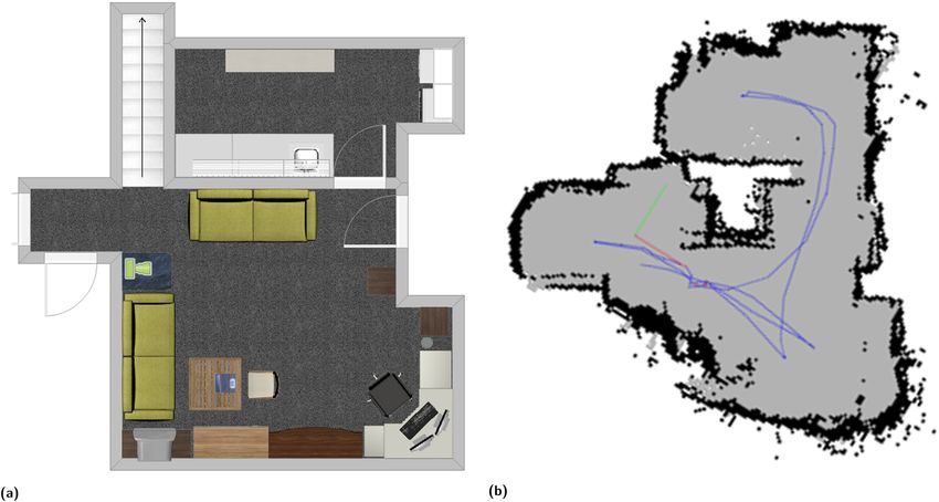
Toward enhancing the autonomy of a telepresence mobile robot for remote home care assistance 217
Message
with the current one. When loop closures are found
Motivation
Filter between the maps, a global graph can be created by com-
Percepts
Motivations bining the maps into one. However, for large-scale and
Organization
Layer long-term operation, the bigger the map is, the higher is
Beliefs and
Emotional
Signaling
Desires the computing power required to process the data online if
all the images gathered are examined. With limited com-
Coordination Intention puting resources on mobile robots, online map updating is
Layer Workspace limited, and so some parts of the map must be somewhat
forgotten.
Intentions and
Emotional Signaling Memory management approaches can be used to
Configuration
limit the size of the map, so that loop closure detection
Activation &
Perceptual
Behavior
Behavior Exploitation
Filtering
is always processed under a fixed time limit, thus satis-
fying online requirements for long-term and large-scale
environment mapping. RTAB-Map (Real-Time Appearance-
Based Mapping)³ [49–51] is an open-source library imple-
Behavioral Perception Behaviors
Layer menting such an approach, using images of the operating
Behavioral
Percepts environment. Being visual based, RTAB-Map can also pro-
vide 3D visualization of the operating environment from
Actions
video data, which may assist the remote user in navigation
Sensory
Inputs
tasks [4]. Released in 2013, RTAB-Map can be used as a
Action Selection cross-platform standalone C++ library and with its ROS
Commands package⁴ to do 2D or 3D SLAM.
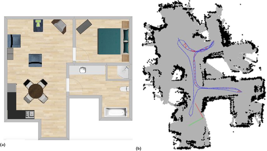
Sensors Actuators Figure 2 illustrates an example of a 3D and a 2D map
representations created with RTAB-Map using a Kinect
Figure 1: Hybrid behavior-based architecture (HBBA).
camera and a 2D LiDAR. These representations can be
useful to assist the remote operator, in particular the 3D
such as the NAO and Meka Robotics M1 in a episodic representation [4]. The Kinect camera generates a depth
memory sharing setup [46], and with the Robosoft Kompai image coupled with a standard RGB image, resulting in a
and later on the PAL Robotics TIAGo as service robots for colored 3D point cloud. The RGB image is also used to
the elderly with mild cognitive impairments [47]. calculate image features stored in a database. RTAB-Map
combines multiple point clouds together with transforms
(3D rotations and translations) from one point cloud to
the next. Estimation of the transforms are calculated from
2.3 Autonomous navigation the robot’s odometry using wheel encoders, visual odo-
metry or sensor fusion [52]. Image features from the cur-
SPLAM (Simultaneous Planning, Localization And Mapping) rent image are compared to the previously calculated
[48] is the ability to simultaneously map an environment, image features in the database. When the features have
localize itself in it and plan paths using this information. a strong correlation, a loop closure is detected. Accumu-
This task can be particularly complex when done online by lated errors in the map can then be minimized using the
a robot with limited computing resources. A key feature in new constraint leading to a corrected map [53]. As the
SPLAM is detecting previously visited areas to reduce map map increases in size, loop closure detection and graph
errors, a process known as loop closure detection. For optimization take more and more processing time. But
usage in home settings, the robot must be able to deal RTAB-Map’s memory management approach transfers,
with the so-called kidnapped robot problem and the initial when a fixed real-time limit is reached, i.e., oldest and
state problem: when it is turned on, a robot does not know less seen locations into a long-term memory where they
its relative position to a map previously created, and it has, are not used for loop closure detection and graph optimi-
on startup, to initialize a new map with its own referential; zation, thus bounding the map update time to a deter-
when a previously visited location is encountered, the
transformation between the two maps can be computed.
Appearance-based loop closure detection approaches exploit 3 http://introlab.github.io/rtabmap
the distinctiveness of images by comparing previous images 4 http://wiki.ros.org/rtabmap_ros
218 Sébastien Laniel et al.
Figure 2: Map generated by RTAB-Map. Figure 3: ODAS architecture.
mined threshold. When a loop closure is found with an sources. The module’s output can be used to continuously
old location still in working memory, its neighbor loca- orient the robot’s heading in the speaker’s direction, and
tions are brought back from the long-term memory to the sound locations can be displayed on the remote operator
working memory for additional loop closure detection 3D interface [56]. Sound sources are then filtered and
and to extend the current local map. separated using directive geometric source separation
(DGSS) to focus the robot’s attention only on speech,
and ignore ambient noise. The ODAS library also models
microphones as sensors with a directive polar pattern,
2.4 Sound processing which improves sound sources localization, tracking and
separation when the direct path between microphones
Robots for home assistance have to operate in noisy and the sound sources is obstructed by the robot’s body.
environments, and limitations are observed in such con- To make use of ODAS, a sound card and microphones
ditions when using only one or two microphones [54]. For are required. Commercial sound cards present limitations
instance, sound source localization could be used for when used for embedded robotic applications: they are
localizing the resident [4] or localizing the speaker when usually expensive; they have functionalities unnecessary
engaged in conversation with several users [18]. A micro- for robot sound processing and they also require signifi-
phone array can enhance performance by allowing a robot cant amount of power and size. To facilitate the use of
to localize, track and separate multiple sound sources to ODAS on various robotic platforms, we also provide as
improve situation awareness and user experience [18]. open hardware two sound cards [57]: 8SoundsUSB⁶ and
Sound processing capability, combined with face tracking 16SoundsUSB,⁷ for 8 and 16 microphone arrays, respec-
capabilities, can be used to facilitate localization of the tively. They provide synchronous acquisition of micro-
occupants [4] and to position the robot when conversing phone signals through USB to the robot’s computer.
with one or multiple people in the room [4,16,18,19], again
to facilitate the task of navigating the platform by allow-
ing the remote operator to focus on the interaction with
people. 3 SAM, a remote-assistance robot
ODAS [55] is an open-source library⁵ performing sound
sources localization, tracking and separation. Figure 3
platform
shows the main components of the ODAS framework.
A standard Beam platform comes with a 10″ LCD screen,
ODAS improves robustness to noise by increasing the
low-power embedded computer, two 640 × 480 HDR (High
number of microphones used while reducing computa-
Dynamic Range) wide-angle cameras facing bottom and
tional load. This library relies on a localization method
front, loudspeakers, four high-quality microphones, WiFi
called Steered Response Power with Phase Transform
network adapter, a 20-AH sealed lead-acid 12 V battery cap-
based on Hierarchical Search with Directivity model
able of approximately 2 hours of autonomy. It also comes
and Automatic calibration (SRP-PHAT-HSDA). Localiza-
with a charging station: the operator just has to position the
tion generates noisy potential sources, which are then
robot in front of it and activate the docking mode to let the
filtered with a tracking method based on a modified 3D
robot turn and back up on the charging station. The robot’s
Kalman filter (M3K) that generates one or many tracked
6 https://sourceforge.net/projects/eightsoundsusb/
5 http://odas.io 7 https://github.com/introlab/16SoundsUSB
Toward enhancing the autonomy of a telepresence mobile robot for remote home care assistance 219
dimensions are 134.4 cm (H ) × 31.3 cm (W ) × 41.7 cm (D). swapping for charging. Using an additional battery is
The platform also uses wheel encoders and an inertial mea- not ideal because it complexifies the charging process
surement unit to estimate the change in position of the of the robot, limiting its use to trained users. However,
robot over time. Motor control and power management this allows us to revert any changes and to keep our
are accomplished via an USB 2.0 controller in the robot’s modifications as less intrusive as possible. Coupled with
base, and its maximum speed is 0.45 m/s. DC–DC converters, the battery provides power to the
As shown by Figure 4, we placed a Kinect camera on microphone array, the Kinect and the NUC computer.
top of the LCD screen using custom-made aluminum The lithium-ion battery is recharged manually and sepa-
brackets, facing forward and slightly inclined to the rately. This configuration gives 50 minutes of autonomy
ground. Considering the Kinect’s limited field of view, when the robot maps its environment, and 75 minutes
placing the Kinect on top of the robot makes it possible when using navigation modalities (i.e., autonomous navi-
to prevent hitting hanging objects or elevated shelves and gation, teleoperation). Overall, the additional components
to perceive objects on tables or counters. We installed a plus the initial robot platform USD 4,300.
circular microphone array using a 8SoundsUSB [57] sound Telepresence robots used for health-care applica-
card and customized aluminum brackets and acrylic sup- tions, such as RP-VITA [59] and Giraff [60], interface
port plates at 67 cm from the ground. We added an Intel with vital sign monitoring devices for medical follow-
Skull Canyon NUC6i7KYK (NUC) computer equipped with up. To implement such capabilities, a low-cost USB dongle
a 512-GB hard drive, 32 GB RAM, a quad Core-i7 pro- is installed on SAM to acquire the following vital signs
cessor, USB3 ports, Ethernet and WiFi networking. We from battery-powered Bluetooth Low Energy (BLE) sen-
replaced the head computer’s hard drive with a 128-GB sors: blood pressure, SPO2 and heart rate, temperature,
mSATA drive. Both computers run Ubuntu 16.04 oper- weight scale and glucometer [61]. In our case, we also
ating system with ROS (Robot Operating Systems [58]) design our own telecommunication framework for tele-
Kinetic. We electrically separated the added components health applications [61], addressing the needs of remote
and the original robot by using SWX HyperCore 98Wh home care assistance applications.
V-Mount-certified lithium-ion battery (protected in over/
under-voltage and current) placed on the robot’s base
using a V-Mount battery plate, keeping the robot’s center
of gravity as low as possible and facilitating battery 4 SAM’s robot control architecture
Figure 5 illustrates the implementation of SAM’s robot
control architecture, following the HBBA framework, to
make SAM a remote home care assistance robot. As a
general overview, its main motivations are Survive and
Assistive Teleoperation. Survive supervises the battery
level and generates a Desire to go to the charging station
when the battery level is too low. Using the interface, the
remote operator can activate autonomous functionalities
managed by Assistive Teleoperation. This allows the user
to either manually control the robot, to communicate
a high level destination for autonomous navigation, to
autonomously track a face or autonomously orient SAM
toward a person talking. The following sections provide
more details on the Sensors, Perception, Behaviors, Actua-
tors and Motivations modules implemented for SAM.
4.1 Sensors
SAM has the following input sensory modules as shown
Figure 4: SAM with the added components to the Beam platform. in Figure 5.
220 Sébastien Laniel et al.
Figure 5: SAM’s robot control architecture using HBBA as the robot
control framework. Figure 7: Operator GUI.
• Battery-Level monitors the battery voltage level and • Head Camera is the webcam installed in SAM’s fore-
current consumption in floating point units. head, facing forward, for visual interaction with people.
• Gamepad is a wireless controller shown in Figure 6 and • Wireless Vital Sign Sensors is the BLE interface for the
used to activate or deactivate the wheel motors. It wireless vital signs monitoring devices.
allows the operator to manually navigate the robot or
to activate SAM’s autonomous modalities.
• Operator GUI (Graphical User Interface) shown in Figure 4.1.1 Perception
7 allows the operator to teleoperate SAM and to activate
the autonomous modalities using the icons on the The Perception modules process Sensors data into useful
bottom left portion of the interface. information for the Behaviors. SAM’s Perception modules
• Kinect is the RGB-D data generated by the Kinect shown in Figure 5 are:
camera. – RTAB-Map for mapping and localization, as presented
• Floor Camera is a webcam facing the ground and used in Section 2.3.
to locate the charging station. – Symbol Recognition uses Floor Camera to detect the
• Microphone Array is the 8-microphone array installed symbol on the charging station, shown in Figure 8,
on SAM. and identifies its orientation using ROS find_object_2d
• Odometry is data provided by wheel encoders and the package.⁸ This package uses OpenCV⁹ to detect the
inertial measurement unit of the Beam platform to esti- charging station. The homography between the corre-
mate its change in position over time. sponding features of the reference image and the scene
image is computed. Three points are chosen in the
reference image to estimate the pose of the object in
the scene image: one directly in the middle of the
object, one along the x axis of the object and one along
the y axis of the object. Knowing the angle of the Floor
Camera, the position (x , y ) relative to the robot is calcu-
lated.
– ODAS is for sound source localization, tracking and
separation, as explained in Section 2.4.
Figure 6: Gamepad used by the operator for teleoperation and for 8 http://wiki.ros.org/find_object_2d
testing SAM’s capabilities. 9 https://opencv.org/
Toward enhancing the autonomy of a telepresence mobile robot for remote home care assistance 221
Figure 8: SAM’s charging station.
Figure 9: 2D representation of the path generated by the Dock
behavior.
– Face Recognition uses SAM’s Head Camera in conjunc-
tion with FisherFaceRecognizer in openCV 3.0 library.
It compares the actual face with all the prerecorded (x1, y1). Symbol Recognition gives the position (xRS , yRS )
faces in its database. Then, Face Recognition identifies
and orientation θRS of the charging station relative to
the most likely person with a confidence score.
the robot. Then the robot position relative to the char-
– VSM (Vital Sign Monitoring) translates vital sign data
ging station (x1, y1) is found:
into a generic JSON format, to be compatible with soft-
ware used by Show and Log. x1 = −xRS cos θRS − yRS sin θRS (1)
y1 = xRS sin θRS − yRS cos θRS (2)
4.1.2 Behaviors To connect the robot perpendicularly to the charging
station, a second-order polynomial path is chosen:
SAM’s Behaviors, illustrated in Figure 5 and designed by y1 2
us, are control modalities organized with a priority-based y= x (3)
x1 2
action selection scheme as follows:
• Manual Teleoperation is the highest priority Behavior, Once the path is calculated, the initial orientation θi of
giving absolute control to an operator using the Gamepad. the robot is found using the derivative of (3). The robot
This Behavior is used for security interventions and dur- turns in place to reach θi . It then starts to move back-
ing a mapping session. wards following the path. To monitor the movement,
• Obstacle Avoidance plans a path around an obstacle Odometry provides the robot position (xMA , yMA ) and
detected in the robot’s the local map, to avoid collisions. orientation (θMA ) with respect to the map. This position
• Go To allows SAM to navigate autonomously using in relation to the charging station (xA, yA) is found
SPLAM provided by the RTAB-Map module. by applying the homogeneous matrices ( ARM , ASR ) that
• Dock allows the robot to connect itself to the charging change the coordinate system from map to robot and
station when it is detected. As shown in Figure 8, the from robot to charging station, respectively.
charging station has a flat part on which to roll over, xMA
xA
with a symbol used to calculate the distance and orien- yA = AR AS y A
M R
(4)
tation of the charging station. With the Beam head’s 1 M
1
hard drive replaced, we could not interface this beha-
vior with the existing docking algorithm of the Beam Using a cycling rate of 100 Hz, the velocities are defined
platform. Therefore, we had to implement our own. The by a translational velocity of 0.4 m/s and a rotational
robot charging connector is at the back of its base and velocity defined by:
there is no sensor to navigate backward. Therefore, θ°twist = θ A′ − θA × 100 (5)
before turning to dock backward, the robot must gen-
( )
erate a path. Shown in Figure 9, our algorithm uses a When Odometry indicates that the robot is not moving
(x , y ) representation centered on the charging station at and that there is indeed a non-zero speed command
(0, 0), pointing to the left (−x ) and the robot position at sent to the base, it means that the robot encountered
222 Sébastien Laniel et al.
an obstacle, potentially the charging station. It then
stops for 1 s; and if the battery’s current consumption
becomes negative within this period, the robot is docked
and charged. If not, the robot continues to back up
according to the calculated trajectory.
• Voice Following uses ODAS to perceive multiple sound
source locations, amplitudes and types (voice or non-
voice). The main interlocutor is considered to be the voice
source with the highest energy. Its location and the robot’s Figure 10: Face Following capabilities. (a) Face detected. (b) Covered
odometry are used to turn and face the main interlocutor. face. (c) Changed orientation.
• Face Following follows the closest face detected by Face
Recognition using the TLD Predator (Tracking Learning
and Detection) [62] package. As shown by Figure 10, once person’s face. By default, when no signals are coming
a face is detected, Face Following is able to the track it from Operator GUI, a Desire to return to the charging
even if it becomes covered or it changes orientation. The station is generated.
current implementation only tracks one face at a time.
• Speak converts predefined texts into speech using Festival
speech synthesis and the sound_play ROS package.¹⁰ 4.2 Validation in lab conditions
• Show displays, on the robot’s screen, the remote
operator webcam, vital signs and the robot’s battery SAM’s functionalities allows the operator to map the
level, as shown by Figure 7. environment, to navigate autonomously in the resulting
map and dock into its charging station, to let the robot
position itself in the direction of the person talking and to
4.1.3 Actuators track a person by following a face. These functionalities
can be individually activated using Operator GUI. Before
The Action Selection module receives all the Actions gen- conducting trials in real homes, we validated their effi-
erated by the activated Behaviors and keeps the ones from ciency and reliability in our lab facility. After having
the highest priority Behaviors for the same Actuator. created a reference map of hallways and rooms using
Actuators shown in Figure 5 are: RTAB-Map, autonomous navigation was tested by having
• Base translates velocity commands into control data for SAM move to different goal point locations. The robot
the wheel motors. safely moved in hallways, around people, around furni-
• Voice plays sounds coming from Speak or the audio ture (workbenches, tables, chairs, equipment of various
coming from the operator’s voice. types) and through door frames. To emulate home-like
• Screen displays the info from Show. conditions, the lab’s door frame was narrowed to 71 cm
• Log saves all vital signs gathered from VSM into a Firebase using a plywood. The charging station was placed
database, a Google web application.¹¹ Data are logged with against a wall in an open area to validate the motivation
a time stamp. Survive, i.e., making the robot return to the charging
station. This function was successfully validated over tra-
veling distance ranging from 1 to 20 m. Autonomous con-
4.1.4 Motivations versation following was tested in different rooms and
during public demonstrations. Face recognition was vali-
SAM’s Motivations are: dated with different participants individually, also in dif-
• Survive monitors SAM’s Battery Level and generates a ferent rooms. These trials done in controlled conditions
Desire to return to the charging station when battery were all successful, suggesting that SAM was ready to be
voltage is lower than 11.5 V. tested in more open and diverse experimental conditions.
• Assistive Teleoperation allows the remote operator,
using the GUI, to activate autonomous modes for navi-
gation, for following a conversation or for following a
5 Experimental methodology
10 http://wiki.ros.org/sound_play As stated in the introduction, the objective is to examine
11 https://firebase.google.com/ the efficiency and reliability of SAM’s modalities in real
Toward enhancing the autonomy of a telepresence mobile robot for remote home care assistance 223
home settings. In each new home setting, the first step
involved positioning the charging station against a wall
in an area with enough space (1 m2 ) for the robot to turn
and dock. Second, every door frame width, door threshold
height and hallway width were manually measured using
a tape measure, to characterize the environments and
provide observations when SAM experienced difficulties
in these areas. Environment limitations were also identi-
fied, specifically stairs, steps (≥0.5 cm) and rooms for-
bidden by the residents. Third, an operator created a refer-
ence map using the Gamepad and Manual Teleoperation
Figure 11: Kinect’s blind spot on SAM. Light gray area is interpreted
and by navigating in the different rooms, making sure to as safe zone for navigation, and dark gray as obstacle. The chair is
fully map the walls and furniture by looking at RTAB- seen here as a smaller obstacle because the blind spot covers part
Map’s reference map displayed using rviz. If the operator of it.
found the map to be an adequate representation of the
home, he then identified the locations for the Go To beha-
vior on the map. Since this article aimed to examine the
efficiency and reliability of SAM’s modalities in real home
settings, For consistency, the experiments were conducted
by the same person, experienced in operating SAM.
Early on, as we followed this process, we noticed that
some adjustments were required regarding SAM’s config-
uration and usage compared to its validation in labora-
tory conditions:
– The position of the Kinect camera brings limitations for
mapping and navigating. Illustrated in Figure 11, the
Kinect’s vertical field of view (FOV) of 60° creates a Figure 12: Misinterpretation error caused by vibrations on the Kinect
camera. Floor at 6 m of the Kinect is detected 20 cm higher if the
blind spot. The blind spot causes misinterpretations
pitch increases by 2°.
when approaching obstacles, like chairs and tables.
To limit this, the operator made the robot stay at least
40 cm away from obstacles that could be partially seen 5.1 Autonomous navigation
because of the blind spot. In addition, robot’s accele-
rations, floor slope and floor cracks generate vibrations. An autonomous navigation trial involves having SAM
And as shown in Figure 12, a change of 2° of the Kinect’s move from an initial to a goal location, which is referred
orientation can cause misinterpretation errors, for to as a path. For each trial, the operator used the Operator
instance, registering the floor as an obstacle. To prevent GUI to chose between the Go To behavior to go to a pre-
this, we set the minimum obstacle height at 20 cm. defined location or the Return to the charging station
– The Kinect camera has problems sensing mirrors or behavior to have SAM go to its charging station. As the
reflective objects: all obstacles reflected by a mirror robot moved during a trial, the operator held the enable
are seen as through a window. This adds noise or ghost button on the Gamepad and looked at RTAB-Map’s refer-
obstacles. We tried to minimize this effect by first map- ence map and the video feeds from both the Head Camera
ping rooms with large mirrors and then proceed with and the Floor Camera, releasing the enable button to
the other rooms, attempting to remove noise and ghost intervene when necessary. Since SAM is a telepresence
obstacles. robot, we consider such intervention acceptable to com-
– Difficulties were noticed with Face Following. With the pensate for the robot’s limitations. The operator then
change in brightness level between each room and used Manual Teleoperation behavior to reposition the
with time of day, Face Following revealed to be unreli- robot. For additional safety purposes, another person
able in real-life conditions while it performed well in was also physically following SAM, ready to intervene if
the lab. We therefore decided to leave this function- necessary. A trial is considered successful when the robot
ality out of the experiments, to focus on autonomous reaches its goal and the operator intervenes at most once
navigation and autonomous conversation following. to recover from the following types of cases:224 Sébastien Laniel et al.
• Avoid a collision by changing the robot’s orientation to the other rooms, attempting to remove noise and ghost
move away from the obstacle. obstacles.
• Overcome a path planning failure. Third, the robot’s odometry influences navigation
• Reposition the robot if the charging station is not performance. SAM’s Odometry is calculated by the Beam
visible from the Floor Camera or if the docking attempt base using wheel encoders and an inertial measurement
was unsuccessful. unit. Rotation error is around 2.8% and linear error is
roughly 0.8%. For each rotation in place, Odometry accu-
Depending on path taken from the initial and goal mulates an error of up to 10° , which decreases the quality
locations, trials were conducted, in no particular order, in of the map derived by RTAB-Map.
the following four navigation scenarios: Lastly, when mapping, RTAB-Map memorizes images
1. Navigate in a room: the robot receives a destination with their visual features as references for loop closure.
and creates a path between its initial and final posi- Loop closure occurs when a match is found between the
tions, without having to cross a hallway or a door current image and an image in memory, using similarity
frame. measures based on visual features in the images. One
2. Navigate to a different room: the robot has to move limitation is that every feature is assumed to be static
through door frames and hallways, making it possible and significant. This turned out to be problematic for
to assess the impact of door frame sizes and hallway autonomous navigation in laundry rooms and kitchens.
width during navigation. For example, the top room of Environment B in Figure 17a
3. Return to the charging station located in the same room: is a laundry room. The first time the room was mapped, it
this involves to autonomously navigate and dock into had colorful clothes folded on the ironing table. The next
the charging station located in the same room. day, RTAB-Map was unable to perform loop closure
4. Return to the charging station located in a different because the clothes were gone and the colorful features
room: same task but having the robot go through one were not visible. This problem can occur in all kinds of
or multiple door frames and hallways. context in the homes like mapping dishes, food, shoes,
clothes, pets, chairs, plants or even doors (opened or
For each trial, the robot’s path, the time elapsed and the closed). When RTAB-Map is unable to perform loop clo-
distance travelled were recorded. The type and number of sure, the odometry error accumulates and the local map
operator interventions were also noted, along with obser- drifts from the global map. If the drift becomes too large,
vations during door frame crossing. RTAB-Map is unable to find a possible path to both satisfy
the local map and the global map, making autonomous
During mapping, observations were made regarding navigation impossible. In this situation, the operator has
the creation of the reference map in real homes with SAM. to intervene and manually navigate the robot until RTAB-
First, the position of the Kinect camera brings limitations Map can perform a loop closure, resynchronizing SAM’s
for mapping and navigating. Illustrated in Figure 11, position in the map.
the Kinect’s vertical field of view (FOV) of 60° creates
a blind spot. The blind spot causes misinterpretations
when approaching obstacles, like chairs and tables. To
limit this, the operator made the robot stay at least 40 cm 5.2 Autonomous conversation following
away from obstacles that could be partially seen because
of the blind spot. In addition, robot’s accelerations, floor Autonomous conversation following aims to enhance
slope and floor cracks generate vibrations. And as shown the operator experience by autonomously directing the
in Figure 12, a change of 2° of the Kinect’s orientation can camera toward the person talking. Since face following
cause misinterpretation errors, for instance, registering isn’t reliable, we only test the Voice Following behavior.
the floor as an obstacle. To prevent this, we set the min- To provide repeatable experimental conditions, a pre-
imum obstacle height at 20 cm. recorded audio conversation between two men was played
Second, the Kinect camera has problems sensing from two speakers. Shown in Figure 13, the speakers were
mirrors or reflective objects: all obstacles reflected by placed at different heights (43 cm to 1.4 m), angles (120° to
a mirror are seen as through a window. This adds noise 150° ) and distances (1 m to 1.6 m) in environments A, B, E
or ghost obstacles. We tried to minimize this effect by first and J. The operator enabled the Voice Following behavior
mapping rooms with large mirrors and then proceed with using the Operator GUI and played the pre-recordedToward enhancing the autonomy of a telepresence mobile robot for remote home care assistance 225
each reference map, two to six paths were tested, with
each path repeated for at least three trials. Overall, 400
autonomous navigation trials were conducted.
As shown in Figure 14, trials lasted between 14 and
158 s, with an average of 38.5 s and a standard deviation
of 19.5 s. Trials done autonomously lasted between 14 and
87 s, with an average of 30 s and a standard deviation of
11.1 s. Trials involving interventions from the operator
lasted between 17 and 158 s, with an average of 53.7 s
and a standard deviation of 24 s. Distances travelled are
between 3.4 and 11.9 m, with an average of 6.9 m and
Figure 13: Speaker configurations for autonomous conversation
a standard deviation of 2.3 m.
following. Table 1 presents results of the trials in relation to the
four autonomous navigation scenarios defined in Section
5.1. Allowing the operator to intervene once (as explained
conversation, during which the active speaker changed 12 in Section 5.1) led to 80 additional successful trials (368)
times. The operator observed and noted whether the robot compared to trials completed autonomously (288). Only
was able to orient itself toward the active speaker when 32 trials (400 minus 368, about 8.0%) were unsuccessful.
more than four syllables were heard. When (1) Navigating in a room or (2) Navigating to a dif-
Tests were conducted in two conditions: ferent room, SAM succeeded in 264 trials (94 + 170) over
• Quiet: no loud interference was heard throughout the 270 trials (97 + 173) with intervention (i.e., 264 over 270
conversation. giving 97.8%), with 76.7% (81 + 126 = 207) autonomously.
• Noisy: having typical sounds occurring in the home. In these successful trials, the operator intervened 70 times
For instance, home residents were told to resume their (11 + 5 + 36 + 18) in 63 trials: 47 () to prevent collision and
normal activities and therefore could watch television, 23 (5 + 18) to recover from a path planning failure because
listen to music, prepare meals, vacuum, etc., in addition of loop closure problems. Also, (2) Navigating to a different
to having regular home noise (e.g., kitchen hood, fan). room revealed to be more difficult, with 72.8% success rate
for autonomous navigation compared to 83.5% of (1) Navi-
gating in a room. These difficulties can be explained by the
following:
6 Results and observations • The robot’s odometry influences navigation performance.
SAM’s Odometry is calculated by the Beam base using
Table 4 of Appendix A presents the 10 different home
wheel encoders and an inertial measurement unit. Rota-
settings where we conducted trials. They include a variety
of different types of rooms, floor types, door widths and
hallways, and configurations of various furniture. None
were modified or adjusted to help the robot, except for
doors that were either fully opened or closed. The sketches
provided in Appendix A are approximate representations
of the real homes. Examples of reference maps generated
by RTAB-Map are also provided. The dark lines in the
maps are obstacles and the gray areas are the safe zones
for navigation. Home availability for experimentation
ranged from 2 hours to 2 weeks.
6.1 Autonomous navigation
Depending on the availability and complexity of the home,
one to five reference maps were created for each of the 10
home environments, for a total of 35 reference maps. For Figure 14: Histogram of time taken for trials.226 Sébastien Laniel et al.
tion error is around 2.8% and linear error is roughly 0.8%.
Interventions to help docking
into the charging station(%)
For each rotation in place, Odometry accumulates an
error of up to 10 °, which decreases the quality of the
map derived by RTAB-Map.
• When mapping, RTAB-Map memorizes images with
their visual features as references for loop closure.
44 (25.4)
19 (27.5) Loop closure occurs when a match is found between
25 (24.1)
0 (0)
0 (0)
the current image and an image in memory, using simi-
larity measures based on visual features in the images.
One limitation is that every feature is assumed to be
path planning failure (%)
Interventions because of
static and significant. This turned out to be problematic
for autonomous navigation in laundry rooms and kitchens.
For example, the top room of Environment B in Figure 17a
is a laundry room. The first time the room was mapped, it
had colorful clothes folded on the ironing table. The next
11 (11.4)
3 (3.9)
18 (8.7)
37 (7.5)
5 (4.1)
day, RTAB-Map was unable to perform loop closure
because the clothes were gone and the colorful features
were not visible. This problem can occur in all kinds of
Interventions to prevent
context in the homes like mapping dishes, food, shoes,
clothes, pets, chairs, plants or even doors (opened or
closed). When RTAB-Map is unable to perform loop clo-
a collision (%)
sure, the odometry error accumulates and the local map
1 (2.0)
11 (9.3)
36 (17.3)
16 (17.7)
64 (13.5)
drifts from the global map. If the drift becomes too large,
RTAB-Map is unable to find a possible path to satisfy
both the local map and the global map, making auton-
omous navigation impossible. In this situation, the
Trials successful with
operator has to intervene and manually navigate the
intervention (%)
robot until RTAB-Map can perform a loop closure,
resynchronizing SAM’s position in the map.
368 (92.0)
94 (96.9)
170 (98.3)
65 (82.3)
39 (76.5)
• Door frame crossing can sometimes be difficult. Table 2
presents observations from 287 door frame crossings
made during the trials in relation to door width. Door
frame width between 58 cm and 76 cm shows similar
results but doors at 83 cm improve the success rate by
autonomously (%)
20%. Such 83 cm width door frame are adapted for
Trials successful
wheelchair, and are found in senior residences (environ-
Table 1: Navigation results from 10 home environments
126 (72.8)
45 (57.0)
288 (72.0)
33 (64.7)
81 (83.5)
ments D, F and G of Table 4).
Looking more closely at the interventions made by
the operator, Table 1 indicates that the operator inter-
Number of
vened a total of 145 times, including unsuccessful trials:
64 over 54 trials (13.5% of 400 trials) to prevent a colli-
trials
400
97
173
51
79
sion, 37 over 30 trials (7.5% of 400 trials) to help over-
come a path planning failure, and 44 over 33 trials (25.4%
station located in the same
(4) Return to the charging
(3) Return to the charging
of the 130 trials (51 + 79) involving the charging station),
(1) Navigate in a room
to help the robot dock into the charging station. When (1)
station located in
Navigating in a room, we manually counted that inter-
a different room
a different room
(2) Navigate to
ventions to prevent collision happened 11 times in (9.3%)
of the 97 trials and are partly caused by the Kinect’s blind
spot. If SAM went too close to a counter, a coffee table or a
room
Total
chair, the local map did not properly show the obstacle,Toward enhancing the autonomy of a telepresence mobile robot for remote home care assistance 227
Table 2: Autonomous navigation through door frames
Door Number of Successful
width (cm) attempts autonomously (%)
58 24 79
71 132 78
76 85 77
83 46 98
Total 287 81
Figure 15: Object misinterpretation caused by the minimum height
threshold. Light gray area shows ideal 2D representation of the
obstacle and dark gray shows misinterpretation.
thus increasing the risk of collisions. When the robot had
to get around these objects, the operator sometimes had friction: if SAM’s propelling wheels move from a high
to intervene to prevent a collision. Also, having set the friction surface (e.g., carpet, anti-slip lenoleum) to a
minimum obstacle height at 20 cm led to a problem low friction surface, the wheels sometimes spin for a
detecting a walker in Environment D, as illustrated by short time because the motor controller temporarily over-
Figure 15, and ignoring small objects on the floor like shoots the amount of power sent to the motors. This
shoes. If the robot planned paths toward misinterpreted makes the robot deviate from its planned trajectory,
or ignored objects, the operator had to intervene to making it unable to dock correctly. Special care should
deviate the trajectory to avoid collision. When (2) Navi- be put on placing the charging station over a surface with
gating to a different room, an increase of proportion of low friction to facilitate docking.
interventions happened to prevent collision (from 9.3%
to 17.3%) or because of path planning failure (from 4.1%
to 8.7%). This growth is caused by odometry drift when
navigating through door frames. Door frames are narrow 6.2 Autonomous conversation following
space that allow no room for error, and if the local map is
not aligned with the global map, the robot can plan a Table 3 presents the results of autonomous conversation
path too close to the door frame or can be incapable to following done in environments A, B, E and J from Table 4.
find a path. In these circumstances, the operator had to In quiet condition, SAM succeeded in directing the camera
intervene. If we had only considered trials performed in towards the person talking 93% of the time, and in the
senior residences (environments D, F and G), SAM auton- remaining 7% the robot remained still. In noisy condi-
omous success rate would have increased to 89% over 70 tions performance dropped to 62%. Interfering sound
trials, which can be explained by the fact that tight sources which included voices, such as television and
spaces, narrow turns and furniture near door frames music lyrics, were sometimes considered as a valid inter-
were almost nonexistent in these environments. This locutor, making the robot turn towards it. On the other
decreases the occurrences of having an obstacle in the hand, kitchen hood and vacuum cleaner noise were very
robot’s blind spot and helps find a valid path despite a rarely detected as voice. This is made possible by ODAS’
drift in the local map. Thus, large door frames adapted for voice detection algorithm, which analyzes the frequency
wheelchair are more permissive for odometry drift, as range of the sound source. The voice of a male adult has a
observed in Table 2. fundamental frequency from 85–180 Hz and 165–255 Hz
Regarding the autonomous navigation scenarios (3) for female adult [63]. If the interfering sound overlaps
and (4) of Table 1 involving the charging station, in addi- in the 85–255 Hz interval, false recognition may occur.
tion to have to face navigation challenges outlined above,
SAM experienced difficulties docking in some cases,
requiring interventions 44 times over 25.4% of the trials
Table 3: Autonomous conversation following
involving this modality. As shown by Figure 8, depending
on illumination conditions, the symbol on the flat part of Scenario Quiet Noisy
the charging station may not be defined enough, gene-
Change of interlocutor 288 252
rating orientation errors of up to 20° . Also, the flat part of
Followed successfully 93% 62%
the charging station is made of metal, which has low228
Table 4: Description of the 10 real homes used for the trials
ID Home type Floor type Door frame Hallway Door threshold Rooms Furniture
Sébastien Laniel et al.
width (cm) width (cm) height (cm)
A Apartment Hardwood 71 Bedroom and Living Room Bed, nightstand, dressers, mirror, sofas, coffee
tables and Christmas tree
B Basement Rough Carpet 76 Laundry Room and Living Room Ironing table, counters, washer, dryer, desk,
sofas, chair, table and filing cabinet
C Ground Floor Hardwood 71 — 0.3 Living Room, Entrance Room, Sofas, coffee table, TV, cat tree, counter, mirror,
Bathroom, Dining Room and Kitchen toilet, washer, dryer, table, chairs and counters
D Senior Laminate 76, 83 110 0.3 Bedroom, Living Room, Bathroom, Bed, dresser, walker, armchairs, tables, TV,
Residence Kitchen and Hallway chairs, counters, bath, toilet and mirror
E Ground Floor Hardwood 71 86 0.4 Living room, Bedrooms, Hallway Sofas, rug, coffee table, plant, bed, dresser,
nightstand and bed
F Senior Anti-Slip 83 Living Room, Bedroom, Kitchen and Armchairs, TV, coffee table, bed, dresser, counter,
Residence Linoleum Bathroom table, chairs, counter, bath and toilet
G Senior Anti-Slip 83 Living Room, Office, Kitchen, Dining Armchairs, TV, coffee table, desk, chairs, mirror,
Residence Linoleum Room and Bedroom counter, table, bed and dresser
H Ground Floor Laminate Living Room, Empty Room Sofas, armchair and round table
I Basement Rough Carpet 58, 71, 76 112 Laundry Room, Walk-ins, Training Counter, ironing table, shelves and training
room and Hallway equipment
J Apartment Laminate 76 86 0.3 Entrance Room, Bedroom and Bed, nightstand, desk, chair, dresser and mirror
HallwayYou can also read