THE NEXT GENERATION HANDKART - NAYAN SONI1 , MEGHRAJ GOWARDHAN2, MANISH SONKUSARE3, UMESH NANNAWARE4, PROF. PRAVIN D. PADOLE5 - IRJET
←
→
Page content transcription
If your browser does not render page correctly, please read the page content below
International Research Journal of Engineering and Technology (IRJET)                                         e-ISSN: 2395-0056
         Volume: 09 Issue: 04 | Apr 2022                 www.irjet.net                                                p-ISSN: 2395-0072

                                       The Next Generation Handkart
             Nayan Soni1 , Meghraj Gowardhan2, Manish Sonkusare3, Umesh Nannaware4,
                                      Prof. Pravin D. Padole5

      1,2,3,4Student,  Department of Mechanical Engineering, Rajiv Gandhi College of Engineering Research and
                                         Technology, Chandrapur, Maharashtra, 442403
        5Professor, Department of Mechanical Engineering, Rajiv Gandhi College of Engineering Research and

                                         Technology, Chandrapur, Maharashtra, 442403
---------------------------------------------------------------------***---------------------------------------------------------------------
Abstract - In day-to-day life, vendors make an effort to push             extremely difficult for the person. Moving the cart needs to
the hand trolley and walk together with the trolley miles away            provide energy for pushing the cart, as well as to lift the cart
to sell products such as vegetables, goods, etc. To overcome the          while turning with the balancing the load on the front wheels.
effort of pushing the trolley, we are adding gears to the trolley,        That becomes more challenging.
which with the vendor will get a smooth ride and make the
trolley pedal smoothly. The vendor can sell vegetables or other                     Pushing the previously used hand-cart was not only
products under his supervision while driving. In other ordinary           increases the efforts applied by the human who was
trolleys, people make modifications and attach the bicycle or             operating it. Due to heavy load and there is no mechanism
bike in front of the trolley, and the driver has difficulties             available to turn the handcart it needs too many effort to
keeping the goods and products under watch while driving.                 turn it. So, the load carrying capacity of the cart is directly
The main objective of the project is to find an efficient and             proportional to the human’s weight lifting capacity which
user-friendly method of selling products using minimum effort             they used to turn the hand-cart. On the other hand, the
from the user. Because of this project, we designed the trolley           previous handcarts do not have any kind of safety equipment
in such a way that the vendor keeps watch on their products               such as breaks and lighting.
and goods during transportation and selling, and help him
                                                                                   To fix this issues, we need the handcart which will
save from theft of products and financial losses. This hand-cart
                                                                          push and turn easily with less effort. We have done some
is advanced with modifications and attachments. While the
                                                                          modifications by enabling steering mode for reducing human
cart is under drive or running, it will generate free electricity
                                                                          effort such as weight lifting and pushing the load. We have
with the help of power generating mechanism. From that
                                                                          attached a safety feature by providing breaks to handcart.
electricity, a vendor can also charge the battery and store
                                                                          However, other type of handcarts are working or operating
electricity in it, and the vendor can use that electricity to light
                                                                          on pulling criteria. The scooter or bicycle is attached in front
up the trolley at night.
                                                                          of handcart. This type of handcart is widely used now a days
Key Words: Handcart, Trolley, Steering, Renewable                         for transporting appliances, raw materials, and heavy loads.
Energy, Supervision, Comfort.                                             Using this kind of carts are not suitable for selling products
                                                                          and vegetables. The user of such kind of handcart is unable
1. INTRODUCTION                                                           to keep eye or spot on their products or vegetable.

           The term “Handcart” is often used to refer to four-                     To avoid this kind of issue, we have linked or
wheeled platform carts that are pushed or pulled by hand. In              attached the bicycle at the rare side of handcart. This
ancient times carts were often used for judicial punishments,             modification is very useful for the vendor who are selling
both to transport the condemned – a public humiliation in                 vegetables or other verities of products or items. The items
itself. In present days, handcarts are widely used in a variety           will be under the supervision of the vendor. Apart from this,
of trades, such as delivering parcels, selling goods, selling             we have provided extra space beneath the handcart to store
vegetables, and hauling materials in both urban and rural                 extra products or keep vegetable waste in that carriage
areas. The current cart which is we have designed have a                  space rather than throw vegetables or other wastes on the
platform over three wheels and pushed by the person who                   road.
driving it with the help of steering which is attached to front                    On the other hand, in this handcart, a power
wheel.                                                                    generating mechanism is connected at the wheel. The power
                                                                          generating mechanism is used to generate electrical energy
         The major drawback of previous handcart which is                 by converting rotatory motion of the wheel to electricity. The
not been able to turned around a bend. This happened                      generated electricity will be used by vendor to give electric
because the wheels of the handcart are fixed on the front axle.           power to the speakers or other applications as per
As a result, the hand-cart can be turned around a bend only by            convenience. The vender can store this generated electricity
physically lifting it by its rear wheels and turning the whole            in the battery. The stored electrical energy can be used by
cart about the front wheels. Manually lifting the cart becomes            the vendor at night to lighting their handcart. This

© 2022, IRJET           |   Impact Factor value: 7.529                |    ISO 9001:2008 Certified Journal                |    Page 3922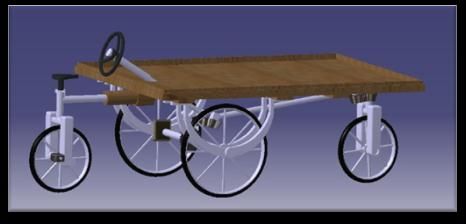
International Research Journal of Engineering and Technology (IRJET)                                    e-ISSN: 2395-0056
         Volume: 09 Issue: 04 | Apr 2022             www.irjet.net                                             p-ISSN: 2395-0072

modification has made this handcart more advanced. As per             a) Providing a steering mechanism.
this modifications and innovations it is decided to give the          b) Provision of seat along with paddling mechanism.
title to this project as “THE NEXT GENERATION HAND-                   c) Provision of braking.
KART”.
                                                                               For fulfilling the above objective, a design taken into
1.1 NEED OF THIS PROJECT                                              consideration is the conventional hand cart along with some
                                                                      changes. The major challenge to apply a steering mechanism
      For making farmers, goods sellers and vegetable                 to front two wheels, the front wheels are to be mounted
vendor’s life comfortable during work, we are transforming            independently so that a steering mechanism can be provided
the pushing handcart to riding handcart. This project will            with a linkage. The operation of steering mechanism is nice
make the changes in development field of engineering and              and smooth with perfection of turning sensitivity. Handle
give benefits to farmers and sellers and retailers. The old           provided is just like a handle of bicycle having provision of
mechanism of hand pushing trolley or cart is very hard to             hand brake and horn the paddling mechanism was also
push and walk along with the trolley till the destination. We         provided on rear wheels of cart. However, it uses the fifth
are fabricating the next generation riding trolley. On this           wheel during paddling which makes the operation complex.
trolley the seller can keep eye on the products in front of him
and thus the chances of theft are reduced.                                     The seating position of driver is outside the cart
                                                                      trolley (i.e. some inches away from the rear wheels shaft)
         From this project the vendors will get relief from           that offsets the driver weight from rear axle making the cart
walking along with hand cart for selling their products and           tilt. For overcoming this issue, a fifth wheel has been
they will spot the products and items in front of them while          provided that makes the cart unnecessary heavy and
riding the trolley and they can produce free electricity from         creating more resistance during paddling. Though the
the power generating mechanism which is mounted on this               steering mechanism is sensitive independent axle front
hand-cart. They will ride trolley with less effort and force          wheels give effective steering of hand cart. Some other issues
and from that they will get health benefits too.                      which are not addressed in the existing design are,

1.2 THE NEXT GENERATION HANDKART                                        1) Security and Safety; needs more attention on those
                                                                           issues.
          To give relief to the vendors from walking along
together with the trolley and keep eye on their products we             2) Hygiene; the cart is open during the use; this leads to
are introducing the next generation hand kart where we are                 unhygienic conditions.
connecting steering mechanism for front wheel to give
                                                                        3) Aesthetic consideration in design so that it looks
turning movement to the trolley by using bevel gear
                                                                           smart.
mechanism and attaching bicycle gears to the rear wheel of
the bicycle. We are connecting rear wheel of bicycle to rear            4) Efficient paddling, the efforts taken during the
side of the cart for transmitting the power to ride the trolley            paddling are more and there is unnecessary increase
with less efforts. The trolley we are making by using Ball                 in cost due to provision of fifth wheel.
bearings, Bevel gears, Connecting rod, trolley frame, trolley
wheel, Sprocket, Steering, pedals, seat, brakes, etc. The               5) Ergonomics, which can make the use of cart more
vendor will get amazing experience while riding and selling                comfortable and easier.
products.
                                                                           The survey has been conducted during this project; the
                  We are connecting power generation                  major requirement of hawkers was change of storage unit
mechanism to the cart which will generate the electricity             size and shape i.e. to be modular.
while cart is working or running. The generated electricity
will charge the battery and store the electricity in the                       The Market survey shows that the requirement of
battery. That stored electricity can used by the vendor at            storage space must be different for different purposes for
night to lighting up the cart and other uses.                         example the pani-puri stall needs wooden platform because
                                                                      steel get corroded due to acidic water of pani-puri and tea
2. LITERATURE REVIEW                                                  stall needs steel platform because of use of stove. So, the
                                                                      storage platform must be detachable from main chassis
2.1 Dissertation On Product Design Approach For Design                easily and also easily attachable One should take this
And Development Of “Hand-Cart” Submitted by Mr.                       modular approach on priority during modification of the
Satish P. Lokhande                                                    hand-cart. During this project some on standardization of
                                                                      dimensions proposed which would be modified as per
        This project is a successful attempt to modify a              design requirement.
conventional & “Hand- cart” The design and development
approach in this Project had major focus on the issues like

© 2022, IRJET        |     Impact Factor value: 7.529             |    ISO 9001:2008 Certified Journal              |   Page 3923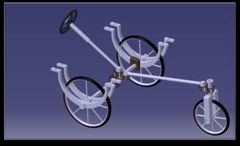
International Research Journal of Engineering and Technology (IRJET)                                       e-ISSN: 2395-0056
         Volume: 09 Issue: 04 | Apr 2022                www.irjet.net                                              p-ISSN: 2395-0072

2.2 “FOOT STEP POWER GENERATION” Submitted by                             4.1 STEPS INVOLVED
Sarat Kumar Sahoo, Shubham kumar, Pankaj Kumar
Yadav and Rishav Kumar

        In this project, electrical energy is generated by
means of a non- conventional method just by walking on the
footsteps. Non-conventional system for energies are very
much required at this time.

         Energy generation using footsteps has requires no
fuel input to generate electricity. In this project, electricity is
generated just with the help of rack and pinion arrangement
along with alternator and chain drive mechanism.

          For its proper functioning such that it converts
Force into electrical energy, the mechanism consists of rack
& pinion, chain drives, alternator and battery. We have
discussed its various alternate applications with extension
also. The power generation is much worthy but it has little
initial cost effective factors.

         Now, focusing on its working principle, this device if
embedded in footsteps of railway platforms, city malls, city
footpaths e.t.c. & can convert the weight impact of people
into electrical energy. When a pedestrian will step on the top
plate of this device, the plate will go down and this
downward motion results in rotation of the shaft of the
alternator which produces electrical energy. After removal of
force the top plate returns to its original position due to
springs.

3. OBJECTIVES
                                                                                                      Flow Chart-1
    1) To create a four-wheeled human-powered load-
       carrying cart assembly with an integrated steering                 4.2. MATERIAL SELECTION
       system.
    2) To develop a cart assembly that avoids the need to                          After doing research on the several material
       be lifted from behind when turning around a bend.                  properties, the most feasible material is selected for the Next
    3) To provide a cart assembly that allows heavy loads                 Generation Handkart. We investigated for the characteristics
       to be transported without causing strain or injury to              which are taken into account, which including machinability,
       the person operating the cart whenever turning the                 durability, strength, weight, availability, and material cost. A
       cart over curves.                                                  material with sufficient strength is chosen to ensure that the
    4) To furnish a four-wheeled, human-powered load-                     frame of the Next Generation Handkart does not fail under
       carrying cart assembly with good maneuverability                   the strain exerted. Cast iron alloy has been used for this
       and control on uphill surfaces and curves.                         project.
    5) To add a structurally simple and cost-effective
       enhancement to the current hand-cart that allows it                5. MODELLING
       to be steered without any further physical effort.
                                                                          5.1 CATIA V5
4. METHODOLOGY
                                                                                   The virtual model is created by using CATIA V5
          A methodology for pedalling, steering, and power                modelling software to analyze the model. The dimensions
generation mechanism of the Next Generation Handkart                      are considered as per the physical model and a rough
based on man powered which has been facilitated to move is                diagram of the Next Generation Handkart is drawn with
demonstrated. This chapter also describes material selection              designed handcart pattern, then in Catia V5. With the help of
based on technical factors that made the material eligible for            workbench a cross section is drawn using basis tools like
utilization.                                                              spine, mirror, line, circle, trim and after that by using tools
                                                                          like pad, chamfer, revolve and hole to create a 3D model.

© 2022, IRJET          |    Impact Factor value: 7.529                |    ISO 9001:2008 Certified Journal              |   Page 3924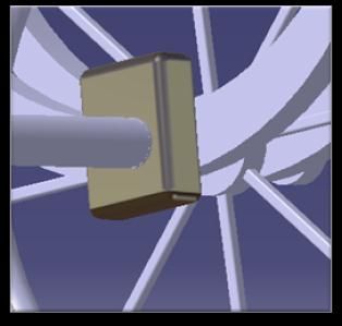
International Research Journal of Engineering and Technology (IRJET) e-ISSN: 2395-0056
Volume: 09 Issue: 04 | Apr 2022 www.irjet.net p-ISSN: 2395-0072
5.2 CATIA MODELLING
Fig. 01: 3D View of Handkart
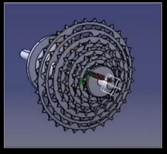
Fig. 05: 7 Speed Bicycle Gears
Fig. 06: Multi-View
Fig. 02: Steering Mechanism
6. DESIGN
The design of handcart was primarily divided into following
aspect of design;
1. Kinetic Design
2. Kinematic Design
Following are the details of each design.
6.1 KINETIC DESIGN
The design of Kinetic is “of our relating to the
motion of material bodies and the forces and energy
associated therewith”. So, the kinetic design means designing
the motion, and calculating forces & energy required to pull
Fig 03: Uni-Cycle
or push the cart taking into consideration the load on
vehicle. In the project following are the calculations of the
wheel forces, rolling friction of bearing, the force used by
driver (man).
A man can push 227 N [1] in the seated position and 251 N
[2] in the standing position at his max potential.
6.1.1 ROLLING FRICTION (Fr)
The standard wheel size of handcart [3]
Wheel diameter = 70cm = 700mm = 0.7m
Radius of wheel = 0.35m
Fig 04: Power Generating Mechanism
© 2022, IRJET | Impact Factor value: 7.529 | ISO 9001:2008 Certified Journal | Page 3925
International Research Journal of Engineering and Technology (IRJET)                             e-ISSN: 2395-0056
           Volume: 09 Issue: 04 | Apr 2022         www.irjet.net                                            p-ISSN: 2395-0072

M = Overall weight                                                Bearing Designation : 6302.

    1.     Considering live load on cart (200Kg)                  6.2 STRUCTURAL DESIGN
    2.     Considering weight of man (100Kg)
                                                                  It is assumed that the 200kg load is uniformly distributed
W=m×g                                                             across the entire handcart.

   = 300 × 9.81                                                   Finding stress induced in frame under loading.

   = 2943 N                                                       Assume frame been under UDL.

H(height) = 0.3m ……………{Assumed}                                   To find the reaction at A & B

Fr = N × µ × b / √r2 – b2                                         Assume ∑Fy = 0 (↑ +ve, ↓ -ve)

Where;                                                            RA + RB – 1962       1.6 = 0

Fr – Rolling Friction                                             RA + RB = 3139.2 N
N – Reaction at tangent                                           ∑M = 0 (⥀ +ve, ⥁ -ve)

µ - Coefficient of Friction                                       Taking moment at point A

b – Surface in contact = 0.03m                                    -RB    0.8 + (1.6    1962)     0.4 = 0

 Fr =                                                             RB = 1569.6 N

                                                                  RA = 3139 – 1569.6
Fr = 75.97 ~ 76 N
                                                                  RA = 1569.6 N
Hence, the force required to keep the cart rolling is 76 N.
                                                                  RA = RB = 1569.6
6.1.2 BEARING DESIGN
The bearing is subjected to pure radial load

Radial Force (Fr) = 1962N

N = 80rpm

Life (L) = 30000hrs

Shaft diameter (d) = 15mm
                                                                                      Fig 4.1: BEAM DIAGRAM
Bearing life million revolution:
                                                                  6.2.1 SF CALCULATION :
L10 = 60     N(L10) hr/106
                                                                  SF at point C = 0
= 144 million rev.
                                                                  SF just at the left of point A = - 1962   0.4 = -784.8 N
Dynamics load carrying capacity (C)
                                                                  SF at point A = -784.8 + 1569.6
C = p(L10) ⅓
                                                                                = 784.8 N
  = 2943      (144) ⅓
                                                                  SF just at the left of point B = 784.8 – 1962       0.8
C = 15425.68 ≈ 15426 N
                                                                                                    = 784.8 N
Hence as we got C = 15426 N
                                                                  SF at point D = 784.8 – 1962      0.4
From Manufacturing Catalogue;
                                                                              =0N
© 2022, IRJET           |     Impact Factor value: 7.529      |    ISO 9001:2008 Certified Journal                |    Page 3926
International Research Journal of Engineering and Technology (IRJET)                                e-ISSN: 2395-0056
         Volume: 09 Issue: 04 | Apr 2022             www.irjet.net                                           p-ISSN: 2395-0072

To find the point of zero shear;

     ==

           = (x – 0.4)

x = 0.8m

6.2.2 BM CALCULATION

BM at the point of zero shear

Zero shear is at x – x section at x = 0.8

BM at x – x = RA     (x – 0.4) – 1962      x

              = 1569.6 (0.8 – 0.4) – 1962
                                                                                     FIG. 6.2: SF & BM DIAGRAM
              =0
                                                                  When x = 0.4; y = 0
BM at x – x at zero shear = 0
                                                                  C2 = 115.104
BM calculation for other points
                                                                  M = 1569.6               +           + 292.992
BM at C = 0 (⥀ +ve, ⥁ -ve)

BM at A = -1962          x                                        Put x = 0.8

                                                                  M = 585.984
BM at A = -1962
                                                                  For I of L section;
At x = 0 → BM = 0                                                 The area (A) = (h + b - t)

At x = 0 → BM = -1962                                                           = (40 + 40 - 10)      10

BM = -156.96                                                                    = 700 mm2

BM at B = RAx (x2 – 0.4) -1962         x                          Perimeter (P) = 2b + 2h

                                                                                =2      40 + 2   40
At x2 = 0.4

BM = -156.96                                                                    = 160 mm

At x2 = 0.8                                                       The distance of the centroid from the left edge of the section
                                                                  (xc), and from the bottom edge (yc), can be found using the
                                                                  first moments of area of the two legs:
BM = 1596.6      (1.2 – 0.4) -1962
                                                                  xc = ( (h2 + ht – t2))
BM = -156.96

BM at D = 0                                                       xc = 13.5714 mm

                                                                  yc = ( (h2 + bt – t2))

                                                                  yc = 13.5714 mm

© 2022, IRJET                |   Impact Factor value: 7.529   |      ISO 9001:2008 Certified Journal               |   Page 3927
International Research Journal of Engineering and Technology (IRJET)                                 e-ISSN: 2395-0056
          Volume: 09 Issue: 04 | Apr 2022              www.irjet.net                                          p-ISSN: 2395-0072

The moments of inertia Ix0, Iy0 & Ix0y0 of the angle section         7. WORKING AND MODIFICATION
around the x0 and y0 axis are:
                                                                               To alleviate the hardship of walking with a handcart
          Ix0 = (bt2 + h3 – t3)                                      while somehow providing a safety aspect, we modified the
                                                                     conventional handcart to make the necessary improvements.
             = 223.33          103 mm                                The power transmission is provided by the unicycle, which is
                                                                     mounted to the rear portion of the handcart. The source of
                                                                     power transmission is the paddle mechanism, which drives
          Iy0 = (ht2 + b3 – t3)
                                                                     the unicycle's wheel and generates pushing force for the
                                                                     handcart, allowing it to move. A bicycle gear is connected to
             = 223.33          103 mm                                offer seven speeds to the handcart, to reducing the amount
                                                                     of effort required for pedalling. The seven-speed gear system
          Ix0y0 = (b2 + h2 – t2)                                     will aid in the operation of the handcart on incline surfaces
                                                                     such as hilly areas.
             = 77.5       103 mm
                                                                              The steering mechanism is given to provide relief
                                                                     from weight lifting when moving the handcart on the turning
          Ixy = Ix0y0 – Axcyc
                                                                     and to reduce traffic conditions on the highway caused by
  = (77.5       103) – (700       13.5714   13.5714)                 the handcart. The steering mechanism works similarly to
                                                                     that of a car, using bevel gears and a connecting rod. With
          Ixy = - 5142.8 mm4                                         the aid of the connecting rod, the bevel gears revolve in
                                                                     tandem with the steering wheel. As a consequence, the front
                                                                     wheel will get the turn moment needed to turn the next
          Y=
                                                                     generation handkart on the road.

            =                    ………Esteel = 200GPa                            The power producing mechanism is now positioned
                                                                     parallel to the wheel as the following change. The DC motor
                                                                     houses the power generation mechanism. The sprocket is
          Y = -5.69       10-8 mm
                                                                     connected to the shaft of the DC motor. The sprocket is
                                                                     attached to the wheel, and when the handcart moves, the
          Now from flexure formula,
                                                                     wheel rotates, causing the shaft of the DC motor to revolve
                                                                     counter-clockwise. As a result, the DC motor will function as
            =    →    =
                                                                     a power generator, producing electrical energy. The
                                                                     electrical energy will be stored in the battery for future free
                                                                     electricity usage.

                                                                              The handcart is equipped with brakes for optimum
                              10-10 N/mm2
                                                                     safety. The brakes are attached to the wheel of the handcart,
                                                                     and when the brakes are applied, the rate of velocity
6.2.3 Bevel gear ratio
                                                                     decreases until it reaches zero, at which point the handcart
N1 = 54                                                              stops. The brake lock also provided to keep the handcart
                                                                     stable or motionless.
N2 = 108
                                                                               Radium stickers are applied on the handcart's
N1 : N2 = 54 : 108                                                   exterior surface for safety reasons. As a result, in a dark
                                                                     night scenario, the beams of light from other vehicles
          =1:2                                                       approaching the handcart will be incident on the surface of
                                                                     the radium sticker, allowing it to glow. As a consequence,
Where,                                                               other vehicles will see the handcart in the dark night, which
                                                                     will aid in saving the handcart from an accident.
N1 = Number of teeth on driven gear
                                                                     8. FABRICATION
N2 = Number of teeth on driving gear
                                                                              Following the selection of materials that are light in
That is, if the driven gear is meshed to the driving gear            weight, durable, and readily available, such as cast iron alloy,
installed on the front wheel. If the driven gear completes one       teak wood, and steel alloy. Several machining processes are
revolution, the driving gear rotates 180° within the                 performed on the material. Clamps, steering wheels,
revolution.                                                          supports, Bevel gear frames, and other elements are

© 2022, IRJET             |     Impact Factor value: 7.529       |     ISO 9001:2008 Certified Journal             |   Page 3928
International Research Journal of Engineering and Technology (IRJET) e-ISSN: 2395-0056
Volume: 09 Issue: 04 | Apr 2022 www.irjet.net p-ISSN: 2395-0072
manufactured. In the fabrication, we do cutting, drilling, lock functions. With the assist of a DC motor, this handcart
welding, milling and shaping operations. Other operations may produce free electricity from the movement of the
on supports include a groove for the bevel gear frame and a wheel.
grove on the support plate. Bench-wise clamping is used to
prepare the clamps. A lathe machine is used to prepare the 12. FUTURE SCOPE
bevel gear frame. Following the fabrication of all pieces, they
are assembled into the Next Generation Handkart utilising Furthermore, if the pedalling mechanism fails, it
cutting and welding operations. may be powered by a battery-driven electric drive charged
by a solar panel. This "The Next Generation Handkart" will
9. Advantages be upgraded into an autonomous hand-cart with a safe anti-
thief system in the future. It will reduce the amount of
1. Vendors may sell their wares under their
manual work required and, most likely, popularise the
supervision.
design. When necessary, a reverse gear also provided.
2. Vendors will be relieved of the hassle of travelling
with the handcart. 13. ACKNOWLEDGEMENT
3. Vendors will be relieved of their heavy peddling. We express our heartiest acknowledgement to all
4. Vendors can use brakes to slow down their those who supported us and provided valuable guidance
handcarts. whilst completion of this project. We would like to take this
opportunity with great pleasure to express our deep sense of
5. The merchants can use the hand brake to keep their gratitude towards our guide Prof. Pravin D. Padole for his
handcart in place. valuable guidance and incessant encouragement and co-
6. Vendors can direct the handcart in the desired operation extended to us during this dissertation work. We
direction. would like to say special thanks to our Hon. Head of
Mechanical Department, Dr. Pravin A. Potdukhe and the in-
7. The venders will receive free electricity. charge of workshop Shri. Thamke sir for giving us their
valuable time.
8. Safety criteria such as radium stickers, brakes, and
so on are furnished.
14. REFERENCES
10. Disadvantages
[1] Gavriel Salvendy; Handbook of Human Factors &
1. The method for generating electrical power is Ergonomics; 46 Edition; © John Wiley & Sons, Inc.,
dependent on the speed of the handcart. 2012.
2. The effort required to pedal and the velocity factor
are directly proportional to the weight of the [2] Gnanvel Chokkalingam, Gopalalcrishnan T,
handcart. Sivaganesan Selvaraju; Design & Fabrication of
Pedal Powered Stair Climbing Trolley; DOI:
3. Lubrication is necessary. 10.23883/ffrter.2018.4153.Afiwg; March-2018.
4. Maintainance required.
[3] Sun, Yun ; Effects of Load & Gradient on
11. CONCLUSION Musculoskeletal Loading During Dynamic Two
Wheeled Cart Pushing &Pulling ; Graduate Theses ,
The Next Generation Handkart has been successfully Dissertation & Problem Reports 4801; 2011.
designed, and it has the capacity to carry an average of 200 https://researchrespository.wvu.eduietd/4801.
Kg of load or items that can be sold under the vendor's
supervision. This handcart is more efficient than a [4] CCOHS: Pushing & Pulling Handcarts'
traditional handcart. Vendors will be relieved of the burden https://www.ccohs.ca/
of trekking kilometres with a handcart to sell their stuff.
They can turn the handcart in the desired direction with the [5] https://www.quickcompany.in/patents/improved-
help of steering. hand-cart-haath-thela#documents
The bicycle gear is also installed or mounted on the [6] Ergonomic & Fe Analysis of Smart Hand Cart W. S.
rear wheel to make the pedal mechanism smooth and batter. Sheikh, B. B. Babre:
This handcart can be driven with little effort by the vendor.
This Next Generation Handkart includes built-in safety http://iosrjen.org/Papers/Conf.ICMPIR-
measures such as brakes, radium stickers, a horn, and brake- 2019/Volume-10/10,%2048-50.pdf
© 2022, IRJET | Impact Factor value: 7.529 | ISO 9001:2008 Certified Journal | Page 3929International Research Journal of Engineering and Technology (IRJET) e-ISSN: 2395-0056
Volume: 09 Issue: 04 | Apr 2022 www.irjet.net p-ISSN: 2395-0072
15. BIOGRAPHIES
Prof. Pravin D. Padole, Guide of project “The
Next Generation Handkart” and Associate
Professor of Department of Mechanical
Engineering at Rajiv Gandhi College of
Engineering Research and Technology,
Chandrapur, Maharashtra. They having 28
years of teaching experience.
Mr. Nayan S. Soni, Project leader of “The Next
Generation Handkart”. He is currently
pursuing final year of Bachelor of
Technology in the Mechanical Engineering at
Rajiv Gandhi College of Engineering
Research and Technology, Chandrapur,
Maharashtra. Aside from that, he is a
researcher and innovator with enthusiasm
and strong analytical skills he wishes to
explore more about cloud computing and
related services such as IBM Cloud and AWS.
Mr. Meghraj Gowardhan, currently pursuing
final year of Bachelor of Technology in the
Mechanical Engineering at Rajiv Gandhi College
of Engineering Research and Technology,
Chandrapur, Maharashtra. with the technical
knowledge he eager to work in automobile
industry.
Mr. Manish Sonkusare, currently pursuing
final year of Bachelor of Technology in the
Mechanical Engineering at Rajiv Gandhi
College of Engineering Research and
Technology, Chandrapur, Maharashtra. He is
also detail-oriented, precise, and has
expertise doing technical designs.
Mr. Umesh Nannaware, currently pursuing
final year of Bachelor of Technology in the
Mechanical Engineering at Rajiv Gandhi
College of Engineering Research and
Technology, Chandrapur, Maharashtra. Apart
from that He aims to obtain a deeper
understanding of various automobile
technologies by using his expertise and
talents.
© 2022, IRJET | Impact Factor value: 7.529 | ISO 9001:2008 Certified Journal | Page 3930You can also read