TECHNICAL PAPER TRACS JIP - TTR Life Extension Process - OTC August 2021 - 2H Offshore
←
→
Page content transcription
If your browser does not render page correctly, please read the page content below
TECHNICAL PAPER

TRACS JIP - TTR Life Extension
Process
Dhyanjyoti Deka, Mike Campbell - 2H Offshore, Vinayak
Patil - Clarus Subsea Integrity, Michael Long Ge - BP,
Steve Wong – Shell, Tim Frame - Occidental Petroleum

OTC
August 2021
OTC-31060-MS

TRACS JIP – TTR Life Extension Process

Dhyanjyoti Deka and Mike Campbell, 2H Offshore, Inc; Vinayak Patil, Clarus Subsea Integrity; Michael Long Ge,

                                                                                                                                                                            Downloaded from http://onepetro.org/OTCONF/proceedings-pdf/21OTC/3-21OTC/D032S085R006/2470503/otc-31060-ms.pdf by Dhyan Deka on 04 October 2021
BP America Production Co.; Steve Wong, Shell; Tim Frame, Occidental Petroleum

Copyright 2021, Offshore Technology Conference

This paper was prepared for presentation at the Offshore Technology Conference held in Houston, TX, USA, 16 - 19 August 2021.

This paper was selected for presentation by an OTC program committee following review of information contained in an abstract submitted by the author(s). Contents of
the paper have not been reviewed by the Offshore Technology Conference and are subject to correction by the author(s). The material does not necessarily reflect any
position of the Offshore Technology Conference, its officers, or members. Electronic reproduction, distribution, or storage of any part of this paper without the written
consent of the Offshore Technology Conference is prohibited. Permission to reproduce in print is restricted to an abstract of not more than 300 words; illustrations may
not be copied. The abstract must contain conspicuous acknowledgment of OTC copyright.

Abstract
The Tensioned Riser Assessment for Continued Service (TRACS) JIP develops a structured life extension
process for TTR systems including single casing, dual casing, buoyancy can supported and tensioner
supported TTRs. The JIP bridges regulatory and API frameworks and achieves industry consensus on
analysis, inspections, and documentation.
   The life extension process developed in this JIP consists of detailed roadmaps that guide the operator
through the different assessment steps starting from initial data gathering through to the development of
the forward-looking IMP. The JIP life extension process is based on a threat assessment philosophy which
ensures identification and assessment of all possible threats to the integrity of the TTR in its extended life.
   The JIP process is validated against three real life TTR systems that are nearing the end of their design
lives. Potential threats to the integrity of these TTRs during the projected continued service beyond the
design life are identified and specific inspection and analysis recommendations to safely manage or mitigate
these threats are made.
   The JIP also provides TTR life extension analysis guidance while considering the opportunities to reduce
conservatism compared to new designs. Inspection of TTRs is challenging due to accessibility issues and the
pipe in pipe construction. Several subsea NDE inspection tools are surveyed in this JIP and their applicability
to TTRs is discussed.

Introduction
Top tensioned risers are widely used in the deep-water offshore industry. Over 300 TTRs were installed
worldwide prior to 2004 with an average design life of 20 years. Many of these risers are coming to the
end of their design lives and operators must decide whether to continue using these risers or decommission
them. Often, the wells keep producing beyond their original design lives and a life extension (or continued
service) assessment to verify fitness for extended service of these TTRs is necessary.
   Offshore asset life extension is not as novel of a concept as it was a decade ago. However, there is limited
experience in the industry when it comes to TTR life extension. To confidently operate a TTR beyond its
design life, a substantial amount of rigor is essential in the fitness assessment. TTRs provide direct vertical
access to the well and hence, failure of barriers can lead to severe human and environmental consequences.
TTRs are also complex systems with several constituent components and some of these components are
                              Learn more at www.2hoffshore.com
2 OTC-31060-MS
not easily accessible for direct visual inspection, for example the keel joint. Each component has its own
set of design, fabrication and operational data that needs to be considered in the life extension assessment.
In addition, there are no existing codes or guidance documents on this topic. Therefore, the onus is on the
industry to develop a practical but thorough life extension process that will provide confidence both to the
operators and the regulatory body.
The TRACS JIP develops detailed roadmaps for assessing the threats relating to life extension of TTRs
and addresses the mitigation of potential risks. The JIP uses data from participant-supplied case studies
to validate the roadmaps and provides documented examples for future guidance. The goal of the JIP is
to bridge BSEE and API frameworks and achieve industry consensus on analysis and inspection data and
Downloaded from http://onepetro.org/OTCONF/proceedings-pdf/21OTC/3-21OTC/D032S085R006/2470503/otc-31060-ms.pdf by Dhyan Deka on 04 October 2021
documents required to assess the life extension feasibility of TTRs.
TTR System Description
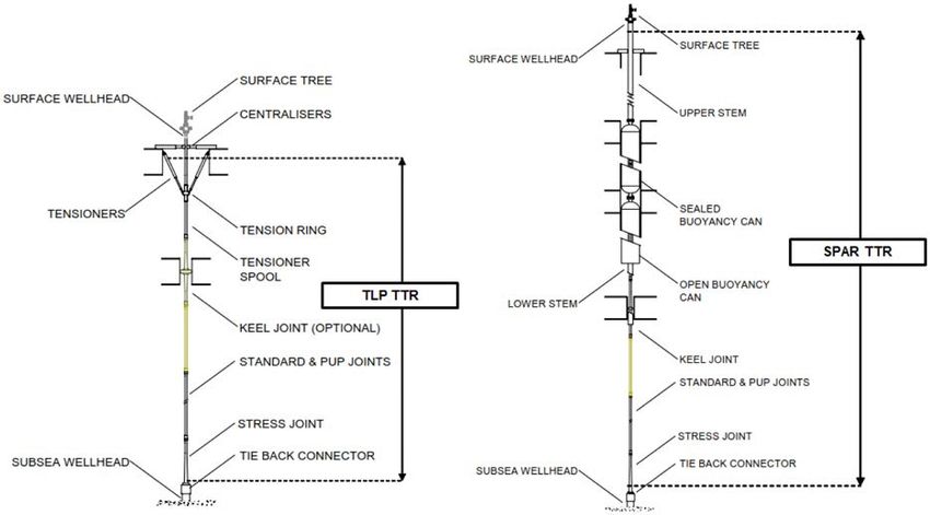
Top tensioned risers are designed to provide surface access to wells in a manner analogous to fixed platforms.
TTRs are typically used with two floater types: TLPs and spars. General TLP and spar TTR configurations
are shown in Figure 1. The two TTR configurations are almost identical below the floaters. The difference
is in the support and tensioning at the top. The TLP TTRs are supported using hydro-pneumatic tensioners
while the spar TTRs are typically tensioned using non-integral buoyancy cans (sometimes called air cans).
The following components constitute a TTR system starting from mudline up to the vessel:
• Tieback connector;
• Stress joint;
• Riser joints and connectors;
• Tensioners (for all TLP TTRs);
• Keel joint, lower stem, buoyancy cans, upper stem (for most spar TTRs);
• Surface tree;
• BOP if the TTR is being used in workover or drilling mode;
• Flexible jumpers.
Learn more at www.2hoffshore.comOTC-31060-MS 3
Downloaded from http://onepetro.org/OTCONF/proceedings-pdf/21OTC/3-21OTC/D032S085R006/2470503/otc-31060-ms.pdf by Dhyan Deka on 04 October 2021
Figure 1—Typical Spar and TLP TTR Configurations
TTRs can either be single casing consisting of the outer casing and production tubing or dual casing
which consists of an additional inner casing between the outer casing and production tubing.
TTR Life Extension Process
The TRACS JIP TTR life extension process is summarized in broad steps in Figure 2. Each step in this
figure is composed of multiple smaller steps which have not been shown for the sake of brevity. The
methodology is based on a threat identification and mitigation philosophy. Key threats applicable to the
different components of the TTR system in its extended service life are identified and continued service
assessment of each threat is performed based on data and analysis. The JIP uses elements of API RP
2RIM (2019) to help define data gathering, integrity review, inspections, and IMP development tasks. The
following sections describe the broad stages of the TTR life extension process.
Learn more at www.2hoffshore.com4 OTC-31060-MS
Downloaded from http://onepetro.org/OTCONF/proceedings-pdf/21OTC/3-21OTC/D032S085R006/2470503/otc-31060-ms.pdf by Dhyan Deka on 04 October 2021
Figure 2—TTR Life Extension Methodology
TTR Threat Identification
The JIP compiles a comprehensive list of age-related threats to the integrity of a TTR in its extended life.
Both spar and TLP TTRs threats are included. The threats are classified into two types – fatigue related, and
wall loss related. Fatigue threats are caused by cyclic stresses which if unchecked, will lead to uncontrolled
crack propagation and ultimately failure of the pipe or component. Fatigue threats typically require a global
fatigue analysis-based evaluation. Some examples of fatigue threats are:
• Loss of centralization of the inner casing;
• TTR being operated at a lower tension than design limits;
• Loss of VIV suppression devices.
The wall loss threats relate to loss of pipe wall thickness which can in turn lead to fatigue, strength, burst
or collapse failure. Wall loss threats may require MAOP re-calculations, strength analysis checks or ECA.
Examples of wall loss threats are as follows:
• External corrosion wall loss;
• Wear related wall loss;
• Service change leading to unfavorable internal condition.
Integrity Data Review
Each identified threat is assessed for criticality based on design, fabrication, installation, inspection,
monitoring and maintenance records, collectively termed as integrity data. The JIP identifies specific data
sources for each threat to facilitate the life extension process. For example, top tension records or buoyancy
pressure data are key in assessing TTR compression related threats or stress joint fatigue related threats.
The following set of data is typically needed to ascertain the design limits of the TTR and to assess its
condition at the time of installation:
• Design basis;
• Design analysis reports;
Learn more at www.2hoffshore.comOTC-31060-MS 5
• Riser and component specifications;
• Fabrication drawings;
• As-built drawings;
• Welding procedure specifications;
• As-built installation survey data;
• Independent verification reports.
Downloaded from http://onepetro.org/OTCONF/proceedings-pdf/21OTC/3-21OTC/D032S085R006/2470503/otc-31060-ms.pdf by Dhyan Deka on 04 October 2021
In addition to understanding the design limits, the life extension assessment must also take the TTR
operational history into account. Typical operational data that are collected are as follows:
• Pressure, temperature data;
• External visual reports (for mechanical damage, marine growth and VIV suppression device
condition);
• Top tension measurements;
• Production chemistry;
• Annulus pressure data;
• Tensioner pressure and stroke data;
• Vessel and riser motion data;
• Measured wave heights and current speeds.
Towards the end of design life, which is when life extension assessments are usually conducted, not all
this data may be available. In lieu of missing data, surveys and inspections of the TTR may be conducted.
Data gaps can also be filled with appropriate assumptions while considering the uncertainties in the specific
parameter of interest.
TTR Inspections
Inspections are an integral part of the TTR life extension process. TTR threats are assessed based on recent
inspection data including general and close visual inspections, CP/anode surveys and NDE.
Above-water and below-water visual, splashzone and CP inspections are routinely performed while in
service. However, NDE tools geared towards inspection of pipelines may not be feasible for TTRs due to
the pipe in pipe construction and absence of pigging loops.
In-service inspection is defined as inspection of the riser while remaining in-service, regardless of
product flow. In this method, NDE and/or NDT methods are used to identify any need for refurbishment
or replacement of components. Out-of-service inspection refers to inspection of a riser after it has
been removed from the water and delivered onshore. In this method, NDE is used to identify need for
refurbishment or replacement of components. An out-of-service inspection is generally not feasible for a
production TTR. The TRACS JIP surveyed several existing NDE tools for potential application on TTRs
while in service. The JIP provides participants with the following information on 20 subsea tools:
• NDE technology type – UT, ToFD, Phased Array, CT, MEC, PEC, ACFM or EMAT;
• Type of feature detected - wall thickness loss, corrosion defects or cracks;
• Potential application location - outer casing, inner casing or buoyancy can;
• Scanning speed;
Learn more at www.2hoffshore.com6 OTC-31060-MS
• Specifications - OD, wall thickness ranges, PoD;
• Day rates;
• Level of preparation required such as calibration or dredging.
Every tool has its own advantages and disadvantages and there is no single tool that can inspect the
entirety of the TTR. It is expected that a combination of tools may be used in a TTR life extension inspection.
For example, one of the enabling technologies is Computed Tomography. The CT instruments can provide
detailed cross-section mapping of the outer casing as well as inner casing. However, these instruments can
Downloaded from http://onepetro.org/OTCONF/proceedings-pdf/21OTC/3-21OTC/D032S085R006/2470503/otc-31060-ms.pdf by Dhyan Deka on 04 October 2021
be bulky and slow and hence, it is useful to determine the critical sections beforehand using a fast scanning
tool. UT tools can detect cracks. However, there are challenges with respect to inspection through coatings
and in deepwater. UT can be used in conjunction with PEC or CT.
BSEE (2015) does not prescribe which NDE method to use nor does it require the operator to inspect for
cracks in addition to wall loss and corrosion defects. BSEE leaves the selection of an appropriate NDE tool
and inspection acceptance criteria to the operator. The TRACS JIP survey gives operators a running start
with regards to TTR life extension NDE inspection.
Condition Assessment
The current condition of the TTR system is determined based on the review of the integrity data and
supplemental baseline inspections. The condition assessment accounts for any damage, repair, or other
factors that could potentially affect the TTR's fitness for life extension. The TTR condition assessment
report feeds into the design basis of the life extension analysis. The condition assessment report may include
information such as follows:
• Riser age, condition, and original design criteria;
• Internal fluid characteristics – pressure, temperature, fluid chemistry (e.g. presence of H2S or CO2),
sand content, water cut;
• TTR annulus condition;
• Platform motions;
• Metocean data – hindcast or measured;
• Analysis results and assumptions made in the original design or subsequent assessments;
• In-service inspection findings;
• Riser modifications, additions, and repairs;
• Riser condition after an accidental loading, extreme metocean event (e.g. hurricane, high current
event);
• Status of the cathodic protection system;
• Riser monitoring data.
Life Extension Analysis
The life extension fitness for service assessment quantitatively determines whether the riser has the fatigue
capacity for continued service. A refined fatigue/corrosion assessment may be conducted that utilizes
the latest industry standard software tools, analysis methods, and an understanding of the conservatism
involved in typical riser design fatigue analysis. As stated in the previous section, the analysis models should
incorporate the current condition of the riser including any gaps such as missing centralizers, reduced wall
Learn more at www.2hoffshore.comOTC-31060-MS 7
thickness, presence of corrosion or missing VIV suppression. For GoM projects, the analysis is conducted
per API RP 2RD (2009) with a fatigue factor of safety equal to 10.
The fitness for service assessment is stepwise and simple assessments are conducted first. Refined
assessments that may require complicated analysis or testing are used only if necessary. In some instances,
analysis may not even be necessary. If the TTRs were operated within the prescribed design limits and
environments did not exceed design conditions and the extended service life is not greater than the calculated
original fatigue life, life extension feasibility can be established without any additional analysis.
While not a requirement, life extension analysis may be conducted in two phases so that the analysis
can take advantage of reduced uncertainties in the first phase. The first phase represents the time from
Downloaded from http://onepetro.org/OTCONF/proceedings-pdf/21OTC/3-21OTC/D032S085R006/2470503/otc-31060-ms.pdf by Dhyan Deka on 04 October 2021
installation till the end of original design life. The second phase represents the extended service life starting
from the end of original design life till the end of extended life. If suitable records exist, the phase 1 analysis
can take advantage of known historical data such as measured wave heights, current speeds, actual marine
growth levels, corrosion wall loss, annulus conditions and top tension history. Several of the original design
level conservatisms may be reduced in phase-1 if those conservative assumptions were used to account for
data uncertainties which are no longer relevant. Phase-2 analysis is conducted akin to a new design analysis
using predicted future metocean conditions.
The design basis may be updated during the life extension assessment if additional refinements are
required to determine feasibility of extended service life. The fatigue SN curve/SCFs may be updated
based on additional tests. Additional VIV suppression may be retrofit on the riser. Riser monitoring may be
conducted for 1 – 2 years and a calibrated riser model may be developed based on the monitoring data.
Repairs and Replacement
The TRACS JIP recommends repair or replacement of joints and components if the condition assessment
and riser analysis determine that life extension threats cannot be mitigated by the current riser configuration.
The JIP progresses from the simplest and most economical repair solution to major repairs or replacement
programs based on necessity. In-service repair solutions such as addition of strakes or anode sleds are
preferable to replacement of joints. TTR repair and replacements that may be necessary at the time of life
extension are as follows:
• Marine growth cleaning of strakes and fairings;
• Installation of retrofit VIV suppression devices;
• Coating repair;
• Anode retrofit;
• Weld repair;
• External corrosion repair;
• Buoyancy can fill lines repair and replacement;
• Installation of clamps to immobilize damaged areas;
• Tensioner cylinder replacement;
• Riser joint replacement.
IMP Development
BSEE requires that all operators have an active IMP in place for risers that have undergone a life extension
assessment and are operating beyond their design lives. If the asset operations already followed an IM
program, the current IMP should be updated for threats identified during the life extension assessment.
Learn more at www.2hoffshore.com8 OTC-31060-MS
If the asset did not previously follow an active IM program, the foundations for a successful IM program
are developed. This may include setting up operational plans, maintenance plans, corrosion control plan,
anomaly handling plan and a description of roles and responsibilities. As part of the life extension process,
baseline inspections would have already been conducted which will help in the IMP development.
The TRACS JIP provides detailed roadmaps for development of both completely new IMPs as well
as update of existing IMPs. The continued service IMP roadmaps are based on recommendations in API
RP 2RIM (2019). The IMP is recommended to have provisions for monitoring of riser condition, visual
inspections, corrosion tests, top tension measurements, tensioner system maintenance, casing pressure
monitoring and CP measurements at minimum.
Downloaded from http://onepetro.org/OTCONF/proceedings-pdf/21OTC/3-21OTC/D032S085R006/2470503/otc-31060-ms.pdf by Dhyan Deka on 04 October 2021
Case Studies
The JIP uses data from 3 participant-supplied case studies (GoM TTR systems) to validate the life extension
process and provide documented examples for future guidance. The assessments include identification
of threats, review of integrity data corresponding to each threat and comparison of the data with design
limits. The JIP scope does not include riser analysis. However, specific recommendations for analysis and
inspections are provided. The results of these case study assessments can be used to execute the life extension
programs of these assets. The case studies can also be used as a reference for other TTR systems.
The identified threats are classified as either fatigue or wall loss threats. The threats are also placed in
red, orange, and green categories based on the system shown in Table 1.
Table 1—Categorization of Threats for the Case Studies
A total of 25 green threats are identified across the 3 TTR systems. A common green threat is top
tensions being outside the design ranges. However, this threat is well managed in each system with suitable
safeguards in place. There are provisions in the operating manual to air up the buoyancy cans whenever top
tension measurements fall below allowable values. For one of the TTR systems, the JIP determined that
chronic low top tensions are caused by faulty load cells.
No red threats are found in any of the TTR case studies which implies that the asset integrity management
programs of the 3 TTR systems are doing their job. A total of 13 orange threats are identified across the
3 TTR systems. As an example of an orange threat, the buoyancy can compliant guides of one of the spar
TTRs could not be inspected in recent campaigns due to excessive marine growth. The JIP identifies the
threat of compliant guide failure as an orange risk and makes additional marine growth cleaning and indirect
monitoring-based inspection recommendations.
Conclusion
The TRACS JIP develops a detailed life extension process for TTRs. The JIP recognizes that there are
no existing industry wide TTR life extension codes or guidelines. The JIP pools experience from major
GoM operators and bridges BSEE requirements and industry standards to develop a practical assessment
Learn more at www.2hoffshore.comOTC-31060-MS 9
procedure for TTR life extension assessment. The JIP process identifies the least complicated and most
cost-effective route to ensuring fitness for continued service of the TTRs.
The JIP uses participant supplied real life TTR system data to validate the life extension process.
Several potential age-related threats are identified for these TTR systems, most of which have already been
accounted for in the asset IM programs. Additional inspection, analysis and monitoring recommendations
are made for certain potential threats as appropriate. These case studies are useful in 2 ways – firstly, the
case studies progress the life extension assessments of these TTR systems and provide a running start to the
life extension project team. Secondly, these case studies are useful as templates for assessment of similar
TTR systems.
Downloaded from http://onepetro.org/OTCONF/proceedings-pdf/21OTC/3-21OTC/D032S085R006/2470503/otc-31060-ms.pdf by Dhyan Deka on 04 October 2021
The JIP provides technical and commercial information on 20 subsea NDE inspection tools to the
participants. It is understood that a combination of tools will likely be needed for TTR life extension
inspections. The JIP also provides life extension analysis guidance and identifies avenues to safely reduce
design level conservatism in the life extension analysis.
Nomenclature
ACFM = Alternating Current Field Measurement
API = American Petroleum Institute
BOP = Blowout Preventer
BSEE = Bureau of Safety and Environmental Enforcement
CP = Cathodic Protection
CT = Computed Tomography
ECA = Engineering Critical Analysis
EMAT = Electro Magnetic Acoustic Transducer
GoM = Gulf of Mexico
IMP = Integrity Management Plan
=JIP = Joint Industry Project
MAOP = Maximum Allowable Operating Pressure
MEC = Magnetic Eddy Current
NDE = Non-Destructive Examination
NDT = Non-Destructive Testing
OD = Outer Diameter
PEC = Pulsed Eddy Current
PoD = Probability of Detection
SCR = Steel Catenary Riser
TLP = Tension Leg Platform
ToFD = Time-of-flight Diffraction
TRACS = Tensioned Riser Assessment for Continued Service
TTR = Top Tensioned Riser
UT = Ultrasonic Testing
VIV = Vortex Induced Vibration
References
API RP 2RIM. 2019. Integrity Management of Risers from Floating Production Systems, September 2019 Edition. API.
Policy, Guidance, and Procedures Regarding Requests to Extend the Service Life for High Pressure Drilling Risers with
Surface Blowout Preventers and Hybrid Well Production Risers with Surface Trees Deployed from Floating Production
Facilities, 2015. BSEE.
API RP 2RD. 2009. Design of Risers for Floating Production Systems (FPSs) and Tension-Leg Platforms (TLPs), First
Edition Errata June 2009. API.
Learn more at www.2hoffshore.comYou can also read