Technical Disclosure Commons
←
→
Page content transcription
If your browser does not render page correctly, please read the page content below
Technical Disclosure Commons

Defensive Publications Series

February 2021

Hidden and tool-free installation of an appliance in the
furniture_ID-05343
Christian Mohr

Follow this and additional works at: https://www.tdcommons.org/dpubs_series

Recommended Citation
Mohr, Christian, "Hidden and tool-free installation of an appliance in the furniture_ID-05343", Technical
Disclosure Commons, (February 22, 2021)
https://www.tdcommons.org/dpubs_series/4090

This work is licensed under a Creative Commons Attribution 4.0 License.
This Article is brought to you for free and open access by Technical Disclosure Commons. It has been accepted for
inclusion in Defensive Publications Series by an authorized administrator of Technical Disclosure Commons.
Mohr: Hidden and tool-free installation of an appliance in the furnitur

               Hidden and tool-free installation of an appliance in the furniture

           1. Summary of the disclosure
      The invention proposes an installation for fixing an appliance in furniture, wherein a fastening
      element, e.g., a clip, which allows a tool-free installation/mounting of the appliance and the furniture.
      The installation solution provides no visible mark/cavity on the furniture. The invention uses prefixed
      clips on walls of the appliance, which allows their easy installation with home furniture.

           2. Applicable Patent categorization
      From applicable patent references, always with kitchen appliances
                A47                Kitchen Equipment; Coffee Mills; Spice Mills; Apparatus for Making
                J                  Beverages
                                   Other supports for positioning apparatus or articles; Means for hand-held
                F16
                                   steadying apparatus or articles for supporting on, or attaching to, an
                M1
                                   object, e.g. tree, gate, window-frame, cycle repositionable
                A47
                                   Rail constructions; Brackets
                F5

           3. Technology domain
      The invention is for a prefixed fasting element built-in with an appliance such as ovens, for fixing the
      appliance with home furniture. The propose solution allows a tool-free installation of an appliance.

           4. References
           1. EP3354246B1 EQUIPMENT MOUNTING SYSTEM
           Abstract:
           A track mounting system including a mount with a mounting plate with a back surface and a front
           surface, the back surface is opposite the front surface and at least one mounting stud coupled
           to the back surface of the mounting plate, each mounting stud includes a stem portion that
           extends outwardly from the back surface and an enlarged head portion disposed at a distal end
           of stem portion. The mount also includes a release mechanism coupled to the front surface to
           release the mount from a track. The track mounting system also includes an adaptor coupled to
           the front surface of the mounting plate wherein the adaptor releasably couples with an equipment
           interface of a piece of equipment.
           2. US2016186925A1 CLIP AND RAIL ATTACHMENT SYSTEM

      Page 1 of 5          Wednesday, October 28, 2020                                                     Disclosure ID: 05343

Published by Technical Disclosure Commons, 2021                                                                                   2
Defensive Publications Series, Art. 4090 [2021]
Abstract:
A clip and rail attachment system, for mounting an accessory. comprises at least one rail member
having a longitudinal axis, a first end, a second end, a channel that extends substantially along
the longitudinal axis, at least one end opening, and a longitudinal opening. The system also
comprises at least one rail clip, having a channel engagement member and a mounting member.
The rail clip is suitable for slidable movement along the rail member and for supporting the
accessory on the mounting member. The channel communicates with the at least one opening
and the longitudinal opening allows for the mounting member to extend out from the channel
while clip is supported by the rail. The channel and the at least one opening are each of suitable
size and dimension to receive the channel engagement member, so as to allow rail clip to be
captured by the rail member and to slide there along in a direction that is substantially parallel
to the longitudinal axis.
5. Problem to be solved
In general, a kitchen appliance, such as an oven, is installed on a furniture by using screws. Such an
installation requires additional tools, i.e., screwdrivers, and a time consuming process and causes
the furniture to be damaged or have visible marks on its walls. Therefore, a person skilled in the art
desires to find a solution to improve the above-mentioned issues.
6. Proposed solution
The proposed invention provides an engagement structure between an appliance and a furniture by
applying at least one prefixed clip to the appliance. A hole is formed in the walls of the furniture to
engage with the prefixed clip. During the installation, a user directly aligns the prefixed clip to the
hole and engage them with each other so as to fix the appliance into the furniture. Accordingly, the
solution can reduce the installing time, provide a simplified installation without extra tools, and avoid
the walls of the furniture from occurring structure damages during the installation.
7. Description
Embodiment 1
As shown in figs. 1 to 2, an illustrative embodiment of an installation process of the invention
indicates how an oven is installed into a furniture (4). The oven comprises a housing and a front
frame (3) covering the housing, wherein the housing is formed by sidewalls (2). Further, the oven
comprises two clips (1) respectively prefixed with the right and left sides formed by the connections
Page 2 of 5 Wednesday, October 28, 2020 Disclosure ID: 05343
https://www.tdcommons.org/dpubs_series/4090 3Mohr: Hidden and tool-free installation of an appliance in the furnitur
of the right and left sidewalls (2) and the front frame (3). The furniture (4), e.g., a cabinet, has a
space for receiving the oven and comprises a housing having a number of side plates. Each of two
side plates of the furniture (4) corresponding to the right and left sidewalls
(2) of the oven has a hole (7) formed on the interior surface and is engaged with the corresponding
clip (1).
As shown in fig. 2, one end of the clip (1) is formed in a claw shape to engage with the hole (7), and
the other end of the clip (1) is formed as a hook portion (8) for releasing the installation status of the
furniture (4) and the oven. Preferably, clip (1) is made of materials having good resilience.
Alternatively, the clips (1) will be prefixed on the central position of the sidewalls (2) of the oven and
comprises a rib (5) for enhancing the stable fixation level.
During an installation process, a customer or a worker for the appliance assembly service directly
pushes the oven into the space of the furniture (4). Therein each clip (1) is pressed into and thus
engaged with the corresponding hole (7) so that a steady engagement structure between the oven
and the furniture (4) is formed. As a result, the customer finishes the installation with external tools
in a short time.
On the other hand, during a process of removing the oven from the furniture (4), the customer
presses the hook portion (8) of the clips on both sides of the oven to release the clip (4) from the
holes (7). He or she thus removes the oven easily without any external tools.
In addition, such an engagement structure as an interlocking mechanism is formed inside the
furniture (4) so that no visible marks appear on the outer appearance of the furniture (4).
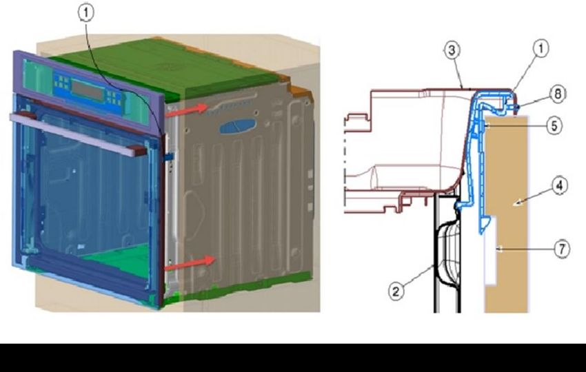
Embodiment 2
As shown in figs. 3 and 4, the other embodiment of the installation process of the invention indicates
how the oven is installed into the furniture (4). In comparison with embodiment 1, the difference is
that embodiment 2 discloses that the hole (7) size of the sidewall (2) is deeper in-depth and wider in
width. If a user directly pushes the oven into the furniture (4) during an installation process, an
engagement structure formed by the clip (4) and the hole (1) may be unstable and easily released.
In order to form a steady installation of the oven and the furniture (4), a distance clip (6) for fitting
and engaging with the clip (1) is prefixed on the hole (7). Therefore, the oven and the furniture (4)
still have a steady engagement structure by snapping the clip in the distance clip (6).
Accordingly, the invention provides an engagement structure between an appliance and a furniture
to reduce the installing time, provide a simplified installation without extra tools, and avoid the walls
of the furniture from occurring structure damages during the installation.
Page 3 of 5 Wednesday, October 28, 2020 Disclosure ID: 05343
Published by Technical Disclosure Commons, 2021 4Defensive Publications Series, Art. 4090 [2021]
Figure 1 showing an illustration of an installation process for an oven and a furniture according to
embodiment 1 of the invention.
Figure 2 showing an illustration of an engagement structure of a clip and a hole according to
embodiment 1 of the invention.
Figure 3 showing an illustration of an installation process for an oven and a furniture according to
embodiment 2 of the invention.
Figure 4 showing an illustration of an engagement structure of a clip and a hole according to
embodiment 2 of the invention.
List of components:
1. Clip 5. Ribs
2. Sidewall 6. Distance clip
3. Front frame 7. Hole
4. Furniture 8. Hook portion
Page 4 of 5 Wednesday, October 28, 2020 Disclosure ID: 05343
https://www.tdcommons.org/dpubs_series/4090 5Mohr: Hidden and tool-free installation of an appliance in the furnitur
8. Machine translations
German, French, Chinese,
Page 5 of 5 Wednesday, October 28, 2020 Disclosure ID: 05343
Published by Technical Disclosure Commons, 2021 6You can also read