Tate Grid User Installation Reference Guide
←
→
Page content transcription
If your browser does not render page correctly, please read the page content below

Structural Ceiling

Tate Grid User Installation
Reference Guide

          THIS INFORMATION MUST BE SHARED WITH ALL SERVICE PROVIDERS
           WHO INTEND TO SUSPEND SERVICES FROM THE TATE GRID SYSTEM

         NOTE: MAX. TORQUE OF 30 IN-LBS FOR ALL CONNECTIONS TO GRID

           7510 Montevideo Road, Jessup, MD 20794 • T:410-799-4200 • E: info@tateinc.com • W: tateinc.com   REV: 03/2022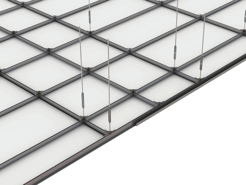
Structural Ceiling
Tate Grid User Installation Reference Guide

         THIS INFORMATION MUST BE SHARED WITH ALL SERVICE PROVIDERS
         WHO INTEND TO SUSPEND SERVICES FROM THE TATE GRID SYSTEM

Introduction
Thank you for choosing Tate Grid. The purpose of this guide is to provide you with a reference
for typical installation situations. We would be interested in hearing any comments you have
on this installation manual, product, or overall experience. Please call or email Technical Ser-
vices: Phone: 410-799-4200, Email: TateInfo@tateinc.com

Safety                                                                 Suitable Connection Methodology
Tate Grid is a structural ceiling system designed
to support static vertical loads. When installing
services to the bottom 3/8”-16 threaded channel,
the following instructions must be adhered to:

1. Do not torque the threaded rod or bolts above 30                                        Tate Grid
   in-lb. Over torquing will damage the threads of the
   slot reducing the load capacity of the Tate Grid
   system
                                                                             1.5” x 1.5” x 3/8”
2. There must be at least 0.6” thread engagement                             Square Washer
   between threaded rod or bolt
3. Be sure all bolts, nuts, and threaded rods are                                    3/8”-16 Hex Nut,
   properly tightened down as described in this guide.                               30 In-lbs tourque
4. Do not impose a dynamic load on the connection to
   Tate Grid. During installation of supported services,
   bracing is required to prevent dynamic load on the
                                                                             3/8”-16 Threaded HDG Rod,
   Tate Grid ceiling                                                         Hand Driven to Stop Point
5. All bottom thread fixings should be completed with
   suitable washers.
6. Do not put a load on the system until the
   installation is complete
7. Tate Grid is NOT a walk-on ceiling
8. 2 or more people are required for handling some of
   the pieces for this system
9. Wear personal protective equipment (PPE) when
   drilling, cutting, or installing. PPE includes gloves,
   safety eyeglasses, hard hats, etc.

                    7510 Montevideo Road, Jessup, MD 20794 • T:410-799-4200 • E: info@tateinc.com • W: tateinc.com   REV: 03/2022
1. Building Connections
Tate Scope of Supply:
Tate supplies Grid components up to the turnbuckle (A), suitable drop rod and building con-
nections (B) must be sourced by others.

                              B

        A

                                                                          Tate Grid hanging              Tate Grid hanging
                                                                          method from steel              method from concrete
                                                                          building                       building

The Tate Grid system may be hung either directly from structural steel or the above concrete slab.

                                                                   Drop Rod Frequency:

                                                                   Tate Grid requires connections every 4’ x 4’
                                                                   on center, and always along the perimeter.

                7510 Montevideo Road, Jessup, MD 20794 • T:410-799-4200 • E: info@tateinc.com • W: tateinc.com      REV: 03/2022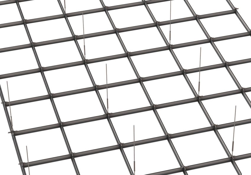
Structural Ceiling
Tate Grid User Installation Reference Guide

2. General Layout & Part Numbers

Joints of Main Runners                    Turnbuckle Drops mid-Main Runner                     Structural Tee Connections
Turnbuckle & Starter Rod (PN28361)        Turnbuckle & Starter Rod (PN28361)                   Field Connector (PN22293)
XL Connector (PN22297)                    Field Connector (PN22293)                            1/4”-20 Screw (PN23077)
1/4”-20 Screw (PN23077)                   1/4”-20 Screw (PN23077)                              1/4” Lock Washer (PN23078)
1/4” Lock Washer (PN23078)                1/4” Lock Washer (PN23078)

                   7510 Montevideo Road, Jessup, MD 20794 • T:410-799-4200 • E: info@tateinc.com • W: tateinc.com   REV: 03/2022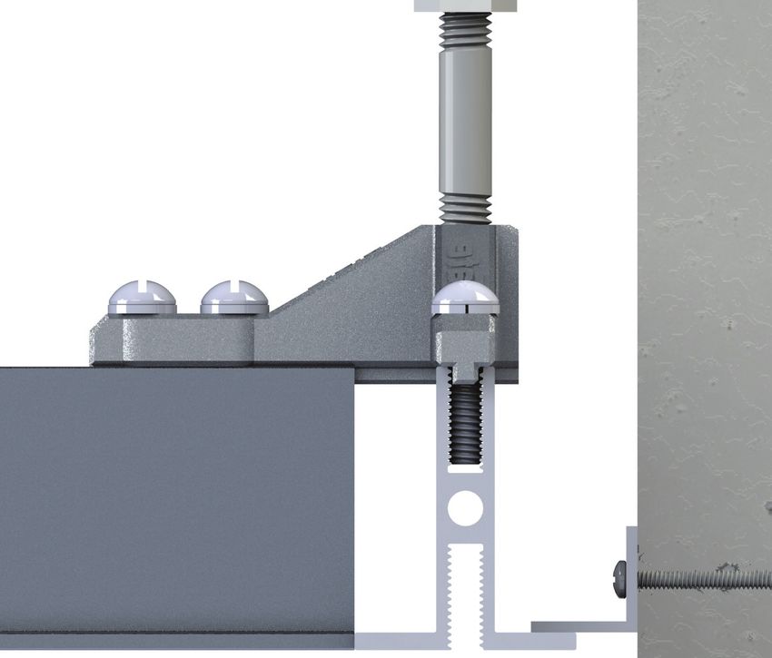
Perimeter Intersection                                       Perimeter & Structural Tee/MR Intersection
Perimeter Connector (PN22295, 2 legs removed                 Perimeter Connector (PN22295, 1 leg removed
in field)                                                    in field)
1/4”-20 Screw (PN23077)                                      1/4”-20 Screw (PN23077)
1/4” Lock Washer (PN23078)                                   1/4” Lock Washer (PN23078)

          7510 Montevideo Road, Jessup, MD 20794 • T:410-799-4200 • E: info@tateinc.com • W: tateinc.com   REV: 03/2022
Structural Ceiling
 Tate Grid User Installation Reference Guide

 3. Connector Details
 Tate Grid Connector Types
 Note: Every connection can be anchored using a starter rod and turnbuckle.

            Field Connector                              XL Connector                                   Perimeter Connector
                                                       Main Runner Splice                             Easily cut for along walls

 Field Connector Detail

Structural Tee coped for easy
installation and stronger connections

                                                                                                     Ribs on connector to align with
Main Runners notched to positively position
                                                                                                     grid and prevent racking
connectors on center every time

                      7510 Montevideo Road, Jessup, MD 20794 • T:410-799-4200 • E: info@tateinc.com • W: tateinc.com         REV: 03/2022
XL Connector and Splice Pin Detail (Main Runner Splice)
The XL Connector is designed for additional support at the end of each Main Runner. The end
of each Main Runner also has a Splice Pin inserted in the factory. The other end of the pin
should be inserted into the next Main Runner

  Factory Installed
     Splice Pin

                           Main Runner Notch

Perimeter Connector Detail

                                       Bottom of Perimeter                                                         Perimeter Connector
                                       Connector is designed                                                       can be cut on site
                                       with ribs that locate                                                       to be used in various
                                       the connector on                                                            locations to connect
                                       Perimeter Extrusion.                                                        grid together.

                      7510 Montevideo Road, Jessup, MD 20794 • T:410-799-4200 • E: info@tateinc.com • W: tateinc.com         REV: 03/2022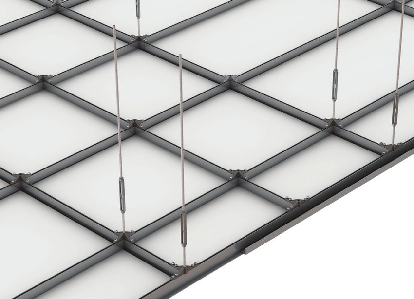
Structural Ceiling
Tate Grid User Installation Reference Guide

4. Notch Details
Structural Tee & Main Runner Notches
The main runners are not symmetric, they
must all be oriented in the same direction. Be
sure that all runs of main runners are oriented
in the same direction or the grid will not align
properly.

All Structural Tees and Main Runners are
notched every 24” on center for proper align-
ment and spacing of the connectors.

For 2’x2’ grid systems, the 4’ tees should first be
installed between the main runners and orient-
ed such that the witness notches at the ends
of the 4’ tees are all oriented in the same direc-
tion. This will ensure that the 2’ tees will align
properly and parallel to the mains.

                 24” nominal
                                                                24” & 48” Structural Tees have coped ends which allow the grid to rest on the
                                                                longer sections for stronger connections.

                                                                48” Structural Tees and 12’ Main Runners are notched every 24” on center for
                 24” nominal         24” nominal                proper alignment and spacing of the connectors.

                                                                                        24”                     24”

                                                                       144”

              Note: Structural Tee and Main Runner dimensions are nominal and are adjusted for custom-sized ceiling grid designs

                    7510 Montevideo Road, Jessup, MD 20794 • T:410-799-4200 • E: info@tateinc.com • W: tateinc.com                   REV: 03/2022
5. Perimeter Details
Perimeter Options:
The Tate profile should run along all perimeters and should be anchored every 4’. This serves
multiple purposes:
   • An engineering purpose as it ensures no part of the system is cantilevered.
   • An installation purpose as the notches every 24” on the profile help you set out during
      installation.
   • It also has aesthetic and air sealing benefits as the tiles sit better in this design.

If this design is not followed, the members of Tate Grid terminating at the wall may
not be structurally sound and may deflect and fail under load.

There are two options when installing Tate Grid at the perimeter of a data hall: Floating and
Fixed. Floating perimeters utilize standard Main Runner components which can also be used
in other areas of the data hall. Fixed Perimeter details utilize special 12’ Fixed Perimeter Angles
and typically don’t require hangers in the case where the connection to the wall is engineered
for the purpose of carrying the rated capacity of the grid.

XL Connector (Field-Cut)                                              Perimeter Connector
for Floating Installation

 Main Runner
                                                                        Perimeter Extrusion

               Wall Angle

   Floating Installation Detail                                    Fixed Installation Detail
   Main Runners are utilized when installing with a                Perimeter Extrusions are designed to create a clean
   floating detail. When installing with a floating                corner joint assembly. Perimeter Angles can be cut
   perimeter, XL Connectors can be utilized to take                on site to desired length when assembled along
   advantage of the notches and ribs that align                    perimeter walls. Perimeter Angles can be bolted to
   extrusions and prevent racking.                                 the wall with appropriate fasteners for the wall type.

   Additionally it is recommended to utilize a Wall                Note, pre-drilling is recommended and through holes
   Angle attached to the perimeter.                                are suggested for simpler light fixture or drop ceiling
                                                                   tile installation.
                  7510 Montevideo Road, Jessup, MD 20794 • T:410-799-4200 • E: info@tateinc.com • W: tateinc.com   REV: 03/2022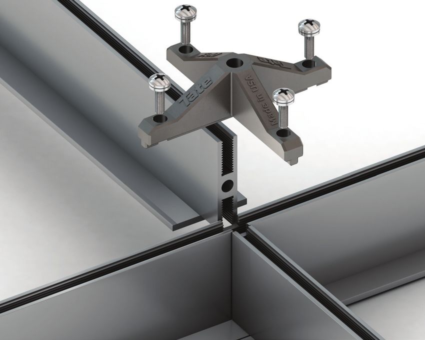
Structural Ceiling
Tate Grid User Installation Reference Guide

5. Perimeter Details
Standard Floating Perimeter Detail

                                                              XL Connector

                                                                        Drop Rod
                                                                        (by others)

              Turnbuckle                                                                                            Floating
              Assembly                                                                                              Perimeter

              Field                                                                             Wall Angle
              Connector
                                                                         Perimeter
                                                                         Connector

              Main Runner/
              Cross Tee

                   7510 Montevideo Road, Jessup, MD 20794 • T:410-799-4200 • E: info@tateinc.com • W: tateinc.com       REV: 03/2022
6. Ceiling Assembly
Bolt Torque
All bolt connections to the top slot of the grid should be tightened flush to a washer with a
maximum torque value of 30 in-lb, using a torque limiting screw gun or ratchet similar to:
All bolt or nut connections to the bottom slot of the grid should be tightened flush to a washer
or mounting bracket with a maximum torque value of 30 in-lb, using a torque limiting screw
gun or wrench similar to:
Thread Engagement
When threading bolts or threaded rod into bottom slot to hang equipment, ensure that the
bolt or rod is long enough to fully engage the depth of the slot entirely or thread tear-out could
be possible. Any less than 75% (0.6”) engagement could cause thread tear-out at less than
rated loads for the system.
7510 Montevideo Road, Jessup, MD 20794 • T:410-799-4200 • E: info@tateinc.com • W: tateinc.com REV: 03/2022Structural Ceiling
Tate Grid User Installation Reference Guide
Field Grid Assembly
While Tate Grid can be customized to meet the needs of your specific application, the following
example is based on 2’ x 2’ grid spacing with turnbuckle connections on 4’ x 4’ centers.
Step 1
Install Main Runners
The Mains are equally spaced every 4’. All
thread and turnbuckles are placed every
4’ along the mains to connect them to
the building structure. Field Connectors
are used along the Mains and the
connection point between two adjoining
Mains require XL Connectors.
Step 2
Install 4’ Structural Tees
The Structural Tees are placed every 2’
along the Mains. The 4’ Tee’s are factory
coped on each end so that they rest on
top of the Mains. All connections are
aligned using factory cut notches every 2’
in the top edge of the Mains. The notches
along the Mains provide proper location
and alignment of the grid and speed up
installation.
Step 3
Install 2’ Structural Tees
For ceilings planning to use a 2’ grid,
additional 2’ Structural Tees can be
installed between the 4’ Structural Tees.
These 2’ Structural Tees connect to the
4’ Tees using Field Connectors. The
connectors are aligned using factory
cut notches in the top edge of the 4’
Structural Tee.
7510 Montevideo Road, Jessup, MD 20794 • T:410-799-4200 • E: info@tateinc.com • W: tateinc.com REV: 03/20227. Service Conditions
Connecting to the bottom slot of the Grid:
A standard 3/8”-16 threaded rod can be used to suspend services from the 3/8”-16 bottom
slot of the Grid. Fixings to the bottom slot of the Grid must be at least 75% engaged, or to a
depth of at least 0.6”.
Bottom Slot Torque:
30 in-lb max, See Section 6 for details
Hot Aisle Containment:
Hot Aisle Containment components supplied by Tate can
easily be secured to the bottom slot of the Grid.
Performance Criteria
The following load capacities must be strictly observed when installing services from the
Tate Grid.
48”
24”
Load
Load Load
Grid Load Performance Connection to Bottom Slot Connector in line with
Hanging Method (with building connections 4’x4’ on centers) (1/4”-20, 3/8”-16 or M10-1.5mm) building connection
Safety Factor 2x 4x 2x 4x 2x 4x
Point Load (lbs) 380 lbs* (1.7 kN) 190 lbs* (.85 kN) 380 lbs* (1.7 kN) 190 lbs* (.85 kN) 800 lbs (3.6 kN) 400 lbs (1.8 kN)
Uniform Load (lbs/ft2) 50 lbs/ft2 (2.4 kN/m2) 25 lbs/ft2 (1.2 kN/m2) – - –
Ultimate Point Load (lbs) 700 lbs (3.1 kN) 350 lbs (1.6 kN) 760 lbs (3.4 kN) 380 lbs (1.7 kN) 1600 lbs (7.1 kN) 800 lbs (3.6 kN)
*Max point load no less than 4’ (120 cm) apart in any direction.
7510 Montevideo Road, Jessup, MD 20794 • T:410-799-4200 • E: info@tateinc.com • W: tateinc.com REV: 03/2022Structural Ceiling
Tate Grid User Installation Reference Guide
Field System Performance:
The Ultimate Load of the Tate Grid system is the point at which the system will fail - see stress
graph below:
Structural Tee Deflection
(Midspan Beam)
48”
24”
Load
Ultimate Load = 700 lbs
Calculate midspan beam deflection at any point below yield
Wl3 S = Deflection E = 10x106 lbs/in2
Deflection (in)
S= W = load I = .153 in4
48EI l = 48in
1.00
Yield Point = 380 lbs
0.75
0.50
0.25
Cable Installation & Bracing Drops:
Do not pull cables or expose the 100
Grid to
300any
500dynamic
700 900loading. Dynamic loads and dragging
cables across the Grid may exceed the Ultimate Load of the Grid.
To distribute a load that would otherwise exceed the
stated 380 lb point load, cable ladders can be employed to
achieve up to 50 psf. The example to the right shows the
recommended method to distribute load so as to ensure no
single 3/8” stud exceeds the 380 lb point load.
Please note: Bracing is required during cable pull.
The installer should use a bracing method to hold the
ladder racks in position so when cables are pulled
during install the ladder does not swing back or
forth. Bracing must be strictly adhered to to avoid
exceeding the stated system load tolerances.
7510 Montevideo Road, Jessup, MD 20794 • T:410-799-4200 • E: info@tateinc.com • W: tateinc.com REV: 03/20228. Maintenance
Cleaning:
To clean Tate Grid components please use a common non-abrasive mild detergent contain-
ing less than 0.5% phosphate and water, applied using a sponge. The components should be
dried using a soft towel. If solvents are required to remove materials not soluble in water such
as petroleum products, the following solvents can be used: Isopropyl alcohol, denatured alco-
hol, mineral spirits or methanol. Paint scratches can be touched up. Contact the factory for
matching paint.
Maintenance of above ceiling services:
The Tate Grid system should not be walked on under any circumstances. This may expose the
system to excess dynamic loads and cause a failure.
Ceiling tiles may be removed to build a scaffold like structure that rises through the Grid and
can allow walk-on access above the Grid without exposing the Grid system to extra loads.
7510 Montevideo Road, Jessup, MD 20794 • T:410-799-4200 • E: info@tateinc.com • W: tateinc.com REV: 03/2022Corporate Headquarters: Asia Sales & Support Office:
7510 Montevideo Road, 1 Commonwealth
Jessup, MD 20794 #07-26 One Commonwealth,
Tate Hotline: 1-800-231-7788 Singapore 149544
Tel: +1 410 799 4200 Tel: +65 6264 5942
Fax: +1 410 799 4207
Australian Sales & Support Office:
Production Facilities:
3 Herbert Place, Smithfield NSW 2164,
7510 Montevideo Road, Sydney, Australia
Jessup, MD 20794 Tel: +61 2 9612 2300
Fax: +61 2 9612 2301
52 Springvale Road,
Red Lion, PA 17356
Tel: +1 717 244 4071
Fax: +1 717 246 3437 European Sales & Support:
EDI House, Kylemore Park West,
Ballyfermot,
Dublin 10, D10 KH30 Ireland
Canadian Sales & Support Office:
Tel: +353 (1) 685 6518
880 Equestrian Court,
Oakville, ON L6L 6L7 Canada
Tate Hotline: 1-800-231-7788
Tel: +1 905 847 0138 Middle East Sales & Support:
Fax: +1 905 847 0141
Jebel Ali-Lahbab Road (E 77 Road),
Dubai Investment Park,
United Arab Emirates
Tel: +971 56 199 8368
Central and South American
Sales & Support:
Tel: +1 954 412 2334
A Kingspan Group
Company
Tate components
are proudly made
in the U.S.A.
Tate reserves the right to amend product information without prior notice. Care has been taken
to ensure that the contents of this publication are accurate, but Tate, its parent company and its
subsidiary companies do not accept responsibility for errors or for information that is found to be
misleading or outdated. Suggestions for, or description of, technical specifications and the end use or
application of products are provided in good faith and should be verified prior to use.
To ensure you are viewing the most recent and accurate product information, please visit this link:
www.tateinc.com
2/2022 R:3/2022You can also read


