Stress corrosion cracking behavior of welding joint of high strength steel
←
→
Page content transcription
If your browser does not render page correctly, please read the page content below

IOP Conference Series: Materials Science and Engineering

PAPER • OPEN ACCESS

Stress corrosion cracking behavior of welding joint of high strength steel
To cite this article: R Sepe et al 2021 IOP Conf. Ser.: Mater. Sci. Eng. 1038 012055

View the article online for updates and enhancements.

                               This content was downloaded from IP address 46.4.80.155 on 23/09/2021 at 21:09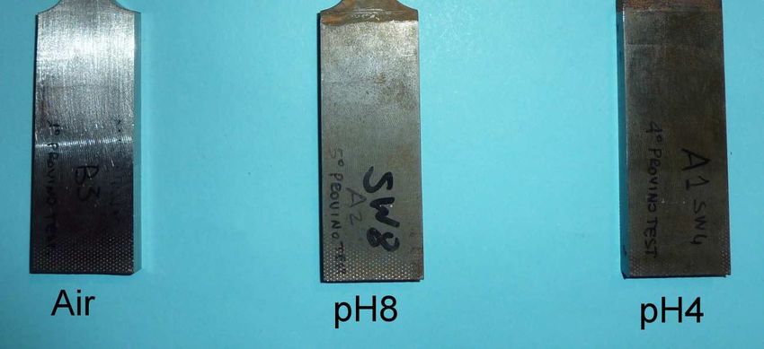
The 49th AIAS Conference (AIAS 2020)                                                                                     IOP Publishing
IOP Conf. Series: Materials Science and Engineering              1038 (2021) 012055           doi:10.1088/1757-899X/1038/1/012055

Stress corrosion cracking behavior of welding joint of high
strength steel

                     R Sepe1, F Bollino2, F Caiazzo1 and F Berto3
                     1
                       Dept. of Industrial Engineering, University of Salerno, Via Giovanni Paolo II, 132 -
                     84084 – Fisciano (SA) - Italy
                     2
                       Dept. of Engineering, University of Campania “Luigi Vanvitelli”, via Roma 29,
                     81031, Aversa (CE), Italy
                     3
                       Dept. of Mechanical and Industrial Engineering, Norwegian University of Science
                     and Technology, 7034 Trondheim, Norway

                     E-mail: rsepe@unisa.it

                     Abstract. Nowadays, high-strength steel structures are increasingly being used in marine or
                     soil environments, but low attention has been paid on the corrosion and stress corrosion
                     cracking problem. In this paper, the susceptibility to stress corrosion cracking (SCC) of butt-
                     welding joints of Strenx® 700 (S690QL high strength steel) both in marine and acid-polluted
                     marine atmospheres was studied, by using slow strain rate tensile (SSRT) test. The seawater
                     corrosion environment was considered and it was prepared following the ASTM D1141. To
                     study the influence of the environment pH, NaOH 0,1M solutions and pure H2SO4 were used to
                     adjust the pH of the simulated seawater solution to 8 and 4, respectively. The slow strain rate
                     tensile tests (SSRT) with a crosshead speed of 0.000017 mm/s were carried out at room
                     temperature (approximately 25 °C). After failure, the SCC susceptibility was evaluated
                     acquiring the elongation loss rate and the reduction-in-area loss rate. The fracture surfaces were
                     analyzed by SEM observation.

1. Introduction
Nowadays, although the introduction of advanced materials, the metals remain the materials of choice
in structures and machinery for their strength, stiffness, toughness, and resistance to high
temperatures.
    However, most metals are susceptible to corrosion phenomena. The corrosion can occur in several
forms. When it takes place in conjunction with mechanical stress can lead to a failure by cracking,
which is named stress corrosion cracking (SCC). This event was responsible for several disasters
which caused significant economic losses throughout the world, such as the rupture of high-pressure
gas transmission pipes, the explosion of boilers, and the destruction of power stations and oil
refineries. The onset of such catastrophic failures generally occurred without any prior warning [1, 2].
SCC, indeed, can cause high and fast loss of mechanical strength with little metal loss causing the
fracture and, thus, the failure of components and structures. Fortunately, the development of such
cracks on a structure is relatively rare, because requires the simultaneous achievement of three
conditions: a specific corrosive environment able to promote the crack formation, metallurgic features
of the material making it susceptible to SCC, and tensile stress higher than a specific threshold value
inducing SCC [1]. The SCC failure can take place at a stress intensity factor below the fracture
toughness, KIC, and stress below the yield stress [3].

              Content from this work may be used under the terms of the Creative Commons Attribution 3.0 licence. Any further distribution
              of this work must maintain attribution to the author(s) and the title of the work, journal citation and DOI.
Published under licence by IOP Publishing Ltd                          1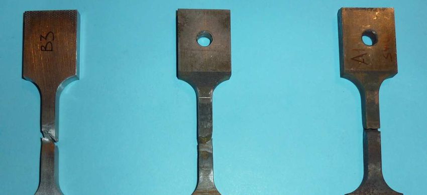
The 49th AIAS Conference (AIAS 2020)                                                               IOP Publishing
IOP Conf. Series: Materials Science and Engineering     1038 (2021) 012055    doi:10.1088/1757-899X/1038/1/012055

   The need for avoiding catastrophic failures of structures and machinery due to SCC has induced
many research groups to address their efforts towards the study of the mechanisms driving the
phenomenon and the identification of the factors that affect it as well as the strategies for its hindering.
   High-strength steels (HSSs) are highly susceptible to SCC. The process involves electrochemical
reactions that take place at the crack tip. In the aqueous environment, the most likely reactions
occurring are the following [3]:
                                             Anodic reaction:       M → Mn+ + ne-                            (1)
                                  Cathodic reactions: O2 + 2H2O + 4e- → 4OH-                                 (2)
                                                        +       -
                                                      2H + 2e → H2                                           (3)
    The electrochemical conditions at the crack tip (e.g. elettrochimical potential, pH, oxygen
concentration, etc.) favour one of the two cathodic reactions, determining the mechanism leading to
the onset of the SCC. To date, two main mechanisms have been identified: The anodic dissolution
(AD) and the hydrogen embrittlement (HE) [3]. The first is due to the occurring of the anodic reaction
at the grain boundaries.
    The AD can take place when the repeated rupture of the passive film covering the crack sides
occurs, leading to its advancement with a speed related to the metal dissolution rate at the crack tip [3].
This mechanism is favoured by a high pH, while a near-neutral or low pH values, together with a low
concentration of oxygen, induce the occurring of the second mechanism additionally to AD [4]. HE,
indeed, induces a failure due to the transport and location of the hydrogen produced by the cathodic
reaction (Equation (2)) into the material. This causes a reduction in ductility and strength of the alloy
and results in a nonductile fracture [3].
    In addition to the pH of the environment, the microstructure of the steel plays an important role in
the occurrence of the SCC [5, 6]. The literature, for example, proves that ferrite is the phase more
resistant to HE whereas the martensite and bainite are susceptible to HE [6, 7]. The dependence on
microstructure contributes to explain the high susceptibility of the welded joints of HSS to the SCC.
    The welding microstructure in the heat-affected zone (HAZ), indeed, is different from that one of
the base material. Generally, the HAZ has a complex microstructure where more phases (mainly
granular bainite, upper bainite, lath bainite, acicular ferrite, quasi-polygonal ferrite,
martensite/austenite) coexist and, thus, the welding can show a different SCC behaviour compared to
the structures [8]. The high susceptibility of the welding to the SCC is also due to the stress
concentration in such areas of the structure [8]. Therefore, when the external passivation coating of the
structure in the HSS is disbanded putting the material in contact with the corrosive environment, the
coupling with the tensile stress can engender SCC failure. The HSSs are widely used in structures such
as ocean engineering equipment (e.g. offshore platform, infrastructure construction in coastal regions,
etc.) or buried high-pressure and long-distance oil/gas transmission pipelines, where such materials are
exposed to aggressive environments, such as soils with several chemical compositions or the seawater,
that is one of the most corrosive environment due to the high chlorides concentration. Moreover,
welding is an essential process in the application of the materials for most structures. Therefore, the
SCC issue has high relevance.
    The present work aims to investigate the SCC behaviour of welded joints of S690QL HSS
subjected to the corrosion action of the marine atmosphere by conducting slow strain rate tensile
(SSRT) tests. Further, to study the effect of pH value on SCC behaviour of such materials, the tests
were carried out exposing the specimens to simulated seawater solutions prepared according to ASTM
D1141 and adjusting the pH to 8 (for simulating the marine environment) and 4 (for simulating an
acid-polluted marine atmosphere) with 0.1M solutions of NaOH and pure H2SO4 respectively.

2. Materials and methods

2.1 Specimens preparation
Strenx 700 of SSAB (S690Q) HSS was employed in the present study. The typical chemical
composition of the material used in the experimental tests and the mechanical properties at room

                                                            2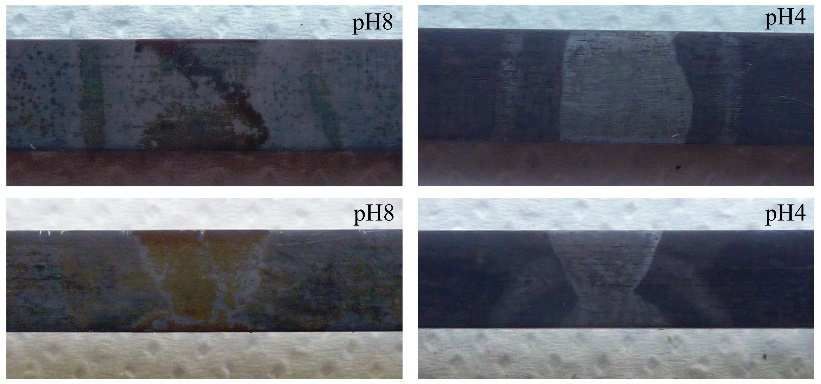
The 49th AIAS Conference (AIAS 2020)                                                                                         IOP Publishing
IOP Conf. Series: Materials Science and Engineering            1038 (2021) 012055                doi:10.1088/1757-899X/1038/1/012055

temperature are reported in Tables 1 and 2, respectively, where σs is yield stress, σu is tensile strength
and As is the elongation at break.

                     Table 1. Chemical composition (wt%) of the Strenx 700 of SSAB.
 C     Simax     Mnmax          Pmax         Smax         Crmax          Cumax        Nimax          Momax            Bmax         Ceq
 0.2       0.6      1.60         0.020          0.010          0.80          0.30           2.0           0.70           0.005      0.34

                    Table 2. Mechanical properties of the Strenx 700 of SSAB.

                            σs [MPa]                σu [MPa]                                     As [%]
                              700                   780÷930                                       14

  Two butt joints were made using 8 mm thick S690Q HSS plates by means Metal Inert Gas (MIG)
welding process. Two plates with sizes 150x100x8 mm×mm×mm were welded in double multipass
welding, with welding parameters reported in Table 3.

                                              Table 3. Welding parameters.

                   Pass                  Current               Voltage           Welding Speed              Wire diameter
                                          [A]                   [V]                 [mm/s]                     [mm]
                    1                     192                   19.3                     2.32                      1.2
                    2                     180                   19.4                       2.5                     1.2

   Both weld passes have been carried out at uniform speed and under room conditions, using a 1.2
mm diameter metal-cored wire LNM MoNiVa Lincoln Electric (AWS A5.28 ER110S-G). The typical
chemical composition and mechanical properties of the filler material are reported in Table 4.

                    Table 4. (a) Chemical composition (wt%) and (b) mechanical
                    properties of filler material.
                    (a)
                        C           Si      Mn          Cr            Cu            Ni              Mo            V
                     0.08        0.44       1.7         0.23          0.25          1.35            0.3          0.08

                    (b)
                               σs [MPa]                        σu [MPa]                             As [%]
                                 710                              790                                  20

   After that, the welding joints were milled on opposite side and their thickness was reduced to 5.6
mm to obtain specimens with a uniform cross-section. According to ASTM E8, specimens with the
shape showed in figure 1, were obtained. Afterword, the tensile specimens were cut out from butt
joints for direct tensile test. Three specimens were tested for each environment evaluated.

                                                                  3
The 49th AIAS Conference (AIAS 2020) IOP Publishing
IOP Conf. Series: Materials Science and Engineering 1038 (2021) 012055 doi:10.1088/1757-899X/1038/1/012055
Figure 1. Shape and size of the tested specimens, according to ASTM E8.
2.2 Corrosive environment
Before the tensile tests, the specimens were immersed in solutions simulating the seawater for 7 days.
The artificial seawater was prepared according to ASTM D1141-98 standard to obtain the chemical
composition reported in Table 4. All used reagents were provided by Sigma Aldrich (Milan, Italy).
Table 5. Chemical composition (g/L) of the artificial seawater testing solution, according to ASTM
D1141-98 standard.
NaCl MgCl2·6H2O Na2SO4·H2O CaCl2·6H2O KCl NaHCO3 KBr
24.5300 5.2000 4.6087 2.2898 0.6950 0.2010 0.1010
The suitable amount of each salt was weighed with an analytical balance (KERN, ABJ 120-4NM)
and solubilized in deionized water under magnetic stirring. Afterwards, the solution was brought the
final volume with the addition of water within a volumetric flask. Moreover, the pH value of the
solution was adjusted to 8 and 4 by adding some drops of 0.1 M NaOH solution and pure H2SO4
(95÷97%) respectively.
2.3 SSRT Testing
To investigate the SCC susceptibilities of HSS steel, slow strain rate tensile test (SSRT) with a
crosshead speed of 0.000017 mm/s was conducted with Zwick Roell testing machine equipped with a
load cell of 250 kN. The gauge section of each specimen, with the dimension of 32x6x5.6
mm×mm×mm, was ground sequentially to 1500 grit with the last grinding along the axial direction.
Then the specimens were cleaned with acetone and dried in air. An extensometer with a length gage of
25 mm was used. The SCC susceptibility was evaluated acquiring the elongation loss rate (Iδ) and the
reduction-in-area loss rate (Iψ) by the following formulas:
δ
Iδ = 1- δ s x 100 (4)
0
Iψ = 1- ψs x 100,
ψ
(5)
0
where: δ0 and ψ0 are the elongation and area reduction of specimens in air environment, while δs and
ψs are the elongation and area reduction of specimens in the corrosion solutions respectively.
3. Results and discussion
The exposure to corrosive artificial seawater for 7 days led the formation of a precipitate on the
surface of all specimens. Its typical orange-brown colour allows to identify it as rust (Fe2O3·nH2O)
formed starting from the products of the anodic reaction (equation (1)) and the cathodic reaction
reported in the equation (2). The amount of precipitate is greater on the surface of the specimens
exposed to alkali environment. In acid solution, indeed, the reduction of the oxygen molecules
4The 49th AIAS Conference (AIAS 2020) IOP Publishing
IOP Conf. Series: Materials Science and Engineering 1038 (2021) 012055 doi:10.1088/1757-899X/1038/1/012055
(equation (2)) competes with the reduction of the hydrogen ions (equation (3)) which leads to
hydrogen molecules formation. Therefore, a lower amount of products are available for rust formation.
After soaking, all samples were washed with deionized water and dried, before to perform the
tensile tests. In Figure 2, some photographs of the cleaned specimens after soaking in the seawater
solutions, and in particular an enlargement view of the welding joints, are reported.
Figure 2. Photographs of specimens after 7 days of soaking in
artificial seawater (enlargement on welding).
To evaluate the susceptibilities of HSS steel to the SCC, SSRT tests were carried out. Figure 3
shows the photographs of the specimens after the tests. In Table 6 the elongation loss rate (Iδ) and the
reduction-in-area loss rate (Iψ) are reported. The maximum strength value was for all tests was about
700 ± 10 MPa. Data analysis shows that the SCC susceptibility of (S690Q) steel is higher in acid
artificial seawater (pH = 4). This can be due to synergic effect of anodic dissolution (AD), due to the
oxidation of the metal atoms (equation (1)), and hydrogen embrittlement (HE), caused by the
hydrogen molecules formed in the acid environment by the hydrogen ions reduction (equation (3)).
Table 6. SSRT tests results.
Corrosion environment A[%] Iδ [%] Iψ [%]
Air 7.03 -- --
pH 8 seawater 6.25 11.11 2.24
pH 4 seawater 5.47 22.22 92.14
Figure 3. Specimens after SSRT tests.
5The 49th AIAS Conference (AIAS 2020) IOP Publishing
IOP Conf. Series: Materials Science and Engineering 1038 (2021) 012055 doi:10.1088/1757-899X/1038/1/012055
In figure 4 are shown the fracture surfaces
surface obtained by SEM observation. As it is possible to
observe the fracture surfaces are different and depend on corrosion environment.
a) b) c)
d) e) f)
Figure 4. Surfaces of fracture of specimens subjected to different corrosion environments: (a) and (d)
air, (b) and (e) pH 8 seawater, (c) and (f) pH 4 seawater.
4. Conclusions
In the present work, stress corrosion cracking behaviour
behavio r of (S690Q) steel in artificial seawater with
different pH are investigated. The results showed that (S690Q) steel is more susceptible to SCC in
acid artificial seawater (pH=4) probably because in such environmental conditions both the anodic
dissolution (AD) and hydrogen embrittlement (HE)
( mechanisms drive the failure event.
event
Acknowledgements
This work was supported by the Programma VAnviteLli. pEr la RicErca -V:ALERE
V:ALERE 2017.
2017
5. References
[1] Koch G H 2001 Adv Mater Process 159(8) 36 - 8.
[2] International A. ASTM D1141-98,
D1141 Standard Practice for the Preparation of Substitute Ocean
Water. West Conshohocken, PA2013.
[3] Ramamurthy SandAtrens A 2013 Corros Rev 31(1) 1.
[4] Liu Z Y, Li X G, Du C W, Zhai G LandCheng Y F 2008 Corros Sci 50(8) 2251-7.
2251
[5] Liu Z Y, Li Q, Cui Z Y, Wu W, Li Z, Du C WandLi X G 2017 Constr Building Mater 148 131-9.
[6] Ma H, Liu Z, Du C, Wang H, Li CandLi X 2015 Mate Sci Eng A 642 22-31. 31.
[7] Park G T, Koh S U, Jung H GandKim K Y 2008 Corros Sci 50(7) 1865-71. 71.
[8] Li X, Liu J, Sunn J, Lin X, Li CandCao N 2019 Corros Sci 160 108167.
6You can also read