Securing Greater Safety - A variety of functions for enhanced safety and mounting efficiency - Omron Europe
←
→
Page content transcription
If your browser does not render page correctly, please read the page content below
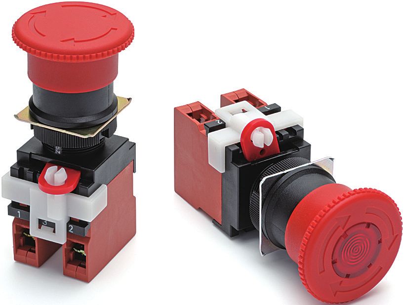
Emergency Stop Pushbutton Switches
A22NE-PD/A22NE-P/A22E Series

                                                     Securing Greater
                                                               Safety
                                                                                     A variety of functions for
                                                  enhanced safety and mounting efficiency

                                                                               NEW
            Basic:                     Vibration-resistant:          Push-In Plus Terminal Block +
   Screw Terminal Block Types   Push-In Plus Terminal Block Types   Lock-lever-linked Contact Types
        A22E Series                  A22NE-P Series                     A22NE-PD Series
2 | Emergency Stop Pushbutton Switches A22NE-PD/A22NE-P/A22E Series

  Machines Are
  Designed to Stop
  Without Fail.
  An emergency stop pushbutton switch stops machine equipment
  in an emergency to protect the safety of workers.
  However, if the switch does not function properly due to human error,
  malfunction, defective wiring or other reasons, it will lead to a major accident.
  That is why Omron has focused on stopping machines without fail
  and produced a lineup of emergency stop switches with enhanced functionality.

| 3

   Three Functions to Enhance Reliability
                      Stops machines when a Switch is
                      improperly mounted.
                     ・Cuts off the current when the lock lever is off.                                                       STO
                                                                                                                             STOP
                     ・Instantly detects work errors and lever damage.

Lock-lever-linked
   Contacts                        Refer to page       4 for details.

                      Reduces loose and detached wiring.
                     ・Wires are resistant to vibration and do not come off easily.
                     ・Reduces work for wiring and maintenance.

 Push-In Plus
Terminal Block                     Refer to page       5 for details.

                      Stable operation in harsh environments.
                     ・Usable up to 80℃ and pressures of 80 to 100 BAR.
                     ・Spray-resistant on the front and sides.

   Optional
    IP69K                          Refer to page       5 for details.

A Lineup That Allows You to Choose According to Your Needs

   Fully-loaded with Three Functions    Easy and Reliable Push-In Plus Terminal Block      Basic Screw Terminal Block

A22NE-PD            Series    Page 7    A22NE-P           Series          Page 21       A22E   Series              Page 37
4 | Emergency Stop Pushbutton Switches A22NE-PD/A22NE-P/A22E Series

Accident Prevention/Stable Operation

Suppress Malfunctions Throughly with Functions
for Various Applications.

                   Lock-lever-linked Contacts
                                                                                                                                                  Operation unit

                                 A22NE-PD Series

                                                                                                                                                  Lock lever
                                                                                                                                                  (ON state)

  Detects Improper Installations for Zero                                                                                                         Switch unit

  Malfunction Problems During Emergencies
  If the sliding operation of the lock lever is insufficient, the operation unit may not function properly when needed, even if
  pushed. With the lock-lever-linked contact function, if the sliding operation of the lock lever is insufficient, the original NC
  contact will turn to a NO state when the operation unit is not pushed, making it possible to detect errors from the state of
  the contact.

                     Lock lever         OFF                                                                    Lock lever          ON

                                     Current is cutoff.                                                                         Current flows.

                                                       Machine                                                                                  Machine
     The contact* opens and the current               equipment                          The contact* closes and the current                   equipment
     is cutoff.                                         stops.                           flows.                                                 operates.

                      * The example shows an NC contact. However, all contacts are interlocked with the lock lever, and the statuses of NO contacts are also switched.

     For machine
     equipment that can
     cause major
     accidents
     Ensures additional safety for
     machine equipment that
     cannot afford a slight delay.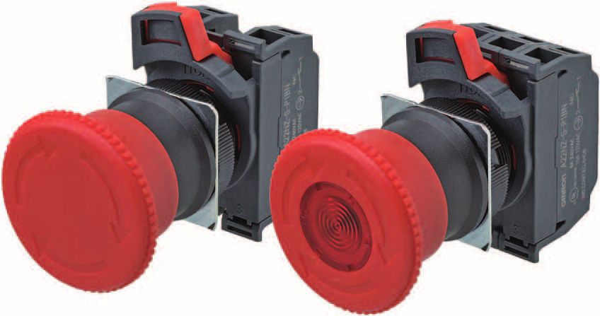
| 5

                 Push-In Plus Terminal Block
                     A22NE-PD/A22NE-P Series

Prevents Loose and Detached Wiring
Caused by Vibration During Operation
In addition to preventing unexpected stoppages caused by disconnection,
it is also possible to reduce maintenance efforts.

  Also help reduce                                                                           IEC standard Push-In Plus
                                                                                                           Terminal
                                                                                                                                       Screw
                                                                                                                                      Terminal
                                                                                                 (Cable
  the wiring work                                                                              diameter)    Block                      Block
                                                                                                20 N min
  Just insert wires like you would into                                                        (AWG20,             125 N               112 N
  an earphone jack. No tools are required.                                                      0.5 m㎡)
  They help reduce the time and work involved in wiring.             * Information for Push-In Plus Terminal Blocks and screw terminal blocks is
                                                                       based on OMRON's actual measurement value data for the XW2R.

                 Optional IP69K
                     A22NE-PD/A22NE-P Series

High-level Sealing that Is
Resistant to Harsh Environments
Conventional OMRON emergency stop
pushbutton switches were made to IP65
standards, but the unique technology used
for our rubber-designed covers achieves                  High temperature:80℃
                                                     High pressure:80 to 100 BAR
IP69K specifications that can withstand high-
temperature and high-pressure sprays from
any direction.

  For sites that demand
  high-level sanitation control
  Withstands high-temperature and high-pressure
  sprays without the need for an additional waterproof cover,
  allowing for worry-free installation in sites where cleaning
  with high-pressure washing machines is performed.
Emergency Stop Pushbutton Switches (22-dia. or 25-dia.)
                                     A22NE-PD/A22NE-P/A22E
A22NE-PD

                                    Install in 22-dia. or 25-dia.
                                    Panel Cutout (When Using a Ring)
                                    • Direct opening mechanism to open the circuit when the contact welds.
                                    • With a latching mechanism to prevent operating errors.
                                    • Lock lever for easily mounting and removing the Unit.
                                    • Use 25-dia. ring to install in 25-dia. panel cutouts. *
A22NE-P

                                    • In a model equipped with Lock-lever-linked contact function, the improper installation of the Switch Unit can be
                                      detected. (A22NE-PD)
                                    * Switches with an IP69K degree of protection do not support the 25-dia.

                                         Be sure to read the "Safety Precautions" on pages 18,
                                         33, 50, and 56.

                                                                                                 With Lock-lever-linked contact function
                                                                                                  A22NE-PD                     Page 7
A22E

                                       Push-in Plus
                                       Terminal Block Types
                                                                                                 Without Lock-lever-linked contact function
                                                                                                                                Page 21
                                                                                                 A22NE-P
 Common Accessories and Tools

                                                                                                 Without Lock-lever-linked contact function
Common Note

                                                                                                                                Page 37
                                                                                                  A22E
                                           Screw Terminal
                                           Block Types

                                6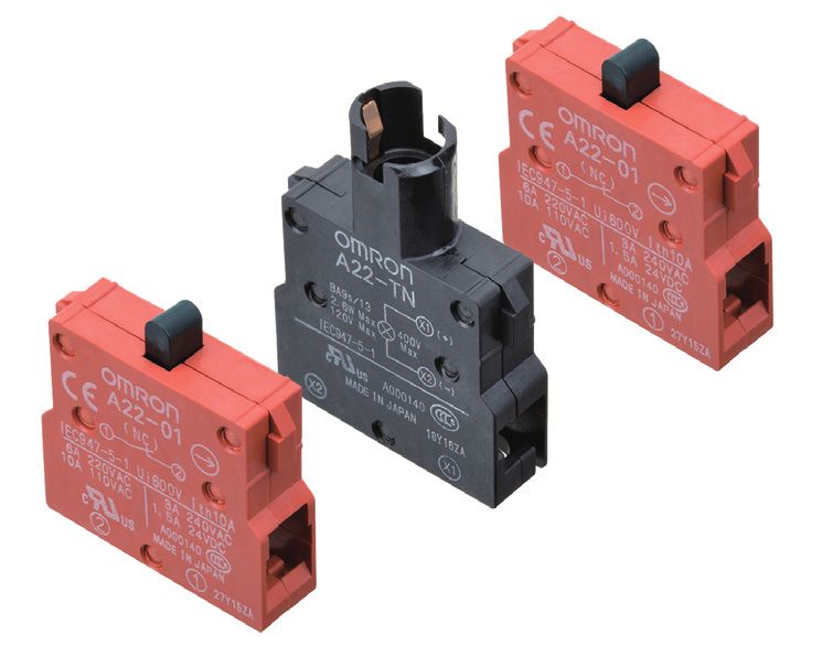
Emergency Stop Pushbutton Switches (22-dia. or 25-dia.) Push-in Plus Terminal Block Models
  With Lock-lever-linked Contact Function

  A22NE-PD

                                                                                                                                                              A22NE-PD
Install in 22-dia. or 25-dia. Panel Cutout
(When Using a Ring)
 • The small size of the control panel is realized by conserving
   space and changing the direction of the wiring.
 • Since there is no looseness in the wiring, there is a reduction in
   the maintenance efforts.
 • A maximum of up to four contact points can be combined
   together in the contact-point configuration.
 • Oil-resistant to IP65 (non-lighted models) / IP65 (lighted

                                                                                                                                                              A22NE-P
   models) / IP69K high-temperature, high-pressure cleaning
   (pull-reset models).                                                                        For the most recent information on models that have been
                                                                                               certified for safety standards, refer to your OMRON website.
 • Whether or not the Operation Unit and the Switch Unit have
   been properly mounted can be detected from the open/closed
   state of the contact (Lock-lever-linked contact function). *
  * All contacts are interlocked with the lock lever.
    (The statuses of both NC contacts and NO contacts are switched.)

         Be sure to read the "Safety Precautions" on pages 18 and 56.

Model Number Structure
Model Number Legend (Completely Assembled) ........ Shipped as a set which includes the Operation Unit, LED

                                                                                                                                                              A22E
                                                                                             Lamp (lighted models only), and Switch Block.
                                            1        2      3     4      5               6            7

                A22NE-                                   -P D                       -           -
1. Operation Unit size (diameter)
                                                                        5. Contacts
  Code            Description
    S                30 dia.                                                                  Number of                 Contacts
                                                                              Code
                                                                                              Contacts             NO               NC
    M                40 dia.

                                                                                                                                                               Common Accessories and Tools
    L                60 dia.                                                  01              one contact           0                1
                                                                              02             two contacts           0                2
                                                                              11                                    1                1
2. Reset function                                                             03             three contacts         0                3
  Code           Description                                                  21                                    2                1
  None             Turn-reset                                                 12                                    1                2
    P             Pull-reset *                                                22             four contacts          2                2

* The pull-reset type is only available on the 40 dia.                        13                                    1                3
  Operation Unit, non-lighted type.                                           04                                    0                4
  Not available on lighted types.
                                                                        Note. NO: 1a-contact NC: 1b-contact

3. Terminal specification
  Code               Description                                        6. LED lamp voltage
    P        Push-in plus terminal block                                      Code            Description
                                                                                                                                                              Common Note

                                                                                N              Non-lighted
                                                                                C             24 VAC/VDC
4. Lock lever function                                                  * Lighting color is red.
  Code                   Description
    D       Lock-lever-linked contact function
                                                                        7. Others (Degree of Protection)
                                                                               Code                                Description
                                                                               None           IP65
                                                                               69K            IP69K *
                                                                        * IP69K is supported only by the Pull-reset models.

                                                                                                                                                              7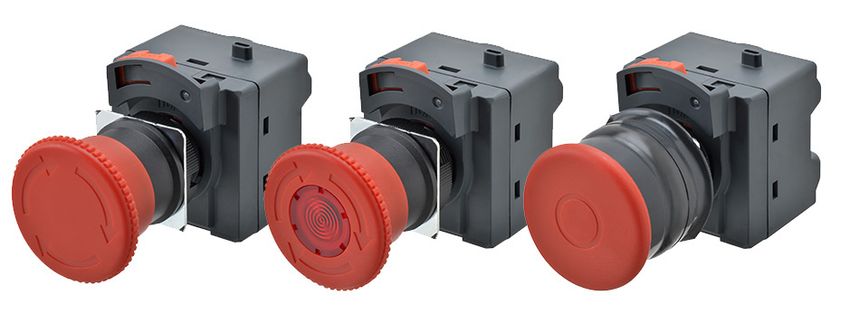
A22NE-PD
Ordering Information
A22NE-PD
List of Models (Completely Assembled)
Non-lighted Models (Without EMO/EMS Indication)
Appearance Operation Degree of Protection Contact configuration * Set Model Color of cap
2NC A22NE-MP-PD02-N
2NC, 1NO A22NE-MP-PD12-N
40-dia. head 3NC A22NE-MP-PD03-N
IP65 oil-resistant
Medium Pull-reset
models A22NE-MP-PD22-N
A22NE-MP-PD@@-N 2NC, 2NO
3NC, 1NO A22NE-MP-PD13-N
4NC A22NE-MP-PD04-N
2NC A22NE-MP-PD02-N-69K
2NC, 1NO A22NE-MP-PD12-N-69K
A22NE-P
40-dia. head 3NC A22NE-MP-PD03-N-69K
Medium Pull-reset IP69K
A22NE-MP-PD@@-N-69K 2NC, 2NO A22NE-MP-PD22-N-69K
3NC, 1NO A22NE-MP-PD13-N-69K
4NC A22NE-MP-PD04-N-69K
2NC A22NE-S-PD02-N
2NC, 1NO A22NE-S-PD12-N
30-dia. head 3NC A22NE-S-PD03-N
IP65 oil-resistant
Small Turn-reset Red
models A22NE-S-PD22-N
A22NE-S-PD@@-N 2NC, 2NO
3NC, 1NO A22NE-S-PD13-N
4NC A22NE-S-PD04-N
2NC A22NE-M-PD02-N
2NC, 1NO A22NE-M-PD12-N
40-dia. head 3NC A22NE-M-PD03-N
Medium Turn-reset IP65 oil-resistant
models
A22E
A22NE-M-PD@@-N 2NC, 2NO A22NE-M-PD22-N
3NC, 1NO A22NE-M-PD13-N
4NC A22NE-M-PD04-N
2NC A22NE-L-PD02-N
2NC, 1NO A22NE-L-PD12-N
60-dia. head 3NC A22NE-L-PD03-N
Large Turn-reset IP65 oil-resistant
models A22NE-L-PD22-N
A22NE-L-PD@@-N 2NC, 2NO
3NC, 1NO A22NE-L-PD13-N
4NC A22NE-L-PD04-N
Common Accessories and Tools
* In addition to the above, we also provide the following contact configurations: [1NC], [1NC, 1NO], and [1NC, 2NO]. Ask your OMRON
representative for details.
Lighted Model (Without EMO/EMS Indication)
Contact
Degree of
Appearance Operation configuration LED lamp voltage Set Model Color of cap
Protection *
2NC A22NE-M-PD02-C
2NC, 1NO A22NE-M-PD12-C
40-dia. head 3NC A22NE-M-PD03-C
Medium Turn-reset IP65 24 V AC/DC Red
A22NE-M-PD@@-C 2NC, 2NO A22NE-M-PD22-C
3NC, 1NO A22NE-M-PD13-C
4NC A22NE-M-PD04-C
* In addition to the above, we also provide the following contact configurations: [1NC], [1NC, 1NO], and [1NC, 2NO]. Ask your OMRON
Common Note
representative for details.
8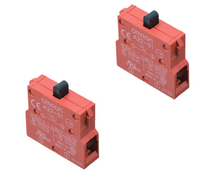
A22NE-PD

                                                                                                                              A22NE-PD
Accessories (Order Separately)
Operation Unit
Non-lighted
                                             Size       Small (30 dia.)          Medium (40 dia.)           Large (60-dia.)
Function            Degree of protection                                      Single item order model
                                                                              A22NE-MP-N

                 IP65 oil-resistant models                      ---                                                 ---

                                                                                                                              A22NE-P
Pull-reset
                                                                              A22NE-MP-N-69K

                 IP69K                                          ---                                                 ---

                                                                              A22NE-M-N

                                                                              A22NE-MRO-N

                                                                                                                              A22E
                                                    A22NE-S-N                 A22NE-MRO-N-RD            A22NE-L-N

Turn-reset       IP65 oil-resistant models

                                                                              A22NE-MRS-N
                                                                              A22NE-MRS-N-RD

                                                                                                                               Common Accessories and Tools
Lighted
                                             Size      Medium (40 dia.)
Function                Sealing capability          Single item order model
                                                    A22NE-M-L

Turn-reset       IP65
                                                                                                                              Common Note

                                                                                                                              9
A22NE-PD
A22NE-PD

                                LED lamp

                                   Appearance         LED light              Rated voltage                  Model                                Remarks

                                                                                                                             These are provided with the completely assembled
                                                        Red         24 V AC/DC                       A22NZ-L-RC              set of lighted models. Order LED Lamps only when
                                                                                                                             replacing them.

                                Control Box
A22NE-P

                                      Item                          Appearance                              Model                                Remarks

                                                                                                                             Material: Polycarbonate resin.
                                   Control Box                      One hole, yellow box             A22NZ-A-B101Y
                                                                                                                             For 22.3-mm panel hole diameter.

                                Note: For details on the accessories common to the screw terminal block models and push-in plus terminal block models, refer to "Common
                                      Accessories and Tools (Order Separately)" on page 51.
A22E
 Common Accessories and Tools
Common Note

                  10
A22NE-PD
Specifications
A22NE-PD
Certified Standard Ratings Certified Standards
• UL508 (File No. E76675), CSA C22.2 No.14
Certification
5 A at 125 VAC, 3 A at 250 VAC B300 Standards File No.
body
• TÜV (EN60947-5-1) - Certified direct opening -
UL * UL508, C22.2 No.14 E76675
(EN60947-5-5)
AC-15 3 A at 125 VAC EN60947-5-1
Consult your OMRON
TÜV SÜD (Certified direct opening),
DC-13 1 A at 30 VDC EN60947-5-5
representative for details.
• CCC (GB14048.5)
Consult your OMRON
AC-15 3 A at 125 VAC CQC (CCC) GB14048.5
representative for details.
DC-13 1 A at 30 VDC
Note: Only models with NC contacts have a direct opening
Applicable Standards mechanism.
UL1059, UL486E * UL-certification for CSA C22.2 No. 14 has been obtained.
A22NE-P
Note: Use a 10 A fuse type gI or gG that conforms to IEC60269 as a
short-circuit protection device. This fuse is not provided in the
main unit.
Ratings
Contacts (Standard Load) LED Lamp (A22NZ-L-RC)
Rated current (A) Rated voltage Operating voltage Current value
Rated Rated
Rated carry AC15 AC12 DC13 DC12 24 VAC/VDC 24 VAC/VDC ± 10% Approx. 12 mA
insulation voltage
current (A) (Inductive (Resistive (Inductive (Resistive
voltage (V) (V)
load) load) load) load)
30 VAC --- --- --- ---
125 VAC 3A 5A --- ---
250 VAC 1.5 A 3A --- ---
250 5
A22E
30 VDC --- --- 1A 2A
125 VDC --- --- 0.22 A 0.4 A
250 VDC --- --- 0.1 A 0.2 A
Note: 1. The above ratings were obtained by conducting tests under
the following conditions.
(1) Ambient temperature: 20°±2°C
(2) Ambient humidity: 65±5%
(3) Operating frequency: 20 operations/minute
2. Minimum applicable load: 1 mA at 5 VDC (Resistive load)
The operating range may vary depending on the usage
Common Accessories and Tools
conditions and type of load.
Common Note
11A22NE-PD
A22NE-PD
Characteristics
Operation Turn-reset Pull-reset
Non-lighted model
Non-lighted model Lighted Model Non-lighted model
(Models with IP69K)
Item A22NE-@-PD@@-N-@ A22NE-M-PD@@-C-@ A22NE-MP-PD@@-N-@ A22NE-MP-PD@@-N-69K
Allowable operating Mechanical 30 operations/minute or less (One operation consists of set and reset operations.)
frequency Electrical 30 operations/minute or less (One operation consists of set and reset operations.)
Insulation resistance *1 100 MΩ min. (at 500 VDC)
Contact resistance 100 mΩ max. (initial value)
Between
terminals of 2,000 VAC, 50/60 Hz 1 minute (initial value)
same polarity*1
A22NE-P
Between
Dielectric
terminals of 2,000 VAC, 50/60 Hz 1 minute (initial value)
strength
different polarity
Between each
terminal and 2,000 VAC, 50/60 Hz 1 minute (initial value)
ground
Vibration
Malfunction 10 to 55 Hz, 1.5 mm double amplitude (contact separation within 1 ms)
resistance
Shock
Malfunction 250 m/s2 max. (contact separation within 1 ms)
resistance
100,000 operations min.
Mechanical 300,000 operations min. (One operation consists of set and reset operations.) (One operation consists of
set and reset operations.)
Electrical 100,000 operations min.
(100 mA at 24
250,000 operations min. (One operation consists of set and reset operations.) (One operation consists of
A22E
Durability VAC (Resistive
load)) set and reset operations.)
Electrical
(3 mA at 250
100,000 operations min. (One operation consists of set and reset operations.)
VAC (Resistive
load))
Ambient operating temperature *2 -20 to +70°C -20 to +55°C -20 to +70°C -20 to +70°C *3
Ambient operating humidity 35 to 85% RH
Ambient storage temperature *2 -40 to +70°C
Degree of protection *4 IP65 oil-resistant models IP65 IP65 oil-resistant models IP69K
Common Accessories and Tools
Electric shock protection class Class II
PTI (tracking characteristic) 175
Degree of contamination 3 (EN 60947-5-1)
Minimum direct opening stroke 11 mm
Minimum direct opening force 45 N
Conditional short-circuit current 100 A (EN 60947-5-1)
Wight (for a 40-dia. head
Approx. 95 g Approx. 95 g Approx. 125 g Approx. 135 g
2NC/2NO Operation Unit)
*1. State when an LED is not added between terminals of the same polarity on a lighting unit.
*2. With no icing or condensation.
*3. Capable of operation at up to 80°C under IP@9K testing conditions per JIS D 5020.
*4. The degree of protection from the front of the panel.
Operating Characteristics
Common Note
Turn-reset Pull-reset
Item Non-lighted model
Lighted / non-lighted models Non-lighted model
(Models with IP69K)
Total travel force (TTF) 45 N max. 60 N max. 70 N max.
Return force (RF) 0.25N·m max. * 60 N max. 70 N max.
Total travel (TT) 10 ±1 mm 5.5 ±1 mm
* Rotation torque value.
12A22NE-PD
A22NE-PD
Terminal Arrangement (BOTTOM VIEW)
Non-lighted
One contact (1NC) Two contacts (2NC) Two contacts (1NC + 1NO)
A22NE-P
Three contacts (3NC) Three contacts Four contacts Four contacts (4NC)
(2NC + 1NO) (3NC + 1NO)
Lighted Terminal arrangement
The switch terminal is same as that in the non-lighted models.
Indicates the terminals for lighting (X1-X2). Terminal (insertion) hole Lock lever
(Example: Four contacts (4NC) Lighted models)
A22E
3.9 (0.3)
36.3
(0.3) 3.9
11 9 3.9
Common Accessories and Tools
31
35.9
Terminal Arrangement
Terminal Arrangement (BOTTOM VIEW)
Type
1NC, 1NO (two contacts) 2NC, 2NO (four contacts) 3NC, 1NO (four contacts) 4NC (four contacts)
NO NO NO NC NO NC NC
14 13 24 23 14 13 32 31 14 13 32 31 42 41
Non-lighted
NC NC NC NC NC
NC NC
12 11 22 21 12 11 22 21 12 11
22 21 12 11
Common Note
NO NO NO NC NO NC NC
14 13 24 23 14 13 32 31 14 13 32 31 42 41
Lighted X2 X1 X2 X1 X2 X1 X2 X1
NC NC NC NC NC NC NC
12 11 22 21 12 11 22 21 12 11 22 21 12 11
Note: The terminal arrangement shows the representative. It depends on the number of contacts in the series.
13A22NE-PD
Structure and Nomenclature
A22NE-PD
Operation Unit
Color: Red
Non-lighted
LED lighting
Lamp
Light source
• LED Lamp
A22NE-P
Switch
}
Mounting Latches
Switch Blocks
Lighting unit
Contact Ratings
3 A at 250 VAC
5 A at 125 VAC
Lighting Method
Non-lighted
Lighted (LED)
A22E
Common Accessories and Tools
Common Note
14A22NE-PD
Dimensions
A22NE-PD
(Unit: mm)
Non-lighted Models
A22NE-MP-PD@@-N A22NE-MP-PD@@-N-69K
Pull-reset (40-dia.) Degree of Protection: IP65 oil-resistant models Pull-reset (40-dia.) Degree of Protection: IP69K
40 dia. 45 40 dia. 45
1.8 1.8
(0.5) 5.9
5.9 32 54.7
32 55
A22NE-P
A22NE-S-PD@@-N A22NE-M-PD@@-N
Small Turn-reset (30-dia.) Degree of Protection: Medium Turn-reset (40-dia.) Degree of Protection:
IP65 oil-resistant models IP65 oil-resistant models
45 40 dia. 45
30 dia.
1.8 1.8
(0.5) (0.5)
5.9 5.9
32 55 32 55
Note: The dimensions the same even if the Operation Unit is replaced
with the A22NE-MR@-N or the A22NE-MR@-N-RD.
A22NE-L-PD@@-N
A22E
Large Turn-reset (60-dia.) Degree of Protection:
IP65 oil-resistant models
60 dia. 45
1.8
(0.5)
5.9
32 55
Common Accessories and Tools
Lighted Model
A22NE-M-PD@@-C
Medium Turn-reset (40-dia.) Degree of Protection: IP65
40 dia. 45
1.8
(0.5)
5.9
32 55
Common Note
Note: Unless otherwise specified, a tolerance of ±0.8mm applies to all dimensions.
Accessories (Order Separately)
LED Lamp
A22NZ-L-RC
24.3
9.8 dia.
9 dia.
Note: For details on the accessories common to the screw terminal block types and push-in plus terminal block types, refer to "Common
Accessories and Tools (Order Separately)" on page 51.
15A22NE-PD
Application
A22NE-PD
Mounting to the Panel
(1) Preparing the Panel (3) Mounting the Operation Unit on the Panel
Panel hole dimension and panel thickness • Do not tighten the Tightening Nut more than necessary using tools such as
• If outer surface treatment such as coating is performed for the panel, the panel pointed-nose pliers.
dimensions after outer surface treatment must meet the specified panel • Doing so will damage the Tightening Nut.
dimensions. (The tightening torque of the Tightening Nut is 1.0 to 2.0 N·m.)
Tightening Wrench: A22Z-3905
Panel Hole of 22.3-mm Diameter
Panel hole dimension Panel thickness
• Insert the Operation Unit from the front of the panel, insert the Lock Ring and
22.3 dia. 1 to 5 mm Tightening Nut from the back of the panel, and tighten the Tightening Nut.
Before tightening, check that the rubber washer is present between the
Operation Unit and the panel.
+0.4
22.3 0 dia.
A22NE-P
Tightening Nut
Lock Ring
Panel
When using a A22Z-3360 (Order Separately) Lock Ring
22.3 dia. Tightening Wrench
3.2 +0.2
0 (order separately, A22Z-3905)
R0.8 max.
22.3 dia. +0.4
0 Rubber Washer
+0.4
24.10
Hold here
Rubber washer
Tightening Nut
For 25-dia.
• Use the A22Z-R25 (Order Separately) rubber ring.
* Switches with an IP69K degree of protection do not support the 25-
dia.
Lock Ring
+0.5
25 0 dia.
Panel
A22E
When the A22Z-3360 Lock Ring (Order Separately) is used
• Take note of the direction when mounting the Lock Ring.
Panel
Projecting part
(2) Minimum mounting pitch (Dimension A, Dimension B)
Minimum mounting pitch
Lock Ring
Dimension A (mm) Dimension B (mm)
Type of operation unit
min. min. Panel Hole of 25-mm Diameter Panel Hole of 30-mm Diameter
30-dia., 40-dia. models 50 *1 50 • Insert the A22Z-R25 (Order • Insert the A22Z-A30 (Order
Separately) between the Operation Separately) between the Operation
60-dia. model 70 70
Common Accessories and Tools
Unit and Panel, and tighten the Unit and Panel, and tighten the
Tightening Nut. Tightening Nut.
*1. If the Switch Unit lock levers all face the same direction at the Before tightening, check that the Before tightening, check that the
minimum mounting pitch, be sure to note the order the Switch Units rubber washer supplied with the supplied rubber washer is present
Operation Unit is present between between the Operation Unit and
are attached to the Operation Unit.
the Operation Unit and the 25-dia. the panel, and between the 30-dia.
*2. When using each accessory (Order Separately), set the A and B Ring. Resin Attachment and the panel.
dimensions in view of the dimensions of the accessories.
* Switches with an IP69K degree of
*3. Make sure the mounting pitch does not hinder the operation. protection do not support the 30-
dia.
Panel Hole Dimensions for 22.3 Diameter Operation Unit
Operation Unit
3.2 +0.2
0
R0.8 max.
+0.4
22.3 0 dia.
Rubber washer Rubber Washer
(provided with the (provided with the
24.1+0.4
0 Operation Unit) Operation Unit)
Common Note
22 dia. 30-dia.
25-dia. Ring Resin Attachment
A22Z-R25
A22Z-A30
Rubber Washer
Dimension A (included)
Dimension B 24.8 dia.
0.5 1.3 Mounting Panel
27 dia.
+0.4 +0.4
22.3 0 dia. 22.3 0 dia.
Lock Ring
Tightening Nut
Panel
Lock Ring
Using the Standard switch
Tightening Nut
Lock Ring
Panel Cutouts Panel thickness
25 mm dia. 1 to 5 mm
30 mm dia. 1 to 3 mm
16A22NE-PD
A22NE-PD
Removing the Switch Unit Installing the LED Lamp (Lighted Models)
When the Switch Unit is to be Removed When the LED Lamp is to be Installed
Slowly push the release port (concave part) of the lock lever with a Insert the protrusions on the LED Lamp into the guides on the Switch Unit in
screwdriver to release the lock. The lock lever moves to the release position. direction (1), and then turn the LED Lamp in direction (2) to lock it in place.
2 1
Lock lever concave part
A22NE-P
Release position Locked position
When the lock lever is at the released position in this Switch, the NO and NC
contact operation is reversed.
Set the lock lever to the locked position when using the Switch.
A22E
Common Accessories and Tools
Common Note
17A22NE-PD
Safety Precautions
A22NE-PD
Be sure to read the precautions for All PushButton Switches in the website at: http://www.ia.omron.com/.
Indication and Meaning for Safe Use • Do not disassemble or modify the Switch/Indicator under any
circumstances.
Indicates a potentially hazardous • Doing so may prevent the Switch/Indicator from functioning to its
situation that, if not avoided, could full capability. Do not drop the Switch/Indicator. Do not apply
Warning result in serious injury or death. pressure that may deform or alter the Switch/Indicator.
Additionally there may be significant • The durability of the Switch varies considerably depending on the
property damage. switching conditions. Always test the Switch/Indicator under actual
working conditions before application and use the Switch/Indicator
Precautions for Comments on what to do or avoid doing, to only for the number of switching operations allowed.
Safe Use use the product safely. • Do not allow the load voltage and current to exceed the rated
value. This may damage or burn out the Switch/Indicator.
Supplementary comments on what to do or • Do not use the Switch/Indicator in locations where explosive or
A22NE-P
Precautions for avoid doing to use the product safely and flammable gases or liquid may be present or scattered. The
Correct Use prevent its malfunctioning or an adverse
effect on its performance or functions. electric ark or the heat caused by switching contacts may cause a
fire or explosion.
WARNING • Do not use the Switch/Indicator in locations where toxic gases,
such as H2S, SO2, NH3, HNO3, and Cl2, may be present, or in
Do not perform wiring with power supplied to the Switch/ locations subject to high temperature or humidity. Doing so may
Indicator. Do not touch the terminals or other charged
parts while power is being supplied. Doing so may result damage the Switch/Indicator due to contact failure or corrosion.
in electric shock. • Do not use the Switch/Indicator submersed in oil or water, or in
locations continuously subject to splashes of oil or water. Doing so
Precautions for Safe Use may result in oil or water entering and damaging the Switch/
Indicator.
• Make sure the Operation Unit and the Switch Unit are properly
• Do not use or keep the Switch/Indicator under the following
assembled.
conditions:
• Subject to severe temperature changes.
• Subject to high humidity or condensation.
(1) Assembling the Operation Unit and Switch Unit
• Subject to severe vibration or shock.
A22E
Align the TOP indication (the mark ) on the Operation Unit
• Where direct rays of the sun strike.
with the TOP indication on the Switch Unit, and insert the
• Where sea breeze may be present.
Operation Unit while keeping the bottom A pressed.
• Make sure that a rubber washer is present between the Operation
(2) Locking the lock lever
Unit and the panel. In models with IP69K, make sure the rubber
With a screwdriver inserted in the lock hole of the lock lever,
bush of the Operation Unit is properly attached.
bring the screwdriver in contact with the convex part of the
Otherwise, the specifications of the protective structure may not be
case, and turn the lock lever until a clicking sound is heard.
satisfied.
(1) Mark (2) • Do not apply excessive force to the Switch or wirings. Damage or
Operation Unit
Lock Hole of Lock Lever deformation of the Switch Unit could result in an improper contact
or a loss of safety.
• Use an appropriate wiring and crimp terminals (hereinafter, called
Common Accessories and Tools
TOP indication ferrule terminals).
(1) BD
• Exercise caution to avoid wiring errors when connecting the
terminals.
• To prevent wiring materials from smoking or ignition, confirm wire
Convex Part ratings and use the wiring materials given in the following table.
Wire Recommended Wire coating peeling
Wire Type
material Wire amount
(2) Switch Unit
Bottom A Ferrules used: 10 to 12 mm
Solid wire/ (Varies depending on the
0.25 to 1.5 mm2
Stranded Copper recommended ferrule
AWG 24 to 16
Wire conductor length)
Ferrules not used: 8 mm
Use wiring crimp terminals and ferrule terminals of the specified
size.
Common Note
Release position Locked position
When the lock lever is at the released position in
this Switch, the NO and NC contact operation is
reversed.
Set the lock lever to the locked position when us-
ing the Switch.
• When transition wiring is performed, make sure the switching
current inside the Switch and the current based on the transition
wiring is below the rated current of the Switch.
If a current value higher than the rated current flows, it could result
in emission of heat, or damage and deformation of the Switch,
which could cause fire and locking of the contact, and thus a loss
of safety.
18A22NE-PD
A22NE-PD
• After storing the product for a long time exceeding 1 year, perform,
at a minimum, inspections of the operating characteristics, contact Precautions for Correct Use
resistance, insulation resistance, and dielectric strength as well as
evaluate the product under the working conditions. Wiring
• This product is intended for indoor use only. Using the product 1. Connecting Wires to the Push-In Plus Terminal Block
outdoors will result in failure. Part Names of the Terminal Block
• Do not wire anything to the release holes.
• Do not tilt or twist a flat-blade screwdriver while it is inserted into a
release hole on the terminal block. The terminal block may be
damaged.
• Insert a flat-blade screwdriver into the release holes at an angle. Release Terminal
hole (insertion) hole
The terminal block may be damaged if you insert the screwdriver
straight in.
• Do not allow the flat-blade screwdriver to fall out while it is inserted
A22NE-P
into a release hole.
• Do not bend a wire past its natural bending radius or pull on it with
excessive force.
Doing so may cause the wire disconnection.
• Do not insert more than one wire into each terminal insertion hole.
• When mounting on a device with high airtightness, test operation
in advance. There is a risk that the negative pressure will prevent
the Operation Unit of from returning.
• Although the contacts of an A22NE-PD can be used with both the Connecting Wires with Ferrules and Solid Wires
standard loads and microloads, once a contact has opened or • Insert the solid wire or ferrule straight into the terminal block until
closed under a load, you cannot again connect a small-capacity the end strikes the terminal block.
load. Doing so could roughen the contact surface, and result in loss • If a wire is difficult to connect because it is too thin, use a flat-blade
of contact reliability. screwdriver in the same way as when connecting stranded wires.
• In the case of loads where an inrush current occurs when the
contact is opened or closed, the durability may reduce due to
extreme wear on the contacts.
A22E
If necessary, insert a contact protection circuit.
• If a contact weld, the lock lever might not return to the release
position, and contact inversion might not occur. In such a case, Ferrule terminal or
move the lock lever to the release position, and remove the Switch solid wire
Unit from the Operation Unit.
Common Accessories and Tools
Connecting Stranded Wires
Use the following procedure to connect the wires to the terminal
block.
1. Hold a flat-blade screwdriver at an angle and insert it into the
release hole. The angle should be appropriately 10 to 15°. If the
flat-blade screwdriver is inserted correctly, you will feel the spring
in the release hole.
2. With the flat-blade screwdriver still inserted into the release hole,
insert the wire into the terminal hole until the end strikes the
terminal block.
3. Remove the flat-blade screwdriver from the release hole.
(2)
Approx.
10 to 15°
Common Note
(1)
(3)
Flat-head screwdriver
19A22NE-PD
A22NE-PD
Checking Connections Recommended Flat-Blade Screwdrivers
• After the insertion, pull gently on the wire to make sure that it will Use a flat-blade screwdriver to connect and remove wires.
not come off and it is securely fastened to the terminal block. Use one of the following flat-blade screwdrivers.
• If you use a ferrule with a conductor length of 10 mm, part of the The following table shows manufacturers and models as of 2015/Dec.
conductor may be visible after the ferrule is inserted into the Side view Front view
terminal block, but the product insulation distance will still be
satisfied. 2.5 mm dia.
2. Removing Wires from the Push-In Plus Terminal Block
Use the following procedure to remove wires from the terminal block.
The same method is used to remove stranded wires, solid wires, and ferrules.
0.4 mm 2.5 mm
1. Hold a flat-blade screwdriver at an angle and insert it into the
release hole. The angle should be appropriately 10 to 15°. Model Manufacture
2. With the flat-blade screwdriver still inserted into the release hole,
A22NE-P
remove the wire from the terminal insertion hole. ESD 0,40 × 2,5 Wera
3. Remove the flat-blade screwdriver from the release hole. SZS 0,4 × 2,5
Phoenix Contact
SZF 0-0,4 × 2,5 *
(2) 0.4 × 2.5 × 75 302 Wiha
Approx. AEF.2,5 × 75 Facom
10 to 15°
(1) 210-719 Wago
SDI 0,4 × 2,5 × 75 Weidmuller
(3) * The SZF 0-0,4 × 2,5 (manufactured by Phoenix Contact) can be
procured through an OMRON exclusive purchase form (XW4Z-00B).
Flat-head screwdriver
• After wiring the Switch/Indicator, provide a sufficient insulation
distance.
LED Lamps
• A current-limiting resistor is built in the LED lamp, so the
A22E
3. Recommended Ferrules and Crimp Tools installation of an external resistance is not required.
Coating peeling amount • Lighting malfunction of the LED lamp
Stripping length A micro-current of approximately 0.1 mA or less is sufficient to turn
Recommend Wire Type on the LED lamps. Take a countermeasure like adding a resistor to
(Ferrules not used)
0.25 to 1.5 mm2/AWG 24 to AWG 16 8 mm prevent mis-lighting in parallel to the LED lamp.
The micro-current varies with the machine (leak current or stray
capacity between cables, etc.). Select resistance value and
Recommended ferrules
allowable power consumption that meet the actual current.
Applicable
Ferrule Stripping Recommended ferrules
wire (Example of lighting malfunction prevention circuit)
conductor length (mm)
Phoenix When using a 24 VAC/DC Lighted Model
length (Ferrules not
Common Accessories and Tools
Weidmuller Wago
(mm2) (AWG) (mm) used) Contact
product product
product X1
8 10 AI 0, 25-8 H0.25/12 216-301
0.25 24 LED R:10 kΩ (1 W)
10 12 AI 0, 25-10 --- --- lamp Bleeder resistor
8 10 AI 0, 34-8 H0.34/12 216-302
0.34 22 X2
10 12 AI 0, 34-10 --- ---
Be sure to read the "Safety Precautions" on page 56.
8 10 AI 0, 5-8 H0.5/14 216-201
0.5 20
10 12 AI 0, 5-10 H0.5/16 216-241
8 10 AI 0, 75-8 H0.75/14 216-202
0.75 18
10 12 AI 0, 75-10 H0.75/16 216-242
8 10 AI 1-8 H1.0/14 216-203
1/1.25 18/17
10 12 AI 1-10 H1.0/16 216-243
Common Note
8 10 AI 1, 5-8 H1.5/14 216-204
1.25/1.5 17/16
10 12 AI 1, 5-10 H1.5/16 216-244
CRIMPFOX6
Variocri
Recommended Crimp Tools CRIMPFOX6T-F PZ6 roto
mp4
CRIMPFOX10S
Note: 1. Make sure that the outer diameter of the wire coating is
smaller than the inner diameter of the insulation sleeve of
the recommended ferrule.
2. Make sure that the ferrule processing dimensions conform
to the following figures.
8 to 10 mm
Max. 1.9 mm Max. 2.6 mm
20Emergency Stop Pushbutton Switches (22-dia. or 25-dia.) Push-in Plus Terminal Block Models
A22NE-P
A22NE-PD
Install in 22-dia. or 25-dia. Panel Cutout
(When Using a Ring)
• The small size of the control panel is realized by conserving space
and changing the direction of the wiring.
• Since there is no looseness in the wiring, there is a reduction in the
maintenance efforts.
• A lock lever mechanism that can be easily operated is adopted.
• A maximum of up to six contact points can be combined together
in the contact-point configuration.
A22NE-P
• Oil-resistant to IP65 (non-lighted models) / IP65 (lighted models) /
Supports IP69K high-temperature, high-pressure cleaning (pull- For the most recent information on models that have been
certified for safety standards, refer to your OMRON website.
reset models).
Be sure to read the "Safety Precautions" on pages 33 and 56.
Model Number Structure
Model Number Legend (Completely Assembled) ........ Shipped as a set which includes the Operation Unit, LED
Lamp (lighted model only), Mounting Latches, Lighting
Units (lighted model only), and Switch Block.
1 2 3 4 5 6
A22NE- - - - (Example: A22NE-M-P102-N)
A22E
1. Operation Unit size (diameter) 4. Contacts
Code Description Number of Unit position
S 30 dia. Code Switch Blocks Non-lighted Lighted
M 40 dia. NO NC 1 2 3 1 2 3
L 60 dia.
002 0 1 --- --- NC --- Lighting unit NC
102 1 1 NO --- NC NO Lighting unit NC
2. Reset function 202 0 2 NC --- NC NC Lighting unit NC
Common Accessories and Tools
Code Description 212 1 2 NC NO NC
---
None Turn-reset 222 0 3 NC NC NC
P Pull-reset *
Note 1. NO: 1a-contact NC: 1b-contact
* The pull-reset type is only available on the 40 dia. 2. For details on the unit position, refer to the figure below.
Operation Unit, non-lighted type.
Not available on lighted types.
3. Contact specification/Terminal specification
Code Description
P Standard load/Push-in plus terminal block
5. LED lamp voltage
Common Note
Code Description LED Lamp Voltage
N Non-lighted ---
A 6 VAC/DC
B 12 VAC/DC
Lighted
C (LED) * 24 VAC/DC
D 100/110/120 VAC
E 200/220/230/240 VAC
* Lighting color is red.
6. Others (Degree of Protection/Control box)
Code Configuration
None IP65
69K IP69K
B* Built-in control box
* One-contact unit type.
21A22NE-P
Ordering Information
A22NE-PD
List of Models (Completely Assembled)
Non-lighted Models
Appearance Operation Degree of Protection Contact configuration * Set Model Color of cap
1NC (1) A22NE-MP-P002-N
1NC, 1NO (2) A22NE-MP-P102-N
40-dia. head
IP65 oil-resistant
Medium Pull-reset models
2NC (2) A22NE-MP-P202-N
A22NE-MP-P@@2-N
2NC, 1NO (3) A22NE-MP-P212-N
3NC (3) A22NE-MP-P222-N
1NC (1) A22NE-MP-P002-N-69K
1NC, 1NO (2) A22NE-MP-P102-N-69K
40-dia. head
Medium Pull-reset IP69K 2NC (2) A22NE-MP-P202-N-69K
A22NE-MP-P@@2-N-69K
A22NE-P
2NC, 1NO (3) A22NE-MP-P212-N-69K
3NC (3) A22NE-MP-P222-N-69K
1NC (1) A22NE-S-P002-N
1NC, 1NO (2) A22NE-S-P102-N
30-dia. head
Small Turn-reset 2NC (2) A22NE-S-P202-N Red
A22NE-S-P@@2-N
2NC, 1NO (3) A22NE-S-P212-N
3NC (3) A22NE-S-P222-N
1NC (1) A22NE-M-P002-N
1NC, 1NO (2) A22NE-M-P102-N
40-dia. head
Medium Turn-reset IP65 oil-resistant 2NC (2) A22NE-M-P202-N
models
A22NE-M-P@@2-N
2NC, 1NO (3) A22NE-M-P212-N
3NC (3) A22NE-M-P222-N
1NC (1) A22NE-L-P002-N
1NC, 1NO (2) A22NE-L-P102-N
60-dia. head
A22E
Large Turn-reset 2NC (2) A22NE-L-P202-N
A22NE-L-P@@2-N
2NC, 1NO (3) A22NE-L-P212-N
3NC (3) A22NE-L-P222-N
* The number in parentheses ( ) indicates the number of switch units.
Lighted Model
Appearance Operation Degree of Contact LED lamp voltage Set Model Color of cap
Protection configuration *
1NC (1) A22NE-M-P002-A
40-dia. head
Medium Turn-reset 1NC, 1NO (2) 6 VAC/VDC A22NE-M-P102-A
A22NE-M-P@@2-A
Common Accessories and Tools
2NC (2) A22NE-M-P202-A
1NC (1) A22NE-M-P002-B
40-dia. head
Medium Turn-reset 1NC, 1NO (2) 12 VAC/VDC A22NE-M-P102-B
A22NE-M-P@@2-B
2NC (2) A22NE-M-P202-B
1NC (1) A22NE-M-P002-C
40-dia. head
Medium Turn-reset IP65 1NC, 1NO (2) 24 VAC/VDC A22NE-M-P102-C Red
A22NE-M-P@@2-C
2NC (2) A22NE-M-P202-C
1NC (1) A22NE-M-P002-D
40-dia. head
Medium Turn-reset 1NC, 1NO (2) 100, 110, 120 VAC A22NE-M-P102-D
A22NE-M-P@@2-D
2NC (2) A22NE-M-P202-D
Common Note
1NC (1) A22NE-M-P002-E
40-dia. head
Medium Turn-reset 1NC, 1NO (2) 220, 230, 240 VAC A22NE-M-P102-E
A22NE-M-P@@2-E
2NC (2) A22NE-M-P202-E
* The number in parentheses ( ) indicates the number of switch units.
Switch with Integrated Control Box
Appearance Contact configuration (Number of switch blocks) Model
1NC (1) A22NE-M-P002-N-B
1NC, 1NO (2) A22NE-M-P102-N-B
2NC (2) A22NE-M-P202-N-B
22A22NE-P
A22NE-PD
Subassembled ........ The Operation Unit, LED Lamp, Mounting Latches, Switch Blocks, and Lighting Unit can be ordered separately. Use
them in combination for models that are not available as assembled Units. These can also be used as inventory for
maintenance parts.
Non-lighted Lighted
Operation Unit Operation Unit
A22NE-P
Mounting Latches
A22E
LED Lamp
Common Accessories and Tools
Switch Blocks * Switch Blocks + Lighting Unit
Push-in Plus Terminal Block Push-in Plus Terminal Block
Common Note
* Up to three Switch Blocks can be mounted.
23A22NE-P
A22NE-PD
Operation Unit
Non-lighted
Size Small (30 dia.) Medium (40 dia.) Large (60-dia.)
Function Sealing capability Single item order model
A22NE-MP-N
IP65 oil-resistant models --- ---
Pull-reset
A22NE-MP-N-69K
A22NE-P
IP69K --- ---
A22NE-M-N
A22NE-MRO-N
A22NE-S-N A22NE-MRO-N-RD A22NE-L-N
A22E
Turn-reset IP65 oil-resistant models
A22NE-MRS-N
A22NE-MRS-N-RD
Common Accessories and Tools
Lighted
Size Medium (40 dia.)
Function Sealing capability Single item order model
A22NE-M-L
Turn-reset IP65
Common Note
LED lamp
Appearance LED light Rated voltage Model Remarks
6 VAC/VDC A22NZ-L-RA
These LED lamps are for
12 VAC/VDC A22NZ-L-RB exclusive use with the A22N
and the A22NE-P. These are
Red 24 VAC/VDC A22NZ-L-RC provided with the completely
assembled set of lighted
100, 110, 120 VAC A22NZ-L-RD models. Order LED lamps only
when replacing them.
200, 220, 230, 240 VAC A22NZ-L-RE
24A22NE-P
A22NE-PD
Accessories (Order Separately)
Item Appearance Contact specifications Model Remarks
1NO (Blue) Standard load A22NZ-S-P1AN Provided as standard.
Switch Blocks
Order Switch Blocks only when
(one contact)
1NC (Red) Standard load A22NZ-S-P1BN adding or replacing them.
2NC (Red) Standard load A22NZ-S-P2BN
Switch Blocks Order Switch Blocks only when
(two contacts) adding or replacing them.
1NO/1NC
Standard load A22NZ-S-P2CN
(White)
A22NE-P
6 VAC/VDC A22NZ-T-APN
12 VAC/VDC A22NZ-T-BPN These are provided with the
completely assembled set of
Lighting unit 24 VAC/VDC A22NZ-T-CPN
lighted models. Order Lighting
100, 110, 120 VAC A22NZ-T-DPN Units only when replacing them.
200, 220, 230, 240 VAC A22NZ-T-EPN
This Mounting Latch is for
exclusive use with the A22NE-P.
It is provided with the completely
Mounting assembled set.
--- A22NZ-H-02
Latches Order Mounting Latches only
when mounting Switch Blocks or
Lighting Units that are
purchased individually.
Can be combined with 2-contact
A22E
A22NZ-A-B101Y
Switch Blocks.
Control Boxes
One hole, yellow box
(Enclosures)
Cannot be combined with
A22NZ-A-B01Y
2-contact Switch Blocks. *
Note: For details on the accessories common to the screw terminal block types and push-in plus terminal block types, refer to "Common
Accessories and Tools (Order Separately)" on page 51.
* The A22NZ-A-B01Y Control Box cannot be used in combination with the A22Z-3476-1 90-dia. Legend Plates for Emergency Stop or the A22Z-
EG@ E-stop Shrouds.
Common Accessories and Tools
Common Note
25A22NE-P
Specifications
A22NE-PD
Certified Standard Ratings Certified Standards
• UL508 (File No. E76675), CSA C22.2 No.14
Certification
6 A at 240 VAC, 10 A at 120 VAC Standards File No.
body
• TÜV (EN60947-5-1) - Certified direct opening -
UL * UL508, C22.2 No.14 E76675
(EN60947-5-5)
AC-15 3 A at 240 VAC EN60947-5-1
Consult your OMRON
TÜV SÜD (Certified direct opening),
DC-13 4 A at 24 VDC EN60947-5-5
representative for details.
• CCC (GB14048.5)
CQC (CCC) GB14048.5 2017010305959182
AC-15 3 A at 240 VAC
DC-13 4 A at 24 VDC
Note: Only models with NC contacts have a direct opening
mechanism.
Applicable Standards * UL-certification for CSA C22.2 No. 14 has been obtained.
UL1059, UL486E (Push-in Plus Terminal Block Types)
A22NE-P
Note: Use a 10 A fuse type gI or gG that conforms to IEC60269 as a
short-circuit protection device. This fuse is not provided in the
main unit.
Ratings
Contacts (Standard Load) LED Lamp
Rated voltage Operating voltage Current value
Rated current (A)
Rated Rated 6 VAC/VDC 6 VAC/VDC ± 10% Approx. 11 mA
Rated carry
insulation voltage AC15 AC12 DC13 DC12
current (A) 12 VAC/VDC 12 VAC/VDC ± 10% Approx. 12 mA
voltage (V) (V) (Inductive (Resistive (Inductive (Resistive
load) load) load) load) 24 VAC/VDC 24 VAC/VDC ± 10% Approx. 12 mA
24 VAC 10 10 100 VAC 100 VAC ± 10%
120 VAC 6 10 110 VAC 110 VAC ± 10% Approx. 12 mA
240 VAC 3 6 --- --- 120 VAC 100 VAC to 130 VAC
A22E
380 VAC 1.9 2 200 VAC 200 VAC ± 10%
600 10
440 VAC 1.6 2 220 VAC 220 VAC ± 10%
Approx. 12 mA
24 VDC 4 8 230 VAC 230 VAC ± 10%
120 VDC --- --- 1.1 2.2 240 VAC 220 VAC to 250 VAC
240 VDC 0.55 1.1
Note: 1. The above ratings were obtained by conducting tests under
the following conditions.
(1) Ambient temperature: 20°±2°C
(2) Ambient humidity: 65±5%
Common Accessories and Tools
(3) Operating frequency: 20 operations/minute
2. Minimum applicable load: 10 mA at 5 VDC (Resistive load)
The operating range may vary depending on the usage
conditions and type of load.
Common Note
26A22NE-P
A22NE-PD
Characteristics
Operation Turn-reset Pull-reset
Non-lighted model Lighted Model Non-lighted model
Item A22NE-@-P@@@-N A22NE-M-P@@@-@ A22NE-MP-P@@@-N A22NE-MP-P@@@-N-69K
Allowable operating Mechanical 30 operations/minute or less (One operation consists of set and reset operations.)
frequency Electrical 30 operations/minute or less (One operation consists of set and reset operations.)
Insulation resistance *1 100 MΩ min. (at 500 VDC)
Contact resistance 100 mΩ max. (initial value)
Between terminals
2,500 VAC, 50/60 Hz 1 minute (initial value)
of same polarity*1
Dielectric
strength Between each
A22NE-P
terminal and 2,500 VAC, 50/60 Hz 1 minute (initial value)
ground
Vibration
Malfunction 10 to 55 Hz, 1.5 mm double amplitude (contact separation within 1 ms)
resistance
Shock
Malfunction 250 m/s2 max. (contact separation within 1 ms)
resistance
100,000 operations min.
300,000 operations min. (One operation consists of set and reset
Mechanical (One operation consists of
operations.)
set and reset operations.)
Durability
100,000 operations min.
300,000 operations min. (One operation consists of set and reset
Electrical (One operation consists of
operations.)
set and reset operations.)
Ambient operating temperature *2 -20 to +70°C -20 to +55°C -20 to +70°C -20 to +70°C *3
Ambient operating humidity 35 to 85% RH
Ambient storage temperature *2 -40 to +70°C
A22E
Degree of protection *4 IP65 oil-resistant models *5 IP65 IP65 oil-resistant models *5 IP69K
Electric shock protection class Class II
PTI (tracking characteristic) 175
Degree of contamination 3 (EN 60947-5-1)
Minimum direct opening stroke 11 mm
Minimum direct opening force 45 N
Conditional short-circuit current 100 A (EN 60947-5-1)
Wight (for a 40-dia. head
Approx. 55g Approx. 60g Approx. 85 g Approx. 115 g
1NC/1NO Operation Unit)
Common Accessories and Tools
*1. State when an LED is not added between terminals of the same polarity on a lighting unit. Does not apply to lighted-type 100 to 200 V lighting units.
*2. With no icing or condensation.
*3. Capable of operation at up to 80°C under IP@9K testing conditions per JIS D 5020.
*4. The degree of protection from the front of the panel.
*5. The degree of protection is IP65 even with an integrated control box, but the system is not oil resistant.
Operating Characteristics
Turn-reset Pull-reset
Item
Lighted / non-lighted models Non-lighted model Non-lighted model (Models with IP69K)
Total travel force (TTF) 45 N max. 60 N max. 70 N max.
Return force (RF) 0.25N·m * max. 60 N max. 70 N max.
Total travel (TT) 10 ±1 mm 5.5 ±1 mm 5.5 ±1 mm
* Rotation torque value.
Terminal Arrangement (BOTTOM VIEW)
Common Note
Non-lighted (two contacts) Non-lighted (three contacts) Lighted (two contacts)
(20°) (20°) (20°)
(17.6°) Lock lever (17.6°) Lock lever (17.6°) Lock lever
Terminal Terminal Terminal
(insertion) hole (insertion) hole (insertion) hole
31.9 31.9 31.9
Switch Blocks Switch Blocks Switch Blocks
10 4 10 4 10 4
20 20 20 Lighting unit
27A22NE-P
A22NE-PD
Terminal connection
Terminal Connection (BOTTOM VIEW)
Type
1NC, 1NO (two contacts) 2NC (two contacts) 2NC, 1NO (three contacts) 3NC (three contacts)
NC NO NC NC NC NC NO NC NC NC
1 3 1 1 1 1 3 1 1 1
Non-lighted
2 4 2 2 2 2 4 2 2 2
1 X1 3 1 X1 1
A22NE-P
Lighted X X
2 X2 4 2 X2 2
Note: The above terminal connection diagrams are examples for 1NO, 1NC (two contacts), or 2NC (two contacts).
Terminal wiring drawings of two-contact Switch Units
Terminal Connection (BOTTOM VIEW)
Type
2NC (two contacts) 1NC, 1NO (two contacts)
21 21
A B A
A22E
22 22
11 13
B
12 14
Common Accessories and Tools
Structure and Nomenclature
Operation Unit
Color: Red
Non-lighted
LED lighting
Lamp
Light source
• LED Lamp
Common Note
Switch
}
Mounting Latches
Switch Blocks
Lighting unit
Contact Ratings
6 A at 240 VAC
10 A at 120 VAC
Lighting Method
Non-lighted
Lighted (LED)
28A22NE-P
Dimensions
A22NE-PD
(Unit: mm)
Non-lighted Models
A22NE-MP-P@@2-N A22NE-MP-P@@2-N-69K
Pull-reset (40-dia.) Degree of Protection: IP65 oil-resistant models Pull-reset (40-dia.) Degree of Protection: IP69K
40 dia. 42.5 40 dia. 42.5
1.8 5.9
(0.5)
1.8
5.9
32 39
A22NE-P
32 39.5
A22NE-S-P@@2-N A22NE-M-P@@2-N
Small Turn-reset (30-dia.) Degree of Protection: Medium Turn-reset (40-dia.) Degree of Protection:
IP65 oil-resistant models IP65 oil-resistant models
30 dia. 42.5 40 dia. 42.5
1.8 1.8
(0.5) (0.5)
5.9 5.9
32 39.5 32 39.5
Note: The dimensions the same even if the Operation Unit is
replaced with the A22NE-MR@-N or the A22NE-MR@-N-RD.
A22E
A22NE-L-P@@2-N
Large Turn-reset (60-dia.) Degree of Protection:
IP65 oil-resistant models
60 dia. 42.5
Common Accessories and Tools
1.8
(0.5)
5.9
32 39.5
Lighted Model
A22NE-M-P@@2-@ Dimensions when a two-contact Switch Block is attached
Medium Turn-reset (40-dia.) Degree of Protection: IP65
40 dia. 44
40 dia. 42.5
Common Note
(0.5)
1.8 5.9
(0.5) 1.8
5.9 32 55
32 39.5
Note: Unless otherwise specified, a tolerance of ±0.8 mm applies to all dimensions.
29A22NE-P
A22NE-PD
Accessories (Order Separately)
Switch Block with Push-In Plus technology
Switch Block (one contact) Switch Block (two contacts)
A22NZ-S-P1@N A22NZ-S-P2@N
4 4
5 5
23.8
16.4
39.3
31.9
47.6 9.9
A22NE-P
47.6 9.9
Lighting unit Mounting Latches R29.5
A22NZ-T-@PN A22NZ-H-02
12 dia.
30
26.4
23.8
16.4
47.6 9.9
17.1
A22E
51.3
LED Lamp
A22NZ-L-@@
24.3
9.8 dia.
9 dia.
Common Accessories and Tools
Control Box Four, M4 Phillips binding screws
Four, 3.7-dia.
40 (M4-tapped holes)
A22NZ-A-B01Y 24.2 22.3 dia. Cover (Yellow)
Case (Black)
10 Two, 14-dia.
(Bottom lead hole)
Two, 21.4 dia.
(Side lead hole)
Two, 4.4-dia.
(oval mounting hole)
24.2 80 62
3.2
18.5
5.4
3.2
10
38
80 40
Common Note
59.9
Control Box Four, M4 Phillips binding screws
Cover (Gray) Case (Black)
A22NZ-A-B101Y 24.2 22.3 dia.
Two, 16.1-dia.
(Bottom lead hole)
46.5 15.5 Two, 4.4-dia.
24.2 80 62 (Oval mounting hole)
3.2
20
3.2 5.4
Two, 21.3 dia.
80 47.5 2 40
(Side lead hole)
42
69.5
Note: For details on the accessories common to the screw terminal block types and push-in plus terminal block types, refer to "Common
Accessories and Tools (Order Separately)" on page 51.
30A22NE-P
Application
A22NE-PD
Mounting to the Panel
(1) Preparing the Panel (3) Mounting the Operation Unit on the Panel
Panel hole dimension and panel thickness • Do not tighten the Tightening Nut more than necessary using tools such as
• If outer surface treatment such as coating is performed for the panel, the panel pointed-nose pliers.
dimensions after outer surface treatment must meet the specified panel • Doing so will damage the Tightening Nut.
dimensions. (The tightening torque of the Tightening Nut is 1.0 to 2.0 N·m.)
Tightening Wrench: A22Z-3905
Panel Hole of 22.3-mm Diameter
Panel hole dimension Panel thickness
• Insert the Operation Unit from the front of the panel, insert the Lock Ring and
22.3 dia. 1 to 5 mm Tightening Nut from the back of the panel, and tighten the Tightening Nut.
Before tightening, check that the rubber washer is present between the
Operation Unit and the panel.
+0.4
22.3 0 dia.
A22NE-P
Tightening Nut
Lock Ring
Panel
When using a A22Z-3360 (Order Separately) Lock Ring 22.3 dia. Tightening Wrench
(order separately, A22Z-3905)
3.2 +0.2
0
R0.8 max.
Rubber Washer
22.3 dia. +0.4
0
Hold here
Rubber washer
24.1+0.4
0
Tightening Nut
For 25-dia.
• Use the A22Z-R25 (Order Separately) rubber ring.
* Switches with an IP69K degree of protection do not support the 25- Lock Ring
dia.
Panel
A22E
+0.5
25 0 dia. When the A22Z-3360 Lock Ring (Order Separately) is used
• Take note of the direction when mounting the Lock Ring.
Panel
Projecting part
(2) Minimum mounting pitch (Dimension A, Dimension B)
Lock Ring
Minimum mounting pitch
Dimension A (mm) Dimension B (mm) Panel Hole of 25-mm Diameter Panel Hole of 30-mm Diameter
Type of operation unit
min. min.
• Insert the A22Z-R25 (Order • Insert the A22Z-A30 (Order
Common Accessories and Tools
30-dia., 40-dia. models 50 *1 50 Separately) between the Separately) between the Operation
Operation Unit and Panel, and Unit and Panel, and tighten the
60-dia. model 70 70
tighten the Tightening Nut. Tightening Nut.
Before tightening, check that the Before tightening, check that the
*1. If the Mounting Collar lock levers all face the same direction at the rubber washer supplied with the supplied rubber washer is present
minimum mounting pitch, be sure to note the order the mounting Operation Unit is present between between the Operation Unit and
the Operation Unit and the 25-dia. the panel, and between the 30-dia.
collars are attached to the Operation Unit. Ring. Resin Attachment and the panel.
*2. When using each accessory (Order Separately), set the A and B Operation Unit * Switches with an IP69K degree of
dimensions in view of the dimensions of the accessories. protection do not support the 30-dia.
*3. Make sure the mounting pitch does not hinder the operation.
Operation Unit
Panel Hole Dimensions for 22.3 Diameter
3.2 +0.2
0 Rubber washer
R0.8 max. (provided with the
Operation Unit)
+0.4 Rubber Washer
22.3 0 dia.
22 dia. (provided with the
25-dia. Ring Operation Unit)
Common Note
24.1+0.4
0
A22Z-R25
30-dia.
24.8 dia. Resin Attachment
0.5 1.3 A22Z-A30
27 dia. Rubber Washer
(included)
Dimension A Mounting Panel
Dimension B
+0.4 +0.4 Lock Ring
22.3 0 dia. 22.3 0 dia.
Panel Tightening Nut
Lock Ring
Tightening Nut
Using the Standard switch
Lock Ring Panel Cutouts Panel thickness
25 mm dia. 1 to 5 mm
30 mm dia. 1 to 3 mm
31A22NE-P
A22NE-PD
Removing the Mounting Latch Attaching the LED Lamp to the Lighting Unit
When the Mounting Latch is to be Removed When the LED Lamp is to be Installed
• Press the lock lever in from the back side to release the lock, and then hook • Insert the protrusions on the LED Lamp into the guides on the Lighting Unit
the Mounting Collar with a screwdriver, move it in the direction indicated at and then turn the LED Lamp in direction (2) to lock it in place.
(2), and remove it. Turn the lever all of the way until it clicks into place.
(1)
2 1
A22NE-P
(2)
(3)
Control Box
(1) Mounting the Switch
Mount the Switch in the same way as for a standard panel.
Switch Blocks and Lighting Unit The tightening torque of the Box screws is 1.4 to 2.0 N·m.
(1) Installing the Switch Blocks and Lighting Unit Legend Plate
• Catch the projection on the opposite side of the Mounting Collar from the
lever side and press the Switch Block in the direction indicated at (1).
A22E
(1)
(2) Removing the Switch Blocks and Lighting Units (2) Creating a Cable Hole
• Insert a screwdriver into the gap between the Mounting Collar and Switch To open a cable hole, leave the cover attached, place the tip of a
Block and press it inward in the direction shown at (2). screwdriver in the grooves at four locations around the cable hole, and strike
the screwdriver with a hammer to open the hole.
(1) Screwdriver
Common Accessories and Tools
Side
Switch Box Cover
Cable
Hole
Strike at four
diagonally
opposed locations
Groove to open the hole.
(2)
(3) Securing the Connector Cable
(3)
1. Insert the connector into the cable port hole in the Box and
secure with the fixing ring inside the box.
2. Pass the tightening cap through the cable, insert the cable into
the connector, and tighten the tightening cap to secure the cable.
O Ring
Common Note
Fixing Connector Tightening cap
Ring Cable
Box
Cable diameter (mm) Connector
7 to 9 dia. A22Z-3500-1
9 to 11 dia. A22Z-3500-2
32A22NE-P
Safety Precautions
A22NE-PD
Be sure to read the precautions for All PushButton Switches in the website at: http://www.ia.omron.com/.
Indication and Meaning for Safe Use • Doing so may prevent the Switch/Indicator from functioning to its
full capability. Do not drop the Switch/Indicator. Do not apply
Indicates a potentially hazardous pressure that may deform or alter the Switch/Indicator.
situation that, if not avoided, could • The durability of the Switch varies considerably depending on the
Warning result in serious injury or death. switching conditions. Always test the Switch/Indicator under actual
Additionally there may be significant working conditions before application and use the Switch/Indicator
property damage. only for the number of switching operations allowed.
• Do not allow the load voltage and current to exceed the rated
Precautions for Comments on what to do or avoid doing, to value. This may damage or burn out the Switch/Indicator.
Safe Use use the product safely. • Do not use the Switch/Indicator in locations where explosive or
flammable gases or liquid may be present or scattered. The
Supplementary comments on what to do or electric ark or the heat caused by switching contacts may cause a
A22NE-P
Precautions for avoid doing to use the product safely and fire or explosion.
Correct Use prevent its malfunctioning or an adverse
effect on its performance or functions. • Do not use the Switch/Indicator in locations where toxic gases,
such as H2S, SO2, NH3, HNO3, and Cl2, may be present, or in
WARNING locations subject to high temperature or humidity. Doing so may
damage the Switch/Indicator due to contact failure or corrosion.
Do not perform wiring with power supplied to the Switch/ • Do not use the Switch/Indicator submersed in oil or water, or in
Indicator. Do not touch the terminals or other charged
parts while power is being supplied. Doing so may result locations continuously subject to splashes of oil or water. Doing so
in electric shock. may result in oil or water entering and damaging the Switch/
Indicator.
Precautions for Safe Use • Do not use or keep the Switch/Indicator under the following
conditions:
• If the Operation Unit is separated from the Switch Units, the
• Subject to severe temperature changes.
equipment will not stop, resulting in a hazardous situation.
• Subject to high humidity or condensation.
Make sure the Operation Unit, Mounting Latches, and the Switch
• Subject to severe vibration or shock.
Units are properly assembled.
• Where direct rays of the sun strike.
• Where sea breeze may be present.
A22E
Align the TOP indication (the mark) on the Operation Unit with • Make sure that a rubber washer is present between the Operation
the TOP indication on the Mounting Latches to fit it properly, and Unit and the panel. In models with IP69K, make sure the rubber
turn the lock lever on the Mounting Latch in the direction shown in bush of the Operation Unit is properly attached.
the figure below until a clicking sound is heard. Otherwise, the specifications of the protective structure may not be
satisfied.
• Do not apply excessive force to the Switch or wirings. Damage or
Operation Unit deformation of the Switch Block could cause an improper contact
or a loss of safety.
1
• Use an appropriate wiring and crimp terminals (hereinafter, called
ferrule terminals).
• Exercise caution to avoid wiring errors when connecting the
Common Accessories and Tools
terminals.
Mounting
Latches • To prevent wiring materials from smoking or ignition, confirm wire
2
ratings and use the wiring materials given in the following table.
Wire Recommended Wire coating peeling
Lock lever Wire Type
material Wire amount
Ferrules used: 10 to 12 mm
Make sure the hooking part (convex part) on the Mounting Latches Solid wire/ (Varies depending on the
is perfectly latched into the hooking part (concave part) on the 0.25 to 1.5 mm2
Stranded Copper recommended ferrule
AWG 24 to 16
Switch Block. Wire conductor length)
Ferrules not used: 8 mm
Use wiring crimp terminals and ferrule terminals of the specified
size.
Mounting
Latches • After storing the product for a long time exceeding 1 year, perform,
at a minimum, inspections of the operating characteristics, contact
resistance, insulation resistance, and dielectric strength as well as
Common Note
evaluate the product under the working conditions.
• This Switch/Indicator is intended for indoor use only.
Using the Switch/Indicator outdoors may result in failure.
Switch Blocks
• Do not wire anything to the release holes.
• Do not tilt or twist a flat-blade screwdriver while it is inserted into a
• When transition wiring is performed, make sure the switching release hole on the terminal block. The terminal block may be
current inside the Switch and the current based on the transition damaged.
wiring is below the rated current of the Switch. • Insert a flat-blade screwdriver into the release holes at an angle.
If a current value higher than the rated current flows, it could result The terminal block may be damaged if you insert the screwdriver
in emission of heat, or damage and deformation of the Switch, straight in.
which could cause fire and locking of the contact, and thus a loss • Do not allow the flat-blade screwdriver to fall out while it is inserted
of safety. into a release hole.
• Do not disassemble or modify the Switch/Indicator under any • Do not bend a wire past its natural bending radius or pull on it with
circumstances. excessive force.
Doing so may cause the wire disconnection.
33You can also read