SBS-H2 DOD HYDROGEN GAS DETECTOR KIT - EXPONENTIAL POWER
←
→
Page content transcription
If your browser does not render page correctly, please read the page content below
SBS-H2 DoD
          Hydrogen Gas Detector Kit
                     *(Meets UFC 3-520-05 Spec)
For battery charging rooms and other areas where hydrogen gas may be present

         INSTALLATION, OPERATION &
         MAINTENANCE INSTRUCTIONS

                 Protects Life, Property and Profits
                         Electrical Safety – UL 61010-1

        Compliant with NFPA 70E® and IEEE Recommendations
                         Pollution Degree 2

                           1-800-554-2243
                      www.exponentialpower.com
                       TE@exponentialpower.com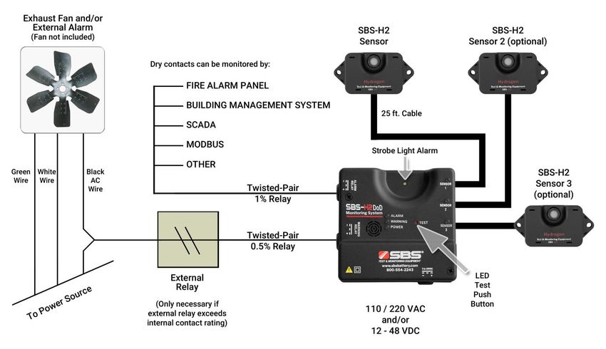
Warnings
This detector is added protection, not a substitute for prudent safety measures, for
where hydrogen gas may be present.
For large or highly-sensitive areas, Exponential Power, Inc. recommends installing
additional sensors for increased coverage area.
The hydrogen sensor does not provide protection from fires or hydrogen explosions.
The relay contacts are intended to be connected to a safety system that would enable
audible alarms, system shutdown and ventilation.
Ensure that installation complies completely with all relevant Local, State, Federal and
OSHA safety and health regulations.
If a sensor enters warning or alarm mode there is a risk of combustion or explosion. To
avoid injury, leave the area immediately.
The sensor is calibrated for operation in air. Tampering with the sensor or operation in
environments that are exposed to other types of gases can lead to inaccurate
readings, false alarms or permanent damage.
Please see troubleshooting guide for list of gases and compounds that may damage or
alter a sensor’s performance.
Uncured silicone compounds or extended exposure to silicone off gassing can give
inaccurate readings or false alarms on a sensor.
SBS-H2 Users Manual, Rev. 03-21-TNEMDH2 Page 2 March 2021
Table of Contents
 Description                              Page      Section
  Overview                                   5        1.0
  Benefits                                   5        2.0
  How It Works                               5        3.0
  Specifications                             6        4.0
  Sensor                                     7        5.0
  Main Control                               7        6.0
  Installation                            8 - 11      7.0
  Operation                                 12        8.0
  Electrical Testing                        13        9.0
  Testing the Sensor                        13       10.0
  Troubleshooting/Maintenance             14 - 15    11.0

SBS-H2 Users Manual, Rev. 03-21-TNEMDH2    Page 3             March 2021

Main Unit and Accessories
Part No. Description
Hydrogen Gas Detector
SBS-H2-DoD
Includes: one (1) main control, one (1) H2-SENSOR and one (1) 25 ft. cable
H2-JB Junction Box with Knockouts, 4 11/16" X 4 11/16", Metal
H2-SENSOR Hydrogen Gas Sensor Only (No Cable)
H2-SENSOR-25FT Additional/Replacement Hydrogen Gas Sensor with 25 ft. Cable
H2-SENSOR-50FT Additional/Replacement Hydrogen Gas Sensor with 50 ft. Cable
H2-SENSOR-100FT Additional/Replacement Hydrogen Gas Sensor with 100 ft. Cable
Field Test Kit for SBS-H2
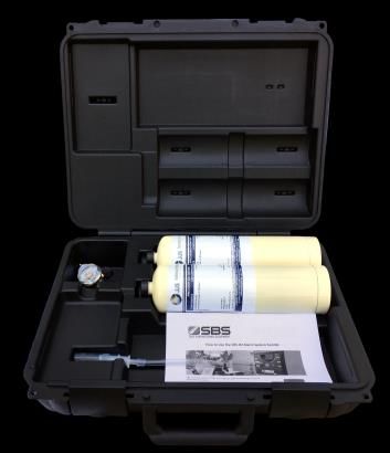
H2-DoD-TESTKIT
Includes: case, regulator, tubing and two (2) cylinders of H2 gas (0.5% and 1%)
Field Test Kit for SBS-H2
H2-TESTKIT-INTL
Includes: case, regulator and tubing – does not include H2 gas cylinders
E190399 110Vac 3 Prong AC Cord, 10 Ft., 18-3 AWG
SBS-H2 Users Manual, Rev. 03-21-TNEMDH2 Page 4 March 2021
1.0 Overview
Batteries on charge emit hydrogen gas as part of the chemical reaction of recharge.
Concentrations of 4.1% to 75% H2 mixed with air can be explosive. Sparks or hot surfaces can
ignite hydrogen gas.

The SBS-H2-DoD hydrogen detector acts as a monitor and provides a visual and audible alarm when
hydrogen is detected. The unit also has a 0.5% concentration relay that can trigger exhaust fan
operation and a 1.0% concentration relay that can trigger a building management/alarm system (via
dry contact) before the gas reaches the lower explosive limit (LEL) of 4.1%.

*The design of this unit has been built to meet the maximum allowable gas concentration levels allowed in the
Department of Defense Specification UFC 3-520-05 Section 3-5.1 when integrated Battery Exhaust System.

2.0 Benefits
In addition to protecting employees and property, the detector may also reduce the following costs:

Energy Efficiencies
Instead of continuously running an exhaust fan to prevent hydrogen gas accumulation, use the
detector to activate a fan only if the gas concentration reaches 0.5%.

Insurance Savings
Installation of a detector in areas where batteries are charged may result in a premium reduction.

3.0 How it Works
Should the concentration of hydrogen gas in the air surrounding the sensor reach 0.5% by volume,
the “0.5% Warning” yellow LED will light up on the main control of the unit. In addition, the 0.5%
internal relay will de-energize and can be used to activate a remote exhaust fan.

Should the hydrogen gas concentration reach 1.0% by volume, the “1% Alarm” red LED will light up,
the strobe will flash and an audible alarm will sound. In addition, the 1% internal relay will de-energize
and can be used to activate a building management/alarm system (via SCADA/Modbus).

The SBS-H2 provides automatic operation, continuous detection, high sensitivity, stability and solid-
state reliability. The unit uses 120/240 Vac 50/60 Hz and/or 12 - 48 Vdc operating voltages.

SBS-H2 Users Manual, Rev. 03-21-TNEMDH2               Page 5                                        March 2021
4.0 Specifications
Dimensions
Main control: 4.7" L x 4.7" W x 1.2" D
Sensor: 3.1" L x 1.6" W x 0.87" D
Mounting
Wall: two 3/16" screws (not included)
H2-JB Junction box: 4 11/16" x 4 11/16" 2-gang junction box
Power Requirements/Options
Warning: Power requirements for the unit and relays should not exceed min/max specifications
120 Vac, 50/60 Hz Nominal (Terminal J8)
o 93 - 121 Vac
o 250mA / 10W Max
220 Vac, 50/60 Hz Nominal (Terminal J8)
o 185 - 242 Vac
o 125mA / 10W Max
12-48 Vdc Nominal (Terminal J9)
o 9 - 58 Vdc
o 600mA / 6W Max
o Note: An earth ground must be supplied to the GND terminal on the AC terminal block
when using only the DC power supply
Relays
0.5% Warning Relay (Terminal J6) “Fail Safe Mode of Operation”
o 1 Normally Open and 1 Normally Closed contact
o Rated for 15 A resistive @ 120 Vac
o Rated for 10 A resistive @ 277 Vac
o Rated for 10 A resistive @ 28 Vdc
1.0% Alarm Relay (Terminal J3) “Fail Safe Mode of Operation”
o 1 Normally Open and 1 Normally Closed contact
o Rated for 0.5A @ 28 Vdc
Temperature/Humidity
Operating Temperature Range: 32°F (0°C) to 122°F (50°C)
Operating Humidity Range: 20-95% non-condensing
Storage Humidity Range: 5-95% non-condensing
Maximum Altitude
2000 meters
Audible Alarm
85 dB at 10’ @ 1.6 - 3.2 KHz
Strobe LED
146 lumens at 1A @ 3.2-4.2V
SBS-H2 Users Manual, Rev. 03-21-TNEMDH2 Page 6 March 2021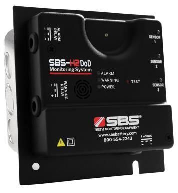
5.0 Sensor
The H2-SENSOR consists of an electronic sensing element whose electrical conductivity increases
when hydrogen is detected at its surface. Conductivity of the sensor is proportional to the gas
concentration, which is continuously monitored by the electronic alarm circuits.

The sensor only monitors for hydrogen gas (H2) and will not alarm for Hydrogen Sulfide (H2S), which
has an odor at very low concentrations.

                              Sensor Head

           Hydrogen Sensor                                               Cat5 Cable
                                                              (25 ft. std., 50/100 ft. optional)

6.0 Main Control
                                          Strobe Alarm
                                                            Main Control Indicators (3 LEDs)

                                                               Individual Sensor Indicators

                                                                (For troubleshooting, refer
                                                                to page 14.)

                           Main Control

SBS-H2 Users Manual, Rev. 03-21-TNEMDH2            Page 7                                  March 2021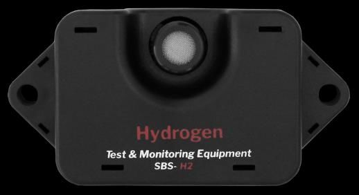
7.0 Installation
          WARNING
AC voltage relay terminals (120/240 Vac) are located within this detector, presenting a hazard to
service technicians. Only qualified technicians should open the detector case and service the internal
circuits. Ensure power is removed from the detector relays prior to servicing the unit. Failure to do so
may result in injury or death.

Mounting and Power Options

                                                      Wall Mountable
                                                      Integrated back mounting plate allows user
                                                      to easily mount directly to any wall using
                                                      3/16" screws (not included).

                                                      Wiring
                                                      Power and alarm wires can run through the
                                                      sides of the unit.
Alarm Wiring

                                                Input Power

                                                      H2-JB Junction Box Mountable (optional)
                                                      Mounts to a standard, 4 11/16" x 4 11/16"
                                                      2-gang junction box

                                                      Hardwire Option
                                                      Run AC and/or DC power and alarm wires
                                                      through back of the unit, into the gang box and
                                                      out through conduit.

                                                      E190399 AC Line Cord
                                                      3-prong grounded AC cord, 18-3 AWG

SBS-H2 Users Manual, Rev. 03-21-TNEMDH2          Page 8                                    March 2021
Mounting Location
Hydrogen is colorless and odorless; the lightest of all gases, and thus rises. The sensor should be
installed at the highest, draft-free location in the battery room, cabinet or compartment where
hydrogen gas would accumulate.
The detector measures hydrogen gas concentration in the air immediately surrounding the sensor.
The area one sensor will monitor depends on the properties of the battery compartment or room.
Hydrogen gas may accumulate in several areas of the battery compartment or room and multiple
sensors/detectors may be necessary.
The main control can be mounted wherever is convenient for the user, but should be within the cable
length range to connect to each sensor.
The sensor should be mounted at the highest, draft-free location in the battery room, cabinet or
compartment. Each sensor connects with the main control via the cable.
Carefully remove the main control cover by removing the two screws located on the front of the cover.
Attach the main control to the wall, ceiling or optional junction box using the mounting holes at the top
and bottom of the main control’s mounting plate.
After the power and relay wiring is complete, connect each cable from main control to each sensor
and refasten the main control cover.
Power Options
The detector has terminal blocks for connections to a single-phase 120/240 Vac 50/60 Hz power
source (Terminal J8), and/or a 12-48 Vdc power source (Terminal J9). The power supply inputs are
redundant, so the unit can use the DC input as a backup source.
Relays
The detector has two (2) internal alarm relays:
0.5% warning relay (Terminal J6) is activated when a sensor detects 0.5% concentration of
hydrogen gas. The 0.5% relay’s dry contacts are rated at 10A/250 Vac, sufficient for most 1/3
HP exhaust fans.
1% alarm relay (Terminal J3) is activated when a sensor detects 1% concentration of
hydrogen gas. The 1% relay’s dry contacts are rated for 0.5A/28 Vdc.
Note: For higher current requirements, add an external relay.
Mounting Options
Junction Box Mounted
For 120/240 Vac power, use 18-3 gauge stranded wire.
For 9 - 58 Vdc power, use 18-2 conductor insulated wire.
For relay wires, use stranded wire. Maximum wire size for connector terminations is 14 AWG.
Stranded conductors must be terminated in a manner to prevent shorting from one terminal to another
by a loose strand. Tin the wires with solder if required.
Wall Mounted
For 120 Vac power, an 18-3 gauge insulated line cord is required.
For 9 - 58 Vdc power, use 18-2 conductor insulated cable from the DC supply.
For relay wires, use stranded wire. Maximum wire size for connector terminations is 14 AWG.
SBS-H2 Users Manual, Rev. 03-21-TNEMDH2 Page 9 March 2021Exponential Power, Inc. supplies a tie-wrap to
secure the AC mains’ wiring. The tie wrap can
rotate up to 270 degrees to accommodate your
installation.
Disconnection of Supplying Power
When the unit is hard wired, an external 10 Amp (minimum) circuit-breaker or switch should be
installed to act as a disconnecting device. The circuit-breaker must open all supply conductors
simultaneously, be easily reached by operators and be marked as the disconnecting device for the
equipment.
For Installation of Additional Sensors
A maximum of three (3) sensors may be connected to each main control. Multiple detectors and
sensors can be installed to meet the space coverage requirements of your particular installation.
Locate the additional sensors’ installation points within cable reach of the main control and mount the
sensor. Connect the cables from any additional sensors to the Sensor 2 and Sensor 3 inputs on the
main control.
SBS-H2 Users Manual, Rev. 03-21-TNEMDH2 Page 10 March 2021Alarm System Electronics
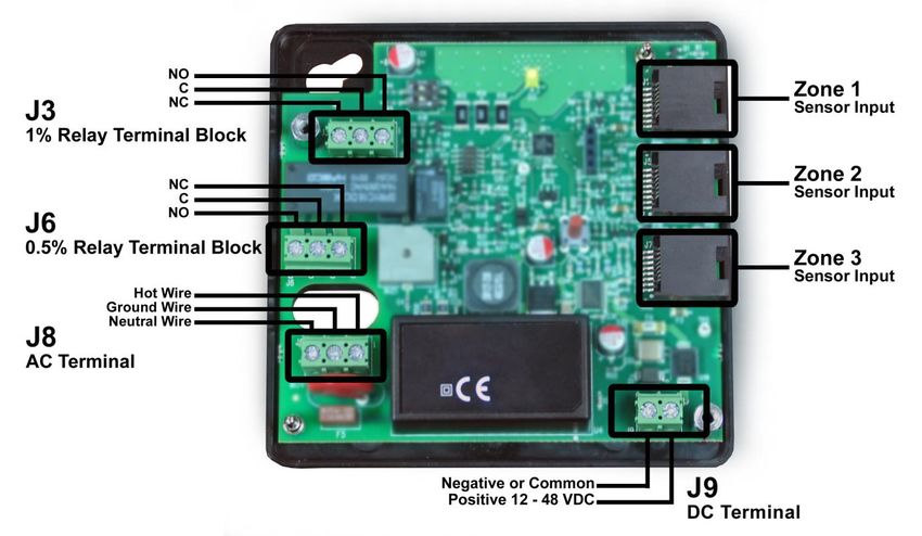
Please refer to the illustration below to identify proper power and relay connection points in the
detector. It is advisable to use a pair of 14 gauge or smaller stranded wire for the relay contacts to
help reduce any interference within the area that may cause false alarms.
Each of the Cat5 sensor input connections has a status indicator LED on the main control, which will
illuminate solid green when a sensor is connected and operating normally. A sensor’s corresponding
LED will flash at the same rate as the strobe LED when detecting 0.5% or 1% H2 concentration. The
LED for a sensor that is in alarm mode will flash at the same rate as the strobe LED. The alarming
sensor and strobe LED will flash at a faster rate than the LED for a sensor that is only in warning
mode.
Terminal Connection Diagram
Using the Mechanical Relays
1. Remove the front cover of the main control by removing two fix screws and pulling straight off
the body. This will reveal the inner electronics of the alarm box.
2. Locate the terminal blocks for the relays and determine which condition you would like the
relay to be related to. Use the 0.5% relay (Terminal J6) for the warning condition and the 1%
relay (Terminal J3) for the alarm condition.
3. Replace the front cover on the alarm box.
SBS-H2 Users Manual, Rev. 03-21-TNEMDH2 Page 11 March 20218.0 Operation
Keep the detector on at all times. The solid green LED for ‘POWER’ on the main control indicates that
the detector is powered on.
When power is first turned on, the 0.5% and 1.0% relays will energize switching the positions
of the contacts, a warm up period of 30 seconds will elapse before the unit will function. This
delay is to prevent false activation of the internal relays and alarm.
Should the concentration of hydrogen gas in the air surrounding the sensor reach 0.5% by volume,
the “0.5% Warning” yellow LED will light up on the main control of the unit. In addition, the 0.5%
internal relay will de-energize and can be used to activate a remote exhaust fan.
Should the hydrogen gas concentration reach 1.0% by volume, the “1% Alarm” red LED will light up,
the strobe will flash and an audible alarm will sound. In addition, the 1% internal relay will de-energize
and can be used to activate a building management/alarm system (via dry contacts).
Main Control Indicators
Individual Sensor Indicators
Main Control Individual Sensor Relay Audible
Condition Indicators Strobe
Indicators Closure Alarm
Power Warning Alarm
Normal Operation Energized None None
(sensor installed)
Warning Relay
H2 Warning (0.5% H2) None None
De-Energized
(blinking green)
Warning and
H2 Alarm (1% H2) Alarm Relay ON ON
(same flash rate as strobe) De-Energized
Sensor/Cable Fault N/A None None
Communication with
N/A None None
Sensor Lost
(plugged in, but not lit)
SBS-H2 Users Manual, Rev. 03-21-TNEMDH2 Page 12 March 20219.0 Electrical Testing
A "TEST" button is located on the front of the main control. Push and hold this button for
approximately 10 seconds to test the unit's electronic circuitry.
The warning and alarm LEDs will light up in sequence, the strobe will flash, the relays will activate
whatever is connected to them and the internal warning alarm will sound.
Note: The "TEST" button does NOT test the sensor(s) itself – only the unit’s electronic circuitry.
10.0 Testing the Sensor
The sensors and main controls are factory calibrated. It is recommended to test each sensor’s
functionality every 12-18 months with the H2-DoD TESTKIT.
The H2-TESTKIT is intended for periodic testing of the functionality and proper operation of the
system. Once a sensor is installed, calibration or adjustment of the sensor is not possible. Please
contact your sales representative if sensor calibration is desired or required.
The H2-DoD TESTKIT includes the following:
0.5% (17 liters) H₂ in air calibrated gas canister
1.0% (17 liters) H₂ in air calibrated gas canister
Regulator
Flexible tubing with sensor head adapter
Testing the 0.5% Warning and 1.0% Alarm State
1. Connect the calibration fixture to the 0.5% H2 air gas cylinder.
2. Secure the test fixture to the sensor module connected to sensor by pressing the flexible tubing
completely over the inlet to the sensor head.
3. Turn on the gas flow by fully opening the valve on the cylinder regulator to allow gas to flow.
Please wait 30 seconds to ensure the air in the tubing has been purged.
4. Continue gas flow and wait for the yellow LED warning to light up and the 0.5% relay to
energize.
5. Turn off gas and remove from sensor.
6. Repeat Steps 1-5 above using the 1% H2 air gas cylinder to activate the 1% alarm and relay.
The 1% alarm threshold is connected to the red LED, the audible alarm and the strobe light up,
which will activate during testing.
7. Repeat steps for every sensor installed.
Note: If the unit does not alarm during these tests the sensor may need to be replaced.
Replacing the Sensor
In a typical operating environment Exponential Power, Inc. recommends that each sensor be replaced
every three years. An abusive operating environment can and will shorten a unit’s useful life. In
dusty/dirty applications or in situations where a sensor is often subjected to different gases, it is
recommended to replace each sensor after one (1) year.
SBS-H2 Users Manual, Rev. 03-21-TNEMDH2 Page 13 March 202111.0 Troubleshooting and Maintenance No Power Verify the AC and/or DC power cables are installed per the connection diagram on page 11. Relays The SBS-H2 system was designed for the relays to operate in a failsafe condition when the power supply is interrupted. If the fan connected to a relay runs as soon as the unit is powered on, the unit has been wired for the use of the Normally Open contact instead of a Normally Closed contact. False Alarms Each sensor has been calibrated for the detection of hydrogen gas, however any combustible gas that comes in contact with a sensor has the potential to activate the warning and/or alarm relays. Contact with any individual or combination of the following gases could trigger false alarms and/or contaminate a sensor. Gases include but are not limited to: - Acetone - Ethyl Ether - Methyl Ethyl Ketone - Acetylene - Ethyl Oxide - Nitric Oxide - Ammonia - Gasoline - Nitric Dioxide - Benzene - Heptane - Propane - Butane - Hexane - Propylene Oxide - n-Butyl Acetate - Hydrogen - Styrene - Carbon Dioxide - Hydrogen Cyanide - Sulfur Dioxide - Carbon Monoxide - Hydrogen Sulfide - Toluene - Ethane - Isopropyl Alcohol - Turpentine - Ethanol - Methane - Vinyl Acetate - Ethyl Acetate - Methanol - Xylene If a sensor’s warning or alarm condition is reached, ventilate the area with clean air. This should reduce the concentration of most gases and the warning or alarm condition should clear. Note: when a warning occurs at 0.5%, the warning will not clear until concentrations drop below 0.3%. Similarly, when an alarm occurs at 1%, the alarm will not clear until concentrations drop below 0.6%. Avoid installation in highly corrosive environments where high densities of hydrogen sulfide, sulfur oxide, chlorine, hydrogen chloride, etc. may be present. These gases can cause corrosion of the element and the power leads to the circuit board. A sensor’s output characteristics can be affected if the sensor becomes contaminated or exposed to heavy alkaline metals. A sensor cannot operate in a zero or low oxygen content atmosphere. If a sensor collects water condensation, its characteristics may temporarily drift. However, light levels of condensation under normal indoor use should not pose a significant problem with performance. Storage The longer a sensor is stored prior to being energized, the longer the warm up and stabilization period may become. Storage Humidity Range: 5 - 95% non-condensing. SBS-H2 Users Manual, Rev. 03-21-TNEMDH2 Page 14 March 2021
Maintenance Tips
To maintain the unit, it is recommended to:
    1.        Test the detector once a month by pressing the ‘TEST’ button.
    2.        Vacuum the alarm cover once a month to remove accumulated dust.
    3.        Never use detergents or solvents to clean the unit or sensor. Chemicals can permanently
              damage or temporarily contaminate a sensor.
    4.        Avoid spraying air fresheners, hair spray, paint or other aerosols near a sensor.
    5.        Never paint the unit or sensor. Paint will seal the vents and interfere with proper sensor
              operation.

WARNINGS
Do not disassemble unit or attempt to repair or modify any component of this instrument. This instrument contains
no user serviceable parts, and substitution of components may impair intrinsic safety, which may adversely affect
product performance and result in injury

The SBS-H2 Hydrogen Alarm System is not a standalone safety device and does not provide protection from hydrogen
explosions. The relay contacts are intended to be connected to a safety system, enabling audible alarms, system shutdown,
ventilation, or other measures to ensure monitoring of hydrogen gas occurs before concentrations reach dangerous levels.

The information in this sheet has been carefully reviewed and is believed to be accurate; however, no responsibility is
assumed for inaccuracies. Exponential Power, Inc. reserves the right to make changes without further notice to any product,
datasheet, technical data bulletin, or website.

Exponential Power, Inc. makes no warranty, representation of guarantee regarding the suitability of its product for any
particular purpose, nor does Exponential Power, Inc. assume any liability arising out of the application or use of any product
and specifically disclaims any and all liability, including without limitation consequential or incidental damages. “Typical”
parameters can and do vary in different applications. All operating parameters, including “Typical” must be validated for each
customer application by customer’s technical experts.

Exponential Power, Inc. products are not designed, intended, or authorized for use in any application in which the failure of the
Exponential Power, Inc. product could create a situation where personal injury or death may occur.

Should buyer purchase or use Exponential Power, Inc. products for any such unintended or unauthorized application, Buyer
shall indemnify and hold Exponential Power, Inc. and its officers, employees, subsidiaries, affiliates, and distributors harmless
against all claims, costs, damages, and expenses, and reasonable attorney fees arising out of, directly or indirectly, any claim
of personal injury or death associated with such unintended or unauthorized use, even if claim alleges that Exponential Power,
Inc. was negligent regarding the design or manufacture of the part.

In the case of a defect in the sensor, Exponential Power, Inc. shall not be liable for any damages which may result, including,
but not limited to, loss of revenue, property, or life. In an event, Exponential Power, Inc. shall limit liability to replacement of
the defective unit. Exponential Power, Inc. does not convey any license under its patent rights nor the rights of others.

SBS-H2 Users Manual, Rev. 03-21-TNEMDH2                       Page 15                                             March 2021
N56 W16665 Ridgewood Dr. www.exponentialpower.com Menomonee Falls, WI 53051 1.800.554.2243 SBS-H2 Users Manual, Rev. 03-21-TNEMDH2 Page 16 March 2021
You can also read