Quick Start Preparing Tools and Components phone or tablet. You may have even link to the URL by scanning the QR code - Geizhals Static Content
←
→
Page content transcription
If your browser does not render page correctly, please read the page content below
Quick Start
Thank you for purchasing the MSI® MAG X570S TOMAHAWK MAX WIFI/ MAG X570S
TORPEDO MAX motherboard. This Quick Start section provides demonstration
diagrams about how to install your computer. Some of the installations also provide
video demonstrations. Please link to the URL to watch it with the web browser on your
phone or tablet. You may have even link to the URL by scanning the QR code.

Preparing Tools and Components

     AMD® AM4 CPU

                                        CPU Fan
                                                                        Chassis

       DDR4 Memory

                                 Power Supply Unit
                                                                   Graphics Card

   Thermal Paste

                              SATA Hard Disk Drive
                                                                 SATA DVD Drive

      Phillips Screwdriver                        A Package of Screws

                                                                            Quick Start   1
Safety Information
∙∙ The components included in this package are prone to damage from electrostatic
discharge (ESD). Please adhere to the following instructions to ensure successful
computer assembly.
∙∙ Ensure that all components are securely connected. Loose connections may cause
the computer to not recognize a component or fail to start.
∙∙ Hold the motherboard by the edges to avoid touching sensitive components.
∙∙ It is recommended to wear an electrostatic discharge (ESD) wrist strap when
handling the motherboard to prevent electrostatic damage. If an ESD wrist strap is
not available, discharge yourself of static electricity by touching another metal object
before handling the motherboard.
∙∙ Store the motherboard in an electrostatic shielding container or on an anti-static
pad whenever the motherboard is not installed.
∙∙ Before turning on the computer, ensure that there are no loose screws or metal
components on the motherboard or anywhere within the computer case.
∙∙ Do not boot the computer before installation is completed. This could cause
permanent damage to the components as well as injury to the user.
∙∙ If you need help during any installation step, please consult a certified computer
technician.
∙∙ Always turn off the power supply and unplug the power cord from the power outlet
before installing or removing any computer component.
∙∙ Keep this user guide for future reference.
∙∙ Keep this motherboard away from humidity.
∙∙ Make sure that your electrical outlet provides the same voltage as is indicated on
the PSU, before connecting the PSU to the electrical outlet.
∙∙ Place the power cord such a way that people can not step on it. Do not place
anything over the power cord.
∙∙ All cautions and warnings on the motherboard should be noted.
∙∙ If any of the following situations arises, get the motherboard checked by service
personnel:
▪▪Liquid has penetrated into the computer.
▪▪The motherboard has been exposed to moisture.
▪▪The motherboard does not work well or you can not get it work according to user
guide.
▪▪The motherboard has been dropped and damaged.
▪▪The motherboard has obvious sign of breakage.
∙∙ Do not leave this motherboard in an environment above 60°C (140°F), it may damage
the motherboard.
2 Quick StartCase stand-off notification
To prevent damage to the motherboard, any unnecessary mounting stand-off between
the motherboard circuits and the computer case is prohibited. The Case standoff keep
out zone signs will be marked on the backside of motherboard (as shown below) to
serve as a warning to user.
Avoid collision notification
Protective paint is printed around each screw hole to prevent parts from being
scratched.
Quick Start 3Installing a Processor
https://youtu.be/Xv89nhFk1vc
1
3
2
5
4
8
6
9
7
4 Quick Start⚠⚠Important
If you are installing the screw-type CPU heatsink, please follow the figure below to
remove the retention module first and then install the heatsink.
1
3
2
Quick Start 5Installing DDR4 memory
http://youtu.be/T03aDrJPyQs
DIMMA1
DIMMA2 DIMMA2 DIMMA2
DIMMB2 DIMMB1
DIMMB2
6 Quick StartConnecting the Front Panel Header
http://youtu.be/DPELIdVNZUI
-
LED
ER W
+ PO
ED
RL E
OW P
ED
DL
W
HD
RS
WE
PO
W
TS
SE
RE
Power LED Power Switch
+
+
2 10
-
-
JFP1
RESET SW
1 9
Reserved
HDD LED
+
+
-
-
HDD LED Reset Switch
1 HDD LED + 2 Power LED +
3 HDD LED - 4 Power LED -
5 Reset Switch 6 Power Switch
7 Reset Switch 8 Power Switch JFP1
9 Reserved 10 No Pin
HDD LED -
HDD LED
HDD LED +
POWER LED -
POWER LED
POWER LED +
Quick Start 7Installing the Motherboard
1
⚽⚽
https://youtu.be/wWI6Qt51Wnc
Torque:
3 kgf·cm*
2
BAT1
*3 kgf·cm
= 0.3 N·m
= 2.6 lbf·in
8 Quick StartConnecting the Power Connectors
http://youtu.be/gkDYyR_83I4
ATX_PWR1 CPU_PWR1
CPU_PWR2
Quick Start 9Installing SATA Drives
http://youtu.be/RZsMpqxythc
1
2
3
5
4
10 Quick StartInstalling a Graphics Card
http://youtu.be/mG0GZpr9w_A
1
3 2
5
4
6
Quick Start 11Connecting Peripheral Devices
∙∙ MAG X570S TOMAHAWK MAX WIFI
Proc
esso
r wit
h int
egra
ted g
raph
ics
12 Quick Start∙∙ MAG X570S TORPEDO MAX
Proc
esso
r wit
h int
egra
ted g
raph
ics
Quick Start 13Power On
1 2
3
4
14 Quick StartContents
Quick Start ............................................................................................................. 1
Preparing Tools and Components .......................................................................... 1
Safety Information .................................................................................................. 2
Case stand-off notification ..................................................................................... 3
Avoid collision notification ...................................................................................... 3
Installing a Processor ............................................................................................. 4
Installing DDR4 memory ........................................................................................ 6
Connecting the Front Panel Header ....................................................................... 7
Installing the Motherboard ..................................................................................... 8
Connecting the Power Connectors......................................................................... 9
Installing SATA Drives........................................................................................... 10
Installing a Graphics Card .................................................................................... 11
Connecting Peripheral Devices ............................................................................ 12
Power On............................................................................................................... 14
Specifications....................................................................................................... 17
Package contents ................................................................................................ 24
Block Diagram .................................................................................................... 25
Rear I/O Panel...................................................................................................... 26
LAN Port LED Status Table................................................................................... 27
Audio Ports Configuration .................................................................................... 27
Realtek Audio Console ......................................................................................... 28
Overview of Components .................................................................................... 31
CPU Socket ........................................................................................................... 33
DIMM Slots............................................................................................................ 34
PCI_E1~4: PCIe Expansion Slots .......................................................................... 35
M2_1~2: M.2 Slots (Key M) ................................................................................... 36
SATA1~6: SATA 6Gb/s Connectors ....................................................................... 38
JFP1, JFP2: Front Panel Connectors ................................................................... 38
CPU_PWR1~2, ATX_PWR1: Power Connectors ................................................... 39
CPU_FAN1, PUMP_FAN1, SYS_FAN1~4: Fan Connectors ................................... 40
JUSB1~2: USB 2.0 Connectors ............................................................................. 41
JUSB3~4: USB 3.2 Gen 1 5Gbps Connectors ....................................................... 41
JUSB5: USB 3.2 Gen 2 10Gbps Type-C Connector ............................................... 42
JAUD1: Front Audio Connector ............................................................................ 42
JCI1: Chassis Intrusion Connector ....................................................................... 43
JTPM1: TPM Module Connector ........................................................................... 43
JCOM1: Serial Port Connector ............................................................................. 44
Contents 15JBAT1: Clear CMOS (Reset BIOS) Jumper ........................................................... 44
JPWRLED1: LED power input............................................................................... 45
EZ Debug LED ....................................................................................................... 45
JRGB1~2: RGB LED connectors ........................................................................... 46
JRAINBOW1~2: Addressable RGB LED connectors ............................................. 47
Installing OS, Drivers & MSI Center .................................................................... 48
Installing Windows® 10 ....................................................................................... 48
Installing Drivers .................................................................................................. 48
MSI Center ............................................................................................................ 48
UEFI BIOS............................................................................................................. 49
BIOS Setup ........................................................................................................... 50
Entering BIOS Setup ............................................................................................. 50
BIOS User Guide ................................................................................................... 50
Resetting BIOS...................................................................................................... 51
Updating BIOS....................................................................................................... 51
RAID Configuration .............................................................................................. 53
Troubleshooting .................................................................................................. 54
16 ContentsSpecifications
∙∙ Supports AMD Ryzen™ 5000 Series, 5000 G-Series, 4000
G-Series, 3000 Series, 3000 G-Series, 2000 Series and 2000
G-Series desktop processors*
CPU
∙∙ Supports Socket AM4
* Please go to msi.com to get the newest support status as new processors are
released.
Chipset AMD X570 Chipset
∙∙ 4x DDR4 memory slots, support up to 128GB
∙∙ Supports 1866/ 2133/ 2400/ 2667/ 2800/ 2933/ 3000/ 3066/
3200 MHz by JEDEC*
∙∙ Max overclocking frequency by A-XMP OC mode:
▪▪For Ryzen™ 5000 G-Series & 4000 G-Series
processors
▫▫1DPC 1R Max speed up to 5100 MHz
▫▫1DPC 2R Max speed up to 4000 MHz
▫▫2DPC 1R Max speed up to 4266 MHz
Memory ▫▫2DPC 2R Max speed up to 3600 MHz
▪▪For Ryzen™ 5000 Series & 3000 Series processors
▫▫1DPC 1R Max speed up to 5100 MHz
▫▫1DPC 2R Max speed up to 3866 MHz
▫▫2DPC 1R Max speed up to 4000 MHz
▫▫2DPC 2R Max speed up to 3600 MHz
∙∙ Supports Dual-Channel mode
∙∙ Supports non-ECC, un-buffered memory
*Please refer to www.msi.com for more information on compatible memory.
∙∙ Supports PCIe 4.0 / PCIe 3.0
▪▪PCIe 4.0 is available only on AMD Ryzen™ 5000 Series
and 3000 Series desktop processors
∙∙ 1x PCIe x16 slot (From processor)
▪▪PCI_E1 supports PCIe 4.0/ 3.0 x16
Expansion Slot
▪▪PCI_E1 supports PCIe 3.0 x8 on AMD Ryzen™ 3000 G-
and 2000 G- series desktop processors
∙∙ 1x PCIe x16 slot (From X570 chipset)
▪▪PCI_E3 supports PCIe 4.0/ 3.0 x4
∙∙ 2x PCIe 3.0 x1 slots (From X570 chipset)
Continued on next page
Specifications 17Continued from previous page
∙∙ 1x HDMI 2.1 port, supports a maximum resolution of 4K
60Hz*/**
Onboard Graphics
*Available only on processors featuring integrated graphics.
** Graphics specifications may vary depending on the CPU installed.
Multi-GPU Supports AMD CrossFire™ Technology
1x Realtek® 8125B 2.5Gbps LAN Controller
LAN 1x Realtek® RTL8111H 1Gbps LAN Controller (For MAG
X570S TORPEDO MAX)
Intel® Wi-Fi 6E AX210
∙∙ The Wireless module is pre-installed in the M.2 (Key-E)
slot
Wireless LAN ∙∙ Supports MU-MIMO TX/RX, 2.4GHz/ 5GHz/ 6GHz*
& Bluetooth® (160MHz) up to 2.4Gbps
(For MAG X570S
TOMAHAWK MAX ∙∙ Supports 802.11 a/ b/ g/ n/ ac/ ax
WIFI)
∙∙ Supports Bluetooth® 5.2**, FIPS, FISMA
* Wi-Fi 6E 6GHz may depend on every country’s regulations and will be ready in
WIN10 21H1.
** Bluetooth 5.2 will be ready in WIN10 21H1.
∙∙ 6x SATA 6Gb/s ports (from AMD X570 Chipset)
∙∙ 2x M.2 slots (Key M)
▪▪Supports PCIe 4.0 / PCIe 3.0
▪▪PCIe 4.0 is available only on AMD Ryzen™ 5000 Series
and 3000 Series desktop processors
Storage
▪▪Supports up to SATA 6Gb/s
▪▪M2_1 slot (from Processor)
▫▫Support 2280/22110 storage devices
▪▪M2_2 slot (from AMD X570 Chipset)
▫▫ Supports 2242/ 2260/ 2280 storage devices
RAID ∙∙ Supports RAID 0, RAID 1 and RAID 10
∙∙ Realtek® ALC4080 Codec
Audio ▪▪7.1-Channel High Definition Audio
▪▪Supports S/PDIF output
I/O Controller NUVOTON NCT6797D Controller Chip
Continued on next page
18 SpecificationsContinued from previous page
∙∙ CPU/ System/ Chipset temperature detection
Hardware Monitor ∙∙ CPU/ System/ Pump fan speed detection
∙∙ CPU/ System/ Pump fan speed control
AMD X570 Chipset
∙∙ 3x USB 3.2 Gen 2 10Gbps ports (2 Type-A ports on the
back panel, 1 Type-C internal connector)
∙∙ 4x USB 3.2 Gen 1 5Gbps ports available through the
internal USB 3.2 Gen 1 5Gbps connectors
∙∙ 1x USB 2.0 port on the back panel
USB USB 2.0 Hub
∙∙ 5x USB 2.0 ports (1 Type-A port on the back panel, 4 ports
available through the internal USB 2.0 connectors)
AMD Processor
∙∙ 2x USB 3.2 Gen 2 10Gbps ports on the back panel (Type-A
&Type-C)
∙∙ 2x USB 3.2 Gen 1 5Gbps Type-A ports on the back panel
∙∙ 1x Flash BIOS Button
∙∙ 1x PS/2 keyboard/ mouse combo port
∙∙ 2x USB 2.0 ports
∙∙ 2x Wi-Fi Antenna connectors (For MAG X570S TOMAHAWK
MAX WIFI)
∙∙ 2x USB 3.2 Gen1 5Gbps Type-A ports
Back Panel ∙∙ 1x HDMI port
Connectors
∙∙ 3x USB 3.2 Gen 2 10Gbps Type-A port
∙∙ 1x USB 3.2 Gen 2 10Gbps Type-C port
∙∙ 1x 2.5Gbps LAN port
∙∙ 1x 1Gbps LAN port (For MAG X570S TORPEDO MAX)
∙∙ 5x audio jacks
∙∙ 1x Optical S/PDIF Out connector
Continued on next page
Specifications 19Continued from previous page
∙∙ 1x 24-pin ATX main power connector
∙∙ 1x 8-pin ATX 12V power connector
∙∙ 1x 4-pin ATX 12V power connector
∙∙ 6x SATA 6Gb/s connectors
∙∙ 2x USB 2.0 connectors (supports additional 4 USB 2.0
ports)
∙∙ 2x USB 3.2 Gen 1 5Gbps connectors (supports additional 4
USB 3.2 Gen 1 5Gbps ports)
∙∙ 1x USB 3.2 Gen 2 10Gbps Type-C port
Internal Connectors ∙∙ 1x 4-pin CPU fan connector
∙∙ 1x 4-pin water-pump connector
∙∙ 4x 4-pin system fan connectors
∙∙ 1x Front panel audio connector
∙∙ 2x System panel connectors
∙∙ 1x Chassis Intrusion connector
∙∙ 1x TPM module connector
∙∙ 1x Serial port connector
∙∙ 1x Chassis Intrusion connector
Jumpers ∙∙ 1x Clear CMOS jumper
∙∙ 2x 4-pin RGB LED connectors
∙∙ 2x 3-pin RAINBOW LED connectors
LED Features
∙∙ 4x EZ Debug LED
∙∙ 1X EZ LED Control switch
∙∙ 1x 256 Mb flash
∙∙ UEFI AMI BIOS
BIOS Features
∙∙ ACPI 6.1, SM BIOS 2.8
∙∙ Multi-language
Form Factor ∙∙ ATX Form Factor
∙∙ 12 in. x 9.6 in. (30.5 cm x 24.4 cm)
Continued on next page
20 SpecificationsContinued from previous page
∙∙ Drivers
∙∙ MSI Center
∙∙ CPU-Z MSI GAMING
Software ∙∙ Open Broadcaster Software (OBS)
∙∙ MSI App Player (BlueStacks)
∙∙ Google Chrome™, Google Toolbar, Google Drive
∙∙ Norton™ Internet Security Solution
∙∙ Gaming Mode
∙∙ Smart Priority
∙∙ Game Highlights
∙∙ LAN Manager
∙∙ Mystic Light
∙∙ Ambient Link (For MAG X570S TOMAHAWK MAX WIFI)
∙∙ Frozr AI Cooling
MSI Center
∙∙ User Scenario
Features
∙∙ True Color
∙∙ Live Update
∙∙ Monitor
∙∙ Super Charger
∙∙ Speed Up
∙∙ Smart Image Finder
∙∙ MSI Companion
∙∙ Audio
▪▪Audio Boost 5
∙∙ Network
Special Features
▪▪2.5G LAN
▪▪1G LAN (For MAG X570S TORPEDO MAX)
▪▪Intel WiFi 6E (For MAG X570S TOMAHAWK MAX WIFI)
Continued on next page
Specifications 21Continued from previous page
∙∙ Cooling
▪▪M.2 Shield Frozr
▪▪All Aluminum Design (For MAG X570S TOMAHAWK
MAX WIFI)
▪▪Extended Heatsink Design (For MAG X570S TORPEDO
MAX)
▪▪Pump Fan
▪▪Smart Fan Control
▪▪K7 thermal pad
▪▪Choke pad
∙∙ Storage
▪▪Lightning Gen 4 M.2
▪▪Twin Turbo M.2
∙∙ LED
▪▪Mystic Light
▪▪Mystic Light Extension (RAINBOW/RGB)
Special Features
▪▪Mystic Light SYNC
▪▪Ambient Link (For MAG X570S TOMAHAWK MAX WIFI)
▪▪EZ LED Control
▪▪EZ DEBUG LED
∙∙ Performance
▪▪Lightning Gen 4 PCI-E Slot
▪▪Multi GPU-CrossFire Technology
▪▪DDR4 Boost
▪▪Core Boost
▪▪GAME Boost
▪▪USB with type A+C
▪▪USB 3.2 Gen 2 10G
▪▪Front USB Type-C
▪▪2oz Copper thickened PCB
▪▪Dual CPU Power
Continued on next page
22 SpecificationsContinued from previous page
∙∙ Protection
▪▪PCI-E Steel Armor
▪▪Pre-installed IO shielding
∙∙ Experience
Special Features
▪▪MSI Center
▪▪Frozr AI Cooling
▪▪Click BIOS 5
▪▪Flash BIOS Button
Specifications 23Package contents
Please check the contents of your motherboard package. It should contain:
MAG X570S TOMAHAWK MAX WIFI/ MAG X570S TORPEDO
Motherboard
MAX
Cable SATA 6Gb/s cable 2
Wi-Fi antenna (For MAG X570S TOMAHAWK MAX
1
WIFI)
M.2 screw + standoff (2 sets/pack) 1
Accessories Case badge 1
MAG Sticker 1
Product registration card 1
MSI Reward Program 1
Application DVD USB drive with drivers & utilities 1
User manual 1
Documentation
Quick installation guide 1
Small screwdriver set 1
Gifts
Small brush 1
⚠⚠Important
If any of the above items are damaged or missing, please contact your retailer.
24 Package contentsBlock Diagram
PCI_E1 CPU
PCIe x16
DDR4 2Channel
DIMM A1/A2
DIMM B1/B2
USB 3.2 Gen 2 10Gbps
USB 3.2 Gen 1 5Gbps
M2_1
PCIEx4
PCI_E3
PCIe x4 USB 3.2 Gen 2 10Gbps
Chipset
PCI_E2 USB 3.2 Gen 1 5Gbps
PCI_E4
USB 2.0
M2_2
USB 2.0
Realtek® 8125B Hub
Realtek® RTL8111H (For MAG
X570S TORPEDO MAX) SATA1/2/3/4/5/6
WiFi AX210 (For MAG X570S
TOMAHAWK MAX WIFI) MCU
SPI
TPM
SIO 6797
HD Audio
ALC4080
Block Diagram 25Rear I/O Panel
∙∙ MAG X570S TOMAHAWK MAX WIFI
USB 3.2
Gen1 Audio Ports
PS/2 Mouse/
Keyboard (5Gbps)
Type-A 2.5Gbps LAN
Flash BIOS
Port
Flash BIOS USB 2.0 USB 3.2 Optical
Button Type-A Gen 2 S/PDIF-Out
USB 3.2 (10Gbps)
Wi-Fi Antenna Gen 2 Type-A
connectors (10Gbps)
Type-C
∙∙ MAG X570S TORPEDO MAX
USB 3.2
Gen1 Audio Ports
PS/2 Mouse/ 1Gbps LAN
Keyboard (5Gbps)
Type-A 2.5Gbps LAN
Flash BIOS
Port
USB 2.0 USB 3.2 Optical
Type-A Gen 2 S/PDIF-Out
USB 3.2 (10Gbps)
Flash BIOS Gen 2 Type-A
Button (10Gbps)
Type-C
∙∙ Flash BIOS Port/ Button - Please refer to page 52 for Updating BIOS with Flash BIOS
Button.
26 Rear I/O PanelLAN Port LED Status Table
Link/ Activity LED Speed LED
Status Description Status Description
Off No link Off 10 Mbps connection
Yellow Linked Green 100 Mbps/ 1 Gbps
Blinking Data activity Orange 2.5 Gbps connection
Audio Ports Configuration
Channel
Audio Ports
2 4 6 8
Center/ Subwoofer Out ● ●
Rear Speaker Out ● ● ●
Line-In/ Side Speaker Out ●
Line-Out/ Front Speaker Out ● ● ● ●
Mic In
(●: connected, Blank: empty)
Rear I/O Panel 27Realtek Audio Console
After Realtek Audio Console is installed. You can use it to change sound settings to get
better sound experience.
Application Enhancement
Device
Selection
Main Volume
Connector Settings Jack Status
∙∙ Device Selection - allows you to select a audio output source to change the related
options. The check sign indicates the devices as default.
∙∙ Application Enhancement - the array of options will provide you a complete
guidance of anticipated sound effect for both output and input device.
∙∙ Main Volume - controls the volume or balance the right/left side of the speakers
that you plugged in front or rear panel by adjust the bar.
∙∙ Jack Status - depicts all render and capture devices currently connected with your
computer.
∙∙ Connector Settings - configures the connection settings.
Auto popup dialog
When you plug into a device at an audio jack, a dialogue window will pop up asking you
which device is current connected.
Each jack corresponds to its default setting as shown on the next page.
⚠⚠Important
The pictures above for reference only and may vary from the product you purchased.
28 Rear I/O PanelAudio jacks to headphone and microphone diagram
Audio jacks to stereo speakers diagram
AUDIO INPUT
Audio jacks to 7.1-channel speakers diagram
AUDIO INPUT
Rear Front
Side Center/
Subwoofer
Rear I/O Panel 29Installing antennas
1. Screw the antennas tight to the antenna connectors as shown below.
2. Orient the antennas.
1
2
30 Rear I/O PanelOverview of Components
JRAINBOW2
CPU_PWR2 Processor Socket
JRGB2
CPU_PWR1 CPU_FAN1
PUMP_FAN1
SYS_FAN2
SYS_FAN1
ATX_PWR1
JUSB5
M2_1 DIMMB2
DIMMB1
DIMMA2
DIMMA1
PCI_E1
SATA ▼ 1 ▲ 2
SATA ▼ 3 ▲ 4
PCI_E2 BAT1
SATA ▼ 5 ▲ 6
PCI_E3
JUSB4
M2_2
JCI1
JFP2
PCI_E4
JRAINBOW1
JPWRLED1
JAUD1
JFP1
JRGB1 JBAT1
JTPM1 JUSB3
SYS_FAN3 JUSB2
SYS_FAN4 JUSB1
JCOM1
Overview of Components 31Component Contents
Port Name Port Type Page
CPU_FAN1, PUMP_FAN1,
Fan Connectors 40
SYS_FAN1~4
CPU_PWR1~2, ATX_PWR1 Power Connectors 39
CPU Socket AM4 CPU Socket 33
DIMM Slots Memory slots 34
JAUD1 Front Audio Connector 42
JBAT1 Clear CMOS (Reset BIOS) Jumper 44
JCI1 Chassis Intrusion Connector 43
JCOM1 Serial Port Connector 44
JFP1, JFP2 Front Panel Connectors 38
JPWRLED1 LED power input 45
JRAINBOW1~2 Addressable RGB LED connectors 47
JRGB1~2 RGB LED connectors 46
JTPM1 TPM Module Connector 43
JUSB1~2 USB 2.0 Connectors 41
JUSB3~4 USB 3.2 Gen 1 5Gbps Connectors 41
JUSB5 USB 3.2 Gen 2 10Gbps Type-C Connector 42
M2_1~2 M.2 Slots (Key M) 36
PCI_E1~4 PCIe Expansion Slots 35
SATA1~6 SATA 6Gb/s Connectors 38
32 Overview of ComponentsCPU Socket
Distance from the center of the
CPU to the nearest DIMM slot.
53.5 mm
Introduction to the AM4 CPU
The surface of the AM4 CPU has a
yellow triangle to assist in correctly
lining up the CPU for motherboard
placement. The yellow triangle is
the Pin 1 indicator.
⚠⚠Important
∙∙ When changing the processor, the system configuration could be cleared and reset
BIOS to default values, due to the AM4 processor’s architecture.
∙∙ Always unplug the power cord from the power outlet before installing or removing
the CPU.
∙∙ When installing a CPU, always remember to install a CPU heatsink. A CPU heatsink
is necessary to prevent overheating and maintain system stability.
∙∙ Confirm that the CPU heatsink has formed a tight seal with the CPU before booting
your system.
∙∙ Overheating can seriously damage the CPU and motherboard. Always make sure
the cooling fans work properly to protect the CPU from overheating. Be sure to apply
an even layer of thermal paste (or thermal tape) between the CPU and the heatsink to
enhance heat dissipation.
∙∙ If you purchased a separate CPU and heatsink/ cooler, Please refer to the
documentation in the heatsink/ cooler package for more details about installation.
∙∙ This motherboard is designed to support overclocking. Before attempting to
overclock, please make sure that all other system components can tolerate
overclocking. Any attempt to operate beyond product specifications is not
recommended. MSI® does not guarantee the damages or risks caused by inadequate
operation beyond product specifications.
Overview of Components 33DIMM Slots
DIMMA1 DIMMB1
Channel A Channel B
DIMMA2 DIMMB2
Memory module installation recommendation
DIMMA1
DIMMA2 DIMMA2
DIMMA2
DIMMB1
DIMMB2 DIMMB2
⚠⚠Important
∙∙ Always insert memory modules in the DIMMA2 slot first.
∙∙ To ensure system stability for Dual channel mode, memory modules must be of the
same type, number and density.
∙∙ Some memory may operate at a lower frequency than the marked value when
overclocking due to the memory frequency operates dependent on its Serial Presence
Detect (SPD). Go to BIOS and find the DRAM Frequency to set the memory frequency if
you want to operate the memory at the marked or at a higher frequency.
∙∙ It is recommended to use a more efficient memory cooling system for full DIMMs
installation or overclocking.
∙∙ The stability and compatibility of installed memory module depend on installed CPU
and devices when overclocking.
∙∙ Please refer www.msi.com for more information on compatible memory.
34 Overview of ComponentsPCI_E1~4: PCIe Expansion Slots
PCI_E1: PCIe x16 slot (CPU)
BAT1
PCI_E2: PCIe x1 slot (Chipset)
PCI_E3: PCIe x4 slot (Chipset)
PCI_E4: PCIe x1 slot (Chipset)
AMD Ryzen™ AMD Ryzen™ 5000 AMD Ryzen™ 3000
Slots 5000/ 3000 series G-/ 4000 G-/ 2000 G-/ 2000 G- series
processors series processors processors
PCI_E1 (CPU) PCIe 4.0 x16 PCIe 3.0 x16 PCIe 3.0 x8
PCI_E2 (Chipset) PCIe 3.0 x1 PCIe 3.0 x1 PCIe 3.0 x1
PCI_E3 (Chipset) PCIe 4.0 x4 PCIe 3.0 x4 PCIe 3.0 x4
PCI_E4 (Chipset) PCIe 3.0 x1 PCIe 3.0 x1 PCIe 3.0 x1
⚠⚠Important
∙∙ If you install a large and heavy graphics card, you need to use a tool such as MSI
Gaming Series Graphics Card Bolster to support its weight to prevent deformation of
the slot.
∙∙ For a single PCIe x16 expansion card installation with optimum performance, using
the PCI_E1 slot is recommended.
∙∙ When adding or removing expansion cards, always turn off the power supply and
unplug the power supply power cable from the power outlet. Read the expansion
card’s documentation to check for any necessary additional hardware or software
changes.
Overview of Components 35M2_1~2: M.2 Slots (Key M)
⚽⚽Video Demonstration
Watch the video to learn how to Install
M.2 SSD.
https://youtu.be/2UeWMgjwogU
M2_1 (CPU)
M2_2 (Chipset)
Installing M.2 module
1. Loosen the screws of M.2 SHIELD FROZR heatsink.
2. Remove the M.2 SHIELD FROZR and remove the protective films from the thermal
pads.
2 1
1
1
1
36 Overview of Components3. Secure the supplied M.2 standoff according to your M.2 SSD length if need.
4. Insert your M.2 SSD into the M.2 slot at a 30-degree angle.
5. Secure the M.2 SSD in place with the supplied M.2 8.5H screw.
⚠⚠Important
Skip step 3 and step 5, if you install 22110 M.2 into M2_1 slot or install 2280 M.2 into
M2_2 slot.
4
M.2 screw
30º
5
M.2 standoff
3
heatsink standoff
6. Put the M.2 SHIELD FROZR heatsink back in place and secure it.
6
6
6
6
Overview of Components 37SATA1~6: SATA 6Gb/s Connectors
These connectors are SATA 6Gb/s interface ports. Each connector can connect to one
SATA device.
SATA2
SATA1
SATA4
SATA3
SATA6
SATA5
⚠⚠Important
∙∙ Please do not fold the SATA cable at a 90-degree angle. Data loss may result during
transmission otherwise.
∙∙ SATA cables have identical plugs on either sides of the cable. However, it is
recommended that the flat connector be connected to the motherboard for space
saving purposes.
JFP1, JFP2: Front Panel Connectors
These connectors connect to the switches and LEDs on the front panel.
Power LED Power Switch
+
+
2 10
-
-
JFP1
1 9
Reserved
+
+
-
-
HDD LED Reset Switch
1 HDD LED + 2 Power LED +
3 HDD LED - 4 Power LED -
5 Reset Switch 6 Power Switch
7 Reset Switch 8 Power Switch
9 Reserved 10 No Pin
Buzzer 1 Speaker - 2 Buzzer +
+
-
JFP2 1
Speaker 3 Buzzer - 4 Speaker +
+
-
38 Overview of ComponentsCPU_PWR1~2, ATX_PWR1: Power Connectors
These connectors allow you to connect an ATX power supply.
8 5
CPU_PWR1
4 1
1 Ground 5 +12V
2 Ground 6 +12V
3 Ground 7 +12V
4 Ground 8 +12V
4 3
CPU_PWR2
2 1
1 Ground 3 +12V
2 Ground 4 +12V
1 +3.3V 13 +3.3V
2 +3.3V 14 -12V
3 Ground 15 Ground
12 24 4 +5V 16 PS-ON#
5 Ground 17 Ground
6 +5V 18 Ground
ATX_PWR1
7 Ground 19 Ground
8 PWR OK 20 Res
1 13 9 5VSB 21 +5V
10 +12V 22 +5V
11 +12V 23 +5V
12 +3.3V 24 Ground
⚠⚠Important
Make sure that all the power cables are securely connected to a proper ATX power
supply to ensure stable operation of the motherboard.
Overview of Components 39CPU_FAN1, PUMP_FAN1, SYS_FAN1~4: Fan Connectors
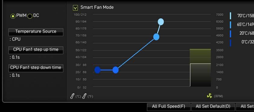
Fan connectors can be classified as PWM (Pulse Width Modulation) Mode or DC Mode.
PWM Mode fan connectors provide constant 12V output and adjust fan speed with
speed control signal. DC Mode fan connectors control fan speed by changing voltage.
You can follow the instruction below to adjust the fan connector to PWM or DC Mode.
CPU_FAN1
PUMP_FAN1
SYS_FAN2
SYS_FAN1
Default Max. Max.
Connector
fan mode current power
CPU_FAN1 Auto mode 2A 24W
PUMP_FAN1 PWM mode 2A 36W
SYS_FAN1~4 DC mode 1A 12W
SYS_FAN4
SYS_FAN3
Switching fan mode and adjusting fan speed
You can switch between PWM mode and DC mode and adjust fan speed in BIOS >
HARDWARE MONITOR.
Select PWM mode or DC mode
There are gradient points of the fan speed that allow you to adjust
fan speed in relation to CPU temperature.
⚠⚠Important
Make sure fans are working properly after switching the PWM/ DC mode.
Pin definition of fan connectors
PWM Mode pin definition DC Mode pin definition
1 Ground 2 +12V 1 Ground 2 Voltage Control
3 Sense 4 Speed Control Signal 3 Sense 4 NC
40 Overview of ComponentsJUSB1~2: USB 2.0 Connectors
These connectors allow you to connect USB 2.0 ports on the front panel.
2 10
1 9
1 VCC 2 VCC
3 USB0- 4 USB1-
5 USB0+ 6 USB1+
7 Ground 8 Ground
9 No Pin 10 NC
⚠⚠Important
∙∙ Note that the VCC and Ground pins must be connected correctly to avoid possible
damage.
∙∙ In order to recharge your iPad,iPhone and iPod through USB ports, please install
MSI Center utility.
JUSB3~4: USB 3.2 Gen 1 5Gbps Connectors
These connectors allow you to connect USB 3.2 Gen 1 5Gbps ports on the front panel.
10 11
1 10
JUSB4
20 11
JUSB3
1 20
1 Power 11 USB2.0+
2 USB3_RX_DN 12 USB2.0-
3 USB3_RX_DP 13 Ground
4 Ground 14 USB3_TX_C_DP
5 USB3_TX_C_DN 15 USB3_TX_C_DN
6 USB3_TX_C_DP 16 Ground
7 Ground 17 USB3_RX_DP
8 USB2.0- 18 USB3_RX_DN
9 USB2.0+ 19 Power
⚠⚠Important
10 NC 20 No Pin
Note that the Power and Ground pins must be connected correctly to avoid possible
damage.
Overview of Components 41JUSB5: USB 3.2 Gen 2 10Gbps Type-C Connector
This connector allows you to connect USB 3.2 Gen 2 10Gbps Type-C connector on the
front panel. The connector possesses a foolproof design. When you connect the cable,
be sure to connect it with the corresponding orientation.
USB Type-C Cable
JUSB5
USB Type-C port on
the front panel
JAUD1: Front Audio Connector
This connector allows you to connect audio jacks on the front panel.
2 10
1 9
1 MIC L 2 Ground
3 MIC R 4 NC
5 Head Phone R 6 MIC Detection
7 SENSE_SEND 8 No Pin
9 Head Phone L 10 Head Phone Detection
42 Overview of ComponentsJCI1: Chassis Intrusion Connector
This connector allows you to connect the chassis intrusion switch cable.
Normal Trigger the chassis
intrusion event
(default)
Using chassis intrusion detector
1. Connect the JCI1 connector to the chassis intrusion switch/ sensor on the chassis.
2. Close the chassis cover.
3. Go to BIOS > SETTINGS > Security > Chassis Intrusion Configuration.
4. Set Chassis Intrusion to Enabled.
5. Press F10 to save and exit and then press the Enter key to select Yes.
6. Once the chassis cover is opened again, a warning message will be displayed on
screen when the computer is turned on.
Resetting the chassis intrusion warning
1. Go to BIOS > SETTINGS > Security > Chassis Intrusion Configuration.
2. Set Chassis Intrusion to Reset.
3. Press F10 to save and exit and then press the Enter key to select Yes.
JTPM1: TPM Module Connector
This connector is for TPM (Trusted Platform Module). Please refer to the TPM security
platform manual for more details and usages.
2 12
1 11
1 SPI Power 2 SPI Chip Select
3 Master In Slave Out (SPI Data) 4 Master Out Slave In (SPI Data)
5 Reserved 6 SPI Clock
7 Ground 8 SPI Reset
9 Reserved 10 No Pin
11 Reserved 12 Interrupt Request
Overview of Components 43JCOM1: Serial Port Connector
This connector allows you to connect the optional serial port with bracket.
2 10
1 9
1 DCD 2 SIN
3 SOUT 4 DTR
5 Ground 6 DSR
7 RTS 8 CTS
9 RI 10 No Pin
JBAT1: Clear CMOS (Reset BIOS) Jumper
There is CMOS memory onboard that is external powered from a battery located on
the motherboard to save system configuration data. If you want to clear the system
configuration, set the jumper to clear the CMOS memory.
Keep Data Clear CMOS/
(default) Reset BIOS
Resetting BIOS to default values
1. Power off the computer and unplug the power cord
2. Use a jumper cap to short JBAT1 for about 5-10 seconds.
3. Remove the jumper cap from JBAT1.
4. Plug the power cord and power on the computer.
44 Overview of ComponentsJPWRLED1: LED power input
This connector is used by retailers to demonstrate onboard LED light effects.
JPWRLED1 - LED power input
EZ Debug LED
These LEDs indicate the debug status of the motherboard.
CPU - indicates CPU is not detected or fail.
DRAM - indicates DRAM is not detected or fail.
VGA - indicates GPU is not detected or fail.
BOOT - indicates the booting device is not detected
or fail.
Overview of Components 45JRGB1~2: RGB LED connectors
The JRGB connectors allow you to connect the 5050 RGB LED strips 12V.
1
1 +12V 2 G
3 R 4 B
RGB LED Strip Connection
1
G R B
RGB extension
JRGB cable (optional) 5050 RGB LED strips 12V
connector
RGB LED Fan Connection
JRGB connector
1
G R B
1
RGB LED Fan
System Fan connector
⚠⚠Important
∙∙ An JRGB connector supports up to 2 meters continuous 5050 RGB LED strips
(12V/G/R/B) with the maximum power rating of 3A (12V).
∙∙ Always turn off the power supply and unplug the power cord from the power outlet
before installing or removing the RGB LED strip.
∙∙ Please use MSI’s software to control the extended LED strip.
46 Overview of ComponentsJRAINBOW1~2: Addressable RGB LED connectors
The JRAINBOW connectors allow you to connect the WS2812B Individually
Addressable RGB LED strips 5V.
1
1 +5V 2 Data
3 No Pin 4 Ground
Addressable RGB LED Strip Connection
1
+5V
D
JRAINBOW Rainbow RGB LED
connector extension cable WS2812B Individually
(optional) Addressable RGB LED strips 5V
Addressable RGB LED Fan Connection
JRAINBOW connector
1
1
Addressable RGB LED Fan
⚠⚠CAUTION
System Fan connector
Do not connect the wrong type of LED strips. The JRGB connector and the JRAINBOW
connector provide different voltages, and connecting the 5V LED strip to the JRGB
connector will result in damage to the LED strip.
⚠⚠Important
∙∙ The JRAINBOW connector supports up to 75 LEDs WS2812B Individually
Addressable RGB LED strips (5V/Data/Ground) with the maximum power rating of 3A
(5V). In the case of 20% brightness, the connector supports up to 200 LEDs.
∙∙ Always turn off the power supply and unplug the power cord from the power outlet
before installing or removing the RGB LED strip.
∙∙ Please use MSI’s software to control the extended LED strip.
Overview of Components 47Installing OS, Drivers & MSI Center
Please download and update the latest utilities and drivers at www.msi.com
Installing Windows® 10
1. Power on the computer.
2. Insert the Windows® 10 installation disc/USB into your computer.
3. Press the Restart button on the computer case.
4. Press F11 key during the computer POST (Power-On Self Test) to get into Boot
Menu.
5. Select the Windows® 10 installation disc/USB from the Boot Menu.
6. Press any key when screen shows Press any key to boot from CD or DVD...
message.
7. Follow the instructions on the screen to install Windows® 10.
Installing Drivers
1. Start up your computer in Windows® 10.
2. Insert MSI® USB Drive into the USB port.
3. Click the Select to choose what happens with this disc pop-up notification, then
select Run DVDSetup.exe to open the installer. If you turn off the AutoPlay feature
from the Windows Control Panel, you can still manually execute the DVDSetup.exe
from the root path of the MSI USB Drive.
4. The installer will find and list all necessary drivers in the Drivers/Software tab.
5. Click the Install button in the lower-right corner of the window.
6. The drivers installation will then be in progress, after it has finished it will prompt
you to restart.
7. Click OK button to finish.
8. Restart your computer.
MSI Center
MSI Center is an application that helps you easily optimize game settings and smoothly
use content creation softwares. It also allows you to control and synchronize LED
light effects on PCs and other MSI products. With MSI Center, you can customize ideal
modes, monitor system performance, and adjust fan speed.
MSI Center User Guide
If you would like to know more information about MSI Center, please
refer to
http://download.msi.com/manual/mb/MSICENTER.pdf
or scan the QR code to access.
⚠⚠Important
Functions may vary depending on the product you have.
48 Installing OS, Drivers & MSI CenterUEFI BIOS
MSI UEFI BIOS is compatible with UEFI (Unified Extensible Firmware Interface)
architecture. UEFI has many new functions and advantages that traditional BIOS
cannot achieve, and it will completely replace BIOS in the future. The MSI UEFI
BIOS uses UEFI as the default boot mode to take full advantage of the new chipset’s
capabilities.
⚠⚠Important
The term BIOS in this user guide refers to UEFI BIOS unless otherwise noted.
UEFI advantages
∙∙ Fast booting - UEFI can directly boot the operating system and save the BIOS self-
test process. And also eliminates the time to switch to CSM mode during POST.
∙∙ Supports for hard drive partitions larger than 2 TB.
∙∙ Supports more than 4 primary partitions with a GUID Partition Table (GPT).
∙∙ Supports unlimited number of partitions.
∙∙ Supports full capabilities of new devices - new devices may not provide backward
compatibility.
∙∙ Supports secure startup - UEFI can check the validity of the operating system to
ensure that no malware tampers with the startup process.
Incompatible UEFI cases
∙∙ 32-bit Windows operating system - this motherboard supports only Windows 10
64-bit operating system.
∙∙ Older graphics card - the system will detect your graphics card. When display a
warning message There is no GOP (Graphics Output protocol) support detected in
this graphics card.
⚠⚠Important
We recommend that you to replace with a GOP/UEFI compatible graphics card or
using integrated graphics from CPU for having normal function.
How to check the BIOS mode?
1. Power on your computer.
2. Press Delete key, when the Press DEL key to enter Setup Menu, F11 to enter
Boot Menu message appears on the screen during the boot process.
3. After entering the BIOS, you can check the BIOS Mode at the top of the screen.
BIOS Mode: UEFI
UEFI BIOS 49BIOS Setup
The default settings offer the optimal performance for system stability in normal
conditions. You should always keep the default settings to avoid possible system
damage or failure booting unless you are familiar with BIOS.
⚠⚠Important
∙∙ BIOS items are continuously update for better system performance. Therefore, the
description may be slightly different from the latest BIOS and should be for reference
only. You could also refer to the HELP information panel for BIOS item description.
∙∙ The pictures in this guide are for reference only .
∙∙ The BIOS screens, options and settings will vary depending on your system.
Entering BIOS Setup
Press Delete key, when the Press DEL key to enter Setup Menu, F11 to enter Boot
Menu message appears on the screen during the boot process.
Function key
F1: General Help list
F2: Add/ Remove a favorite item
F3: Enter Favorites menu
F4: Enter CPU Specifications menu
F5: Enter Memory-Z menu
F6: Load optimized defaults
F7: Switch between Advanced mode and EZ mode
F8: Load Overclocking Profile
F9: Save Overclocking Profile
F10: Save Change and Reset*
F12: Take a screenshot and save it to USB flash drive (FAT/ FAT32 format only).
Ctrl+F: Enter Search page
* When you press F10, a confirmation window appears and it provides the modification
information. Select between Yes or No to confirm your choice.
BIOS User Guide
If you’d like to know more instructions on setting up the BIOS, please
refer to
http://download.msi.com/manual/mb/AMDX570BIOS.pdf
or scan the QR code to access.
http://download.msi.com/manual/mb/AMDX570BIOS.pdf
50 BIOS SetupResetting BIOS
You might need to restore the default BIOS setting to solve certain problems. There
are several ways to reset BIOS:
∙∙ Go to BIOS and press F6 to load optimized defaults.
∙∙ Short the Clear CMOS jumper on the motherboard.
∙∙ Press the Clear CMOS button on the rear I/O panel.
⚠⚠Important
Be sure the computer is off before clearing CMOS data. Please refer to the Clear
CMOS section for resetting BIOS.
Updating BIOS
Updating BIOS with M-FLASH
Before updating:
Please download the latest BIOS file that matches your motherboard model from MSI
website. And then save the BIOS file into the USB flash drive.
Updating BIOS:
1. Switch to the target BIOS ROM by Multi-BIOS switch. If your motherboard does not
has this switch , please skip this step.
2. Insert the USB flash drive that contains the update file into the USB port.
3. Please refer the following methods to enter flash mode.
▪▪Reboot and press Ctrl + F5 key during POST and click on Yes to reboot the
system.
Press to activate M-Flash for BIOS update.
▪▪Reboot and press Del key during POST to enter BIOS. Click the M-FLASH button
and click on Yes to reboot the system.
4. Select a BIOS file to perform the BIOS update process.
5. When prompted click on Yes to start recovering BIOS.
6. After the flashing process is 100% completed, the system will reboot
automatically.
BIOS Setup 51Updating the BIOS with MSI Center
Before updating:
∙∙ Make sure the LAN driver is already installed and the internet connection is set
properly.
∙∙ Please close all other application software before updating the BIOS.
To update BIOS:
1. Install and launch MSI Center and go to Support page.
2. Select Live Update and click on Advance button.
3. Select the BIOS file and click on Install button.
4. The installation reminder will appear, then click the Install button on it.
5. The system will automatically restart to update BIOS.
6. After the flashing process is 100% completed, the system will restart
automatically.
Updating BIOS with Flash BIOS Button
1. Please download the latest BIOS file that matches your motherboard model from
the MSI® website.
2. Rename the BIOS file to MSI.ROM, and save it to the root of the USB 2.0 storage
device.
3. Connect the power supply to CPU_PWR1 and ATX_PWR1. (No need to install CPU
and memory.)
4. Plug the USB 2.0 storage device that contains the MSI.ROM file into the Flash
BIOS Port on the rear I/O panel.
5. Press the Flash BIOS Button to flash BIOS, and the LED starts flashing.
6. The LED will be turned off when the process is completed.
52 BIOS SetupRAID Configuration
The introduction of RAID levels and types are as below:
RAID 0 breaks the data into blocks which are written to separate hard drives.
Spreading the hard drive I/O load across independent channels greatly
improves I/O performance.
RAID 1 provides data redundancy by mirroring data between the hard drives and
provides enhanced read performance.
RAID 10 uses four hard drives to create a combination of RAID 0 and 1 by forming a
RAID 0 array from two RAID 1 arrays.
RAID level comparison
RAID 0 RAID 1 RAID 10
Minimum # drives 2 2 4
Data protection None Excellent Excellent
Read performance Excellent OK OK
Write performance Excellent Good Good
Capacity utilization 100% 50% 50%
⚠⚠Important
All the information/ volumes/ pictures listed in your system might differ from the
illustrations in this appendix.
AMD RAID User Guide
If you’d like to know more instructions on how to set up AMD RAID,
please refer to
http://download.msi.com/manual/mb/AMDRAID.pdf
or scan the QR code to access.
RAID Configuration 53Troubleshooting
Before sending the motherboard for RMA Lost BIOS password
repair, try to go over troubleshooting
guide first to see if your got similar ∙∙ Clear the CMOS, but that will cause
symptoms as mentioned below. you to lose all customized settings in the
BIOS.
The power is not on.
There is no audio
∙∙ Connect the AC power cord to an
electrical outlet securely. ∙∙ Adjust the volume.
∙∙ Check if all ATX power connectors ∙∙ Connect the speakers/headphones to
like ATX_PWR1, CPU_PWR1 are audio ports on the motherboard rear IO
connected from the power supply to the panel.
motherboard? ∙∙ Remove secondary speakers/
∙∙ Some power supply units have a power headphones, HDMI cables, USB audio
button on the rear side, make sure the devices.
button is turned on. ∙∙ Test with another known working
∙∙ Check if the power switch cable is speaker or headphone.
connected to JFP1 pin header properly.
There is no network
∙∙ Verify the Clear CMOS jumper JBAT1 is
set to Keep DATA. ∙∙ Make sure the network chipset driver
has been installed.
∙∙ Test with another known working
power supply of equal or greater ∙∙ Verify if the network cable is properly
wattage. connected and make sure the LAN port
LEDs are properly illuminated.
The power is on, but no signal to ∙∙ Verify your TCP/IP settings.
monitor
∙∙ Restart or reset your router.
∙∙ Connect the monitor power cord to a
electrical outlet securely. ∙∙ Test with another known working LAN
cable.
∙∙ Make sure the monitor is turned on.
∙∙ Select different inputs on the monitor. The USB device is not working
∙∙ If 3 long beeps are heard, remove all ∙∙ Make sure your USB drive driver has
memory modules and try to install only been installed.
one memory module in the DIMMA2 slot
first and then restart the computer. ∙∙ Verify if USB device is listed in
Windows® Device Manager.
∙∙ If 1 long 2 short beeps are heard,
remove and reinstall the graphics card ∙∙ Connect the USB device to other USB
and then restart the computer. port on the motherboard rear IO panel.
∙∙ Test with another known working
graphics card.
The computer does not boot after
updating the BIOS
∙∙ Clear the CMOS.
∙∙ Use the secondary BIOS to bootup the
system (Only for motherboard with Dual
BIOS)
54 TroubleshootingRegulatory Notices クラスB情報技術装置
この装置は、クラスB情報技術装置です。この
FCC Compliance Statement
装置は、家庭環境で使用することを目的とし
ていますが、この装置がラジオやテレビジョン
Note: This equipment has been tested and found to 受信機に近接して使用されると、受信障害を引き起こす
comply with the limits for a Class B digital device, ことがあります。取扱説明書に従って正しい取り扱いを
pursuant to part 15 of the FCC Rules. These limits are して下さい。
designed to provide reasonable protection against VCCI-B
harmful interference in a residential installation. This
equipment generates, uses and can radiate radio C-Tick Compliance
frequency energy and, if not installed and used in
accordance with the instructions, may cause harmful
interference to radio communications. However, there
is no guarantee that interference will not occur in a
particular installation. If this equipment does cause
harmful interference to radio or television reception,
Battery Information
which can be determined by turning the equipment European Union:
off and on, the user is encouraged to try to correct the Batteries, battery packs, and
interference by one or more of the following measures: accumulators should not be disposed of as
unsorted household waste. Please use the
•• Reorient or relocate the receiving antenna.
public collection system to return, recycle,
•• Increase the separation between the equipment and or treat them in compliance with the local
receiver. regulations.
•• Connect the equipment into an outlet on a circuit Taiwan:
different from that to which the receiver is 廢電池請回收
connected. For better environmental protection,
•• Consult the dealer or an experienced radio/TV waste batteries should be collected
technician for help. separately for recycling or special
disposal.
Caution: Changes or modifications not expressly
approved by the party responsible for compliance could California, USA:
void the user’s authority to operate the equipment. The button cell battery may contain
perchlorate material and requires special
Tested to comply with FCC standards handling when recycled or disposed of in
FOR HOME OR OFFICE USE California.
For further information please visit:
This device complies with part 15 of the FCC Rules. http://www.dtsc.ca.gov/hazardouswaste/perchlorate/
Operation is subject to the following two conditions:
(1) This device may not cause harmful interference, CAUTION: There is a risk of explosion, if battery is
and (2) this device must accept any interference incorrectly replaced.
received, including interference that may cause
Replace only with the same or equivalent type
undesired operation.
recommended by the manufacturer.
CE Conformity Chemical Substances Information
Products bearing the CE marking comply
In compliance with chemical substances regulations,
with one or more of the following EU
such as the EU REACH Regulation (Regulation EC
Directives as may be applicable:
No. 1907/2006 of the European Parliament and the
RED 2014/53/EU; Low Voltage Directive 2014/35/EU; Council), MSI provides the information of chemical
EMC Directive 2014/30/EU; RoHS Directive 2011/65/EU. substances in products at:
Compliance with these directives is assessed using https://storage-asset.msi.com/html/popup/csr/
applicable European Harmonized Standards. evmtprtt_pcm.html
Environmental Policy
The point of contact for regulatory matters is MSI,
MSI-NL Eindhoven 5706 5692 ER Son.
•• The product has been designed to
KC인증서 enable proper reuse of parts and
•• MAG X570S TOMAHAWK MAX WIFI recycling and should not be thrown
away at its end of life.
상호: (주)엠에스아이코리아
제품명: 메인보드 •• Users should contact the local
모델명: 10-7D54 authorized point of collection for
제조년월: 2021년 recycling and disposing of their end-of-life products.
R-R-MSI-10-7D54 제조자 및 제조국가: MSI/중국 •• Visit the MSI website and locate a nearby distributor
•• MAG X570S TORPEDO MAX for further recycling information.
상호: (주)엠에스아이코리아 •• Users may also reach us at gpcontdev@msi.com for
제품명: 메인보드 information regarding proper Disposal, Take-back,
모델명: 20-7D54 Recycling, and Disassembly of MSI products.
WEEE (Waste Electrical and
제조년월: 2021년
R-R-MSI-20-7D54 제조자 및 제조국가: MSI/중국
Regulatory Notices iElectronic Equipment) Statement del medio ambiente, recomienda:
ENGLISH Bajo la directiva 2002/96/EC de la Unión Europea
To protect the global environment and as en materia de desechos y/o equipos electrónicos,
an environmentalist, MSI must remind con fecha de rigor desde el 13 de agosto de 2005,
you that... los productos clasificados como “eléctricos y
equipos electrónicos” no pueden ser depositados
Under the European Union (“EU”) Directive en los contenedores habituales de su municipio, los
on Waste Electrical and Electronic fabricantes de equipos electrónicos, están obligados
Equipment, Directive 2002/96/EC, which a hacerse cargo de dichos productos al termino de
takes effect on August 13, 2005, products su período de vida. MSI estará comprometido con los
of “electrical and electronic equipment” cannot términos de recogida de sus productos vendidos en
be discarded as municipal wastes anymore, and la Unión Europea al final de su periodo de vida. Usted
manufacturers of covered electronic equipment will debe depositar estos productos en el punto limpio
be obligated to take back such products at the end of establecido por el ayuntamiento de su localidad o
their useful life. MSI will comply with the product take entregar a una empresa autorizada para la recogida de
back requirements at the end of life of MSI-branded estos residuos.
products that are sold into the EU. You can return
these products to local collection points. NEDERLANDS
Om het milieu te beschermen, wil MSI u eraan
DEUTSCH herinneren dat….
Hinweis von MSI zur Erhaltung und Schutz unserer De richtlijn van de Europese Unie (EU) met betrekking
Umwelt tot Vervuiling van Electrische en Electronische
Gemäß der Richtlinie 2002/96/EG über Elektro- und producten (2002/96/EC), die op 13 Augustus 2005 in
Elektronik-Altgeräte dürfen Elektro- und Elektronik- zal gaan kunnen niet meer beschouwd worden als
Altgeräte nicht mehr als kommunale Abfälle entsorgt vervuiling. Fabrikanten van dit soort producten worden
werden. MSI hat europaweit verschiedene Sammel- verplicht om producten retour te nemen aan het
und Recyclingunternehmen beauftragt, die in die eind van hun levenscyclus. MSI zal overeenkomstig
Europäische Union in Verkehr gebrachten Produkte, de richtlijn handelen voor de producten die de
am Ende seines Lebenszyklus zurückzunehmen. merknaam MSI dragen en verkocht zijn in de EU. Deze
Bitte entsorgen Sie dieses Produkt zum gegebenen goederen kunnen geretourneerd worden op lokale
Zeitpunkt ausschliesslich an einer lokalen inzamelingspunten.
Altgerätesammelstelle in Ihrer Nähe.
SRPSKI
FRANÇAIS Da bi zaštitili prirodnu sredinu, i kao preduzeće koje
En tant qu’écologiste et afin de protéger vodi računa o okolini i prirodnoj sredini, MSI mora da
l’environnement, MSI tient à rappeler ceci... vas podesti da…
Au sujet de la directive européenne (EU) relative aux
déchets des équipement électriques et électroniques, Po Direktivi Evropske unije (“EU”) o odbačenoj
directive 2002/96/EC, prenant effet le 13 août 2005, que ekektronskoj i električnoj opremi, Direktiva 2002/96/
les produits électriques et électroniques ne peuvent EC, koja stupa na snagu od 13. Avgusta 2005, proizvodi
être déposés dans les décharges ou tout simplement koji spadaju pod “elektronsku i električnu opremu” ne
mis à la poubelle. Les fabricants de ces équipements mogu više biti odbačeni kao običan otpad i proizvođači
seront obligés de récupérer certains produits en fin ove opreme biće prinuđeni da uzmu natrag ove
de vie. MSI prendra en compte cette exigence relative proizvode na kraju njihovog uobičajenog veka trajanja.
au retour des produits en fin de vie au sein de la MSI će poštovati zahtev o preuzimanju ovakvih
communauté européenne. Par conséquent vous pouvez proizvoda kojima je istekao vek trajanja, koji imaju MSI
retourner localement ces matériels dans les points oznaku i koji su prodati u EU. Ove proizvode možete
de collecte. vratiti na lokalnim mestima za prikupljanje.
РУССКИЙ POLSKI
Компания MSI предпринимает активные действия Aby chronić nasze środowisko naturalne oraz jako
по защите окружающей среды, поэтому напоминаем firma dbająca o ekologię, MSI przypomina, że...
вам, что.... Zgodnie z Dyrektywą Unii Europejskiej (“UE”) dotyczącą
В соответствии с директивой Европейского odpadów produktów elektrycznych i elektronicznych
Союза (ЕС) по предотвращению загрязнения (Dyrektywa 2002/96/EC), która wchodzi w życie 13
окружающей среды использованным электрическим sierpnia 2005, tzw. “produkty oraz wyposażenie
и электронным оборудованием (директива elektryczne i elektroniczne “ nie mogą być traktowane
WEEE 2002/96/EC), вступающей в силу 13 jako śmieci komunalne, tak więc producenci tych
августа 2005 года, изделия, относящиеся к produktów będą zobowiązani do odbierania ich w
электрическому и электронному оборудованию, momencie gdy produkt jest wycofywany z użycia.
не могут рассматриваться как бытовой мусор, MSI wypełni wymagania UE, przyjmując produkty
поэтому производители вышеперечисленного (sprzedawane na terenie Unii Europejskiej) wycofywane
электронного оборудования обязаны принимать z użycia. Produkty MSI będzie można zwracać w
его для переработки по окончании срока wyznaczonych punktach zbiorczych.
службы. MSI обязуется соблюдать требования по TÜRKÇE
приему продукции, проданной под маркой MSI Çevreci özelliğiyle bilinen MSI dünyada çevreyi
на территории EC, в переработку по окончании korumak için hatırlatır:
срока службы. Вы можете вернуть эти изделия в Avrupa Birliği (AB) Kararnamesi Elektrik ve Elektronik
специализированные пункты приема. Malzeme Atığı, 2002/96/EC Kararnamesi altında 13
ESPAÑOL Ağustos 2005 tarihinden itibaren geçerli olmak üzere,
elektrikli ve elektronik malzemeler diğer atıklar
MSI como empresa comprometida con la protección gibi çöpe atılamayacak ve bu elektonik cihazların
ii Regulatory NoticesYou can also read