Procedure via cross Kerr nonlinearities for encoding single logical qubit information onto four photon decoherence free states - Nature
←
→
Page content transcription
If your browser does not render page correctly, please read the page content below
www.nature.com/scientificreports
OPEN Procedure via cross‑Kerr
nonlinearities for encoding
single logical qubit information
onto four‑photon decoherence‑free
states
Jino Heo1 & Seong‑Gon Choi1,2*
We propose a photonic procedure using cross-Kerr nonlinearities (XKNLs) to encode single logical
qubit information onto four-photon decoherence-free states. In quantum information processing,
a decoherence-free subspace can secure quantum information against collective decoherence.
Therefore, we design a procedure employing nonlinear optical gates, which are composed of XKNLs,
quantum bus beams, and photon-number-resolving measurements with linear optical devices, to
conserve quantum information by encoding quantum information onto four-photon decoherence-free
states (single logical qubit information). Based on our analysis in quantifying the affection (photon loss
and dephasing) of the decoherence effect, we demonstrate the experimental condition to acquire the
reliable procedure of single logical qubit information having the robustness against the decoherence
effect.
The influence of decoherence, nonunitary process, is one of the most significant obstacles hindering the reli-
able performance of various quantum information processing schemes, such as quantum communication1–8,
quantum entanglement9–14, and quantum computation15–22. Therefore, the influence of decoherence should be
reduced via active processes (quantum error corrections23–25, entanglement purifications26–28, and entanglement
concentrations30,31) or passive processes (decoherence-free subspaces32–36).
In particular, utilizing a decoherence-free subspace prevents collective d ecoherence32–36 which occurs the
identical decoherence occurring in each qubit in a system to be spread from one subspace to another subspace
in a system when uncontrolled interactions between a system and environment affect the schemes of quantum
information processing. Applications (passive processes)37–48 employing a decoherence-free subspace can provide
immunity against collective decoherence32–34. For the passive process, a simple method is to encode quantum
information onto two-qubit systems as a singlet s tate36 or three-qubit systems as an entangled W state12,14,49,50,
and a three-qubit decoherence-free s tate37–41, 51. However, a pplications12,14,36–41,49–51 using two- or three-qubit
systems can guarantee only a limited effect for maintaining the coherence of quantum information from the
influence of collective decoherence in quantum channels. Hence, four-qubit decoherence-free subspaces, passive
processes, utilizing various physical resources have been proposed to enhance the efficiency of coherent quantum
information, e.g., linear optics with post-selections41, spontaneous parametric down conversions52,53, source of
entangled state54,55, and cavity-QED42,43,48.
For the design of quantum information processing schemes, including passive processes, cross-Kerr non-
linearity (XKNL)56–59 is an appropriate candidate. Quantum controlled operations using XKNLs have been
performed to implement various quantum information processing schemes by the indirect interaction between
photons, signal systems, and probe beams, ancillary systems: coherent state, based on quantum non-demolition
detections10,12,14,16,18,56–64. However, the decoherence effect (photon loss and dephasing)57–59,63,65, which results
in the evolution from a quantum pure state to a mixed (classical) state, is inevitable when nonlinear optical
gates via XKNLs are operated. To utilize quantum bus (qubus) beams and photon-number-resolving (PNR)
1
Research Institute for Computer and Information Communication (RICIC), Chungbuk National University,
Chungdae‑ro 1, Seowon‑Gu, Cheongju, Republic of Korea. 2College of Electrical and Computer Engineering,
Chungbuk National University, Chungdae‑ro 1, Seowon‑Gu, Cheongju, Republic of Korea. *email: choisg@
cbnu.ac.kr
Scientific Reports | (2021) 11:10423 | https://doi.org/10.1038/s41598-021-89809-w 1
Vol.:(0123456789)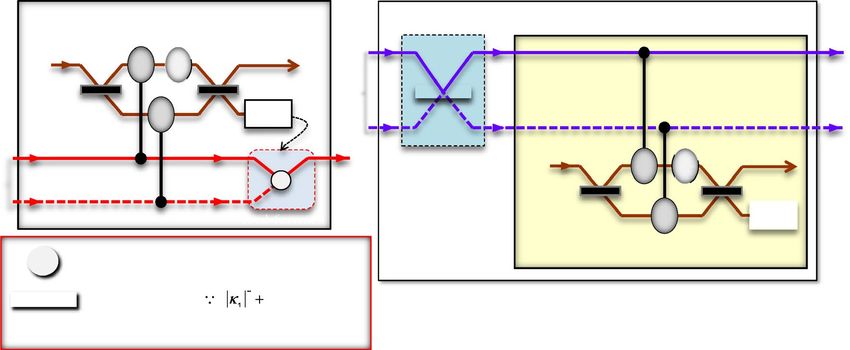
www.nature.com/scientificreports/
Figure 1. Schematic diagram of the interaction of XKNL: In the Figure, this interaction, conditional phase shift
θ into the phase space of the coherent state P, |α� P, is induced by the polarization |V � P (path 2) of the photon
A in the Kerr medium. Here, the photon and coherent state P play the roles of the control qubit, signal system
a
|V � 2P, and target qubit, ancillary system αeiθ P, respectively.
easurements10,12,14,16,18,66 in nonlinear optical gates via XKNLs with a strong amplitude of coherent states (qubus
m
beams), the decoherence effect should be r educed57–59.
In this study, we designed a photonic procedure based on nonlinear optical gates using XKNLs, qubus beams,
and PNR measurements to encode quantum information onto four-photon decoherence-free states (single logi-
cal qubit information) to achieve robustness against collective decoherence32–34. Subsequently, using XKNLs,
we quantified the efficiencies and performances of nonlinear optical gates under the decoherence effect (photon
loss and d ephasing57–59,63,65). In addition, we derived an experimental condition to reduce the decoherence effect
in nonlinear optical gates.
We demonstrate that the proposed procedure for generating single logical qubit information (quantum infor-
mation on four-photon decoherence-free states) with immunity against collective decoherence can be realized
experimentally and that it is robust against the decoherence effect (photon loss and dephasing).
Optical procedure via XKNLs for single logical qubit information
Four‑qubit decoherence‑free state. To prevent quantum information in qubits from being affected by
collective decoherence32–34, logical qubits using decoherence-free s ubspaces37–48 have been utilized. Herein, logi-
cal qubits {|0L �, |1L �} based on the four-qubit decoherence-free state are expressed as
1 1 1
|0L � 1234 ≡ (|0101� + |1010� − |0110� − |1001� )1234 = √ (|01� − |10� )12 ⊗ √ (|01� − |10� )34 ,
2 2 2
1
|1L � 1234 ≡ √ (2|0011� + 2|1100� − |0101� − |1010� − |0110� − |1001� )1234 (1)
12
1 1 1
= √ (|0011� + |1100� )1234 − √ (|01� + |10� )12 ⊗ √ (|01� + |10� )34 .
3 2 2
Using the logical qubits in Eq. (1) (four-qubit decoherence-free states), we can encode arbitrary quantum
information to acquire immunity against collective decoherence, as |φL � = α|0L � + β|1L � with |α|2 + |β|2 = 1
(single logical qubit information).
Interaction of XKNL. For the interaction, UK , in Kerr medium, XKNL, which can be employed to realize
the diverse quantum information processing schemes, the interaction between a photon A, signal system, and
coherent state P, ancillary system, to induce a phase shift θ by the Kerr medium is described in Fig. 1. For exam-
ple, we assume an input state, |R� A ⊗|α� P, to represent the interaction of the XKNL where
2 αn
|α� = e−|α| /2 ∞ n=0 n! |n�. After the input state passes through a polarizing beam splitter (PBS), the state is
√
transformed by the interaction (dotted-red box in Fig. 1) of XKNL, as follows:
PBS 1
UK 1
1
a
|R� 1A ⊗|α� aP → √ |H� 1A + |V � 2A ⊗|α� aP → √ |H� 1A ⊗|α� aP + UK |V � 2A ⊗|α� aP = √ |H� 1A ⊗|α� aP + |V � 2A ⊗
αeiθ � P ,
2 2 2
(2)
where the operations of the interaction, conditional phase shift, by XKNL and the PBS are described in Fig. 1.
As described in Fig. 1 and Eq. (2), the phase of ancillary system, |α� aP, is changed, according to the state, |H� 1A or
|V � 2A, of signal system via the interaction of XKNL. From this interaction, or procedure, we can realize quantum
non-demolition detections10,12,14,16,18,56–66, which can obtain the information of signal system by the indirect
detection in ancillary system, to utilize the various procedure for quantum information processing. For the
interaction of XKNLs, the magnitude of XKNL can obtain to ∼ 10−2, due to the electromagnetically induced
transparency67,68. Recently, to the measurement-induced quantum operation on weak quantum states of light69
can generate a strong XKNL at the single photon level for the applicable
quantum
information processing. Also,
for the Hamiltonian, HK = ℏχN1 N2, of XKNL with χ = g12 g22 / ��2c , the s cheme70 have been designed in
Scientific Reports | (2021) 11:10423 | https://doi.org/10.1038/s41598-021-89809-w 2
Vol:.(1234567890)
www.nature.com/scientificreports/
Figure 2. Procedure via XKNLs for single logical qubit information: First part is to generate the superposition
of four-photon decoherence-free states. In this part, two-photon interaction of XKNLs is used in the first gate,
and the fourth gate (via XKNLs) can merge photon paths. Meanwhile, the second and third gates are operated
by three-photon interactions of XKNLs. In the second part, the encoding process can encode (arbitrary)
quantum information onto four-photon decoherence-free states, which are output states of the first part.
circuit QED where gi is coupling strength, c is the transition strength between levels driven by a classical pump
field with , detuning. This can show the Kerr medium can be substituted by circuit QED as the proposition71
in which the non-maximal entangled states of photons can be concentrated.
Procedure via XKNLs for single logical qubit information. Our procedure pertaining to single logi-
cal qubit information comprises two parts: in the first part, four-photon decoherence-free states (the super-
position of logical qubits) are generated; in the second part, quantum information is encoded, as described in
Fig. 2. In this procedure, all gates, first, second, third, fourth, and final gates, employ the interactions of XKNLs,
qubus beams, and PNR measurements. For the single logical qubit information, we prepared the initial state as
ABCD = |L� A ⊗ |L� B ⊗ |R� C ⊗ |R� D, where |R�-right; |L�-left and linear |H�-horizontal; |V �-vertical repre-
|ψin � 1111 1 1 1 1
sent the circular and linear polarizations of photon, respectively (Fig. 1). After the initial state, |ψin � 1111
ABCD passes
two 50/50 beam splitters (BSs), and the four-photon state |ψ0 � ABCD can be expressed as
√
√
|ψ0 � ABCD = |L� 1A ⊗ |L� 1B ⊗ |R� 1C + |R� 2C / 2 ⊗ |R� 1D + |R� 2D / 2, (3)
where the operation of the BS is illustrated in Fig. 2.
In the first gate, two-photon interactions between photons C and D, shown in Fig. 3, four conditional phase
shifts θ by XKNLs, two linear phase shifts −θ, qubus beams (two BSs and PNR measurement), and feed-forward
(phase shifter and path switch) were exploited for a controlled operation between photons C and D. After the
′
state |ψ0 � ABCD passes through the first gate, the pre-measurement (before PNR measurement) state ψ0 �
ABCD
can be expressed as
′
1 1 1 1 1 1 1 2 2 a b
ψ0 � = |L� A |L� B ⊗ √ √ |R� C |R� D + √ |R� C |R� D ⊗ |α� P |0� P
ABCD 2 2 2
∞
(4)
1 − (αsinθ )2 (iαsinθ )n 1 1 2 (−1)n 2 1 a b
+ √ e 2 √ √ |R� C |R� D + √ |R� C |R� D ⊗ |αcosθ� P |n� P ,
2 n=0
n! 2 2
where |α� P is the coherent state, probe beam: ancillary system. The operation of the BS in the qubus beam (coher-
2 n
ent state) is shown in Fig. 3. |±iαsinθ� P = e−(αsinθ ) /2 ∞ n=0
√ ) |n� P for α ∈ R . Subsequently, by PNR
(±iαsinθ
n!
measurement on path b of the qubus beams, if the outcome is 0 ( |0� bP : no detection), then the output state,
√
|ψ1 � ABCD of the first gate can be obtained as |ψ1 � ABCD = |L� 1A |L� 1B |R� 1C |R� 1D + |R� 2C |R� 2D / 2 . Meanwhile,
√
if the outcome is n (|n� bP : n = 0 ), then the output state |L� 1A |L� 1B |R� 1C |R� 2D + (−1)n |R� 2C |R� 1D / 2 can be
transformed to state |ψ1 � ABCD by feed-forward (phase shifter and path switch), as described in Fig. 3.
Scientific Reports | (2021) 11:10423 | https://doi.org/10.1038/s41598-021-89809-w 3
Vol.:(0123456789)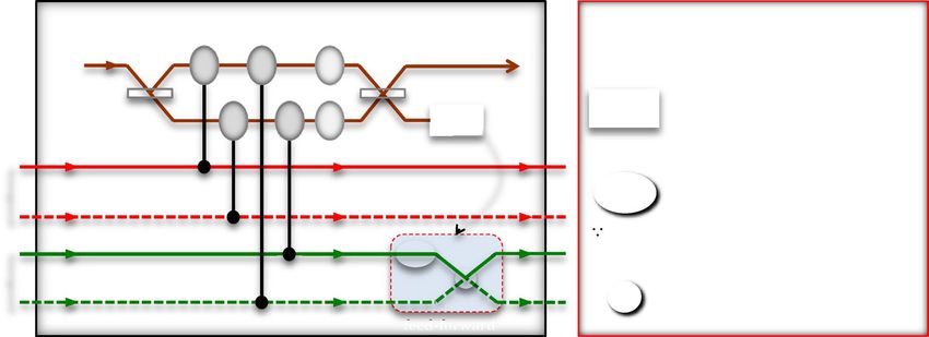
www.nature.com/scientificreports/
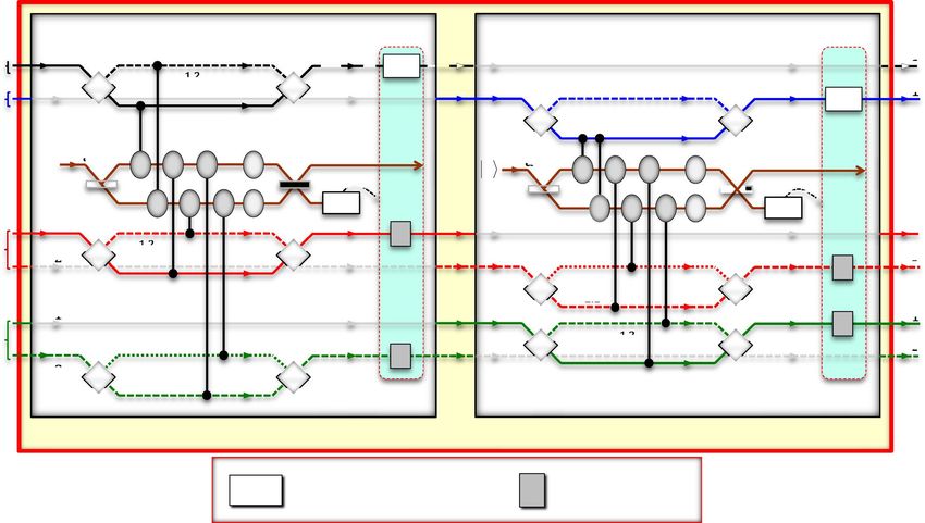
Figure 3. First gate (two-photon interactions between photons C and D) via XKNLs: For path arrangement of
photons C and D, the first gate comprises XKNLs, qubus beams, PNR measurement, feed-forward, and linear
optical devices. After PNR measurement, feed-forward (phase shifter and path switch) on photon D is either
operated or not operated, depending on the result (photon number n) of PNR measurement.
Figure 4. Second and third gates (three-photon interactions) via XKNLs: For controlled operations between
three photons, two (second and third) gates consist of XKNLs, qubus beams, PNR measurement, feed-forward,
and linear optical devices were used. Feed-forwards (phase shifters and spin flippers) of two gates are either
operated or not operated on photons (A, C, and D: second gate) and (B, C, and D: third gate) depending on
results of PNR measurements.
In the second and third gates, which interact with three-photon, shown in Fig. 4, conditional phase shifts θ
by XKNLs, linear phase shifts −θ, qubus beams (BSs and PNR measurements), feed-forwards (phase shifters and
spin flippers), and linear optical devices, including polarizing beam splitters (PBSs), were utilized for controlled
operations between three photons, i.e., (A, C, and D: second gate) and (B, C, and D: third gate). After the state
|ψ1 � ABCD (the output state of the first gate) passes through the second gate, the pre-measurement (before PNR
′
measurement) state ψ1 � can be expressed as
ABCD
Scientific Reports | (2021) 11:10423 | https://doi.org/10.1038/s41598-021-89809-w 4
Vol:.(1234567890)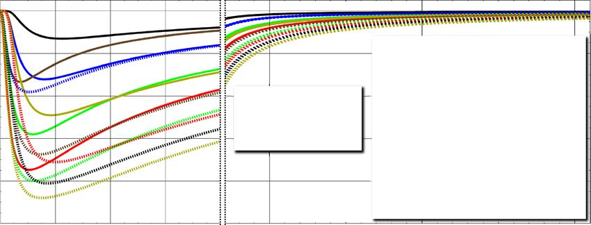
www.nature.com/scientificreports/
′
1 1
1
ψ1 � = √ |H� 1A |L� 1B |V � 1C |R� 1D + |R� 2C |V � 2D − |V � 1A |L� 1B |H� 1C |R� 1D + |R� 2C |H� 2D ⊗ |α� aP |0� bP
ABCD 2 2 2
∞ n
1 (αsinθ)2 (iαsinθ ) 1
+ √ e− 2 √ |H� 1A |L� 1B |H� 1C |R� 1D + |R� 2C |H� 2D
2 n! 2
n=0
(−1)n
− |V � 1A |L� 1B |V � 1C |R� 1D + |R� 2C |V � 2D ⊗ |αcosθ� aP |n� bP .
2
(5)
Depending on the PNR measurement result on path b of the qubus beams, if the outcome is 0 (|0� bP: no detec-
t i on ) , t h e n t h e o
ut p ut s t at e , |ψ2 � ABCD
of t h e
s e c on d g at e c a n
be obtained as
|ψ2 � ABCD = |H� 1A |L� 1B |V � 1C |R� 1D + |R� 2C |V � 2D − |V � 1A |L� 1B |H� 1C |R� 1D + |R� 2C |H� 2D /2 . Otherwise, if n
(|n� bP: n = 0), then the output state can be changed to |ψ2 � ABCD by feed-forwards (phase shifter and spin flippers).
Subsequently,
the state |ψ2 � ABCD enters the third gate for another controlled operation. After the third gate, the
′
state ψ2 � (before PNR measurement) can be written as
ABCD
′
1 1
ψ2 � = √ √ |H� 1A |H� 1B |V � 1C |V � 1D + |V � 2C |V � 2D − |V � 1A |H� 1B |H� 1C |V � 1D + |V � 2C |H� 2D
ABCD 2 2 2
1
+ √ |V � 1A |V � 1B |H� 1C |H� 1D + |H� 2C |H� 2D − |H� 1A |V � 1B |H� 2C |V � 2D + |V � 1C |H� 1D ⊗ |α� aP |0� bP
2 2
2 ∞
1 − (αsinθ) (iαsinθ)n 1
+√ e 2 √ √ |H� 1A |H� 1B |V � 1C |H� 1D + |H� 2C |V � 2D − |V � 1A |H� 1B |H� 1C |H� 1D + |H� 2C |H� 2D
2 n=0
n! 2 2
(−1)n
+ √ |V � A |V � B |H� C |V � 1D + |V � 2C |H� 2D − |H� 1A |V � 1B |V � 1C |V � 1D + |V � 2C |V � 2D
1 1 1 ⊗ |αcosθ� aP |n� bP .
2 2
(6)
After the operations applying feed-forwards or not in Fig. 4, owing to the outcome of the PNR measurement,
the output state |ψ3 � ABCD of the third gate can be expressed as
1
√
√
|ψ3 � ABCD = |H� 1A |H� 1B ⊗ |V � 1C |V � 1D + |V � 2C |V � 2D / 2 − |V � 1A |H� 1B ⊗ |H� 1C |V � 1D + |V � 2C |H� 2D / 2
2
√
√
+ |V � 1A |V � 1B ⊗ |H� 1C |H� 1D + |H� 2C |H� 2D / 2 − |H� 1A |V � 1B ⊗ |H� 2C |V � 2D + |V � 1C |H� 1D / 2 .
(7)
Subsequently, as described in Fig. 2, two BSs were applied to photons
C and D of the output state |ψ3 � ABCD
′
in Eq. 7. Next, the output state |ψ3 � ABCD was transformed to state ψ3 � of the superposed (four-photon)
ABCD
decoherence-free states, as follows:
′ 1
ψ3 � = √ |H� 1A |V � 1B |H� 1C |V � 2D + |V � 1A |H� 1B |V � 1C |H� 2D − |H� 1A |V � 1B |V � 1C |H� 2D − |V � 1A |H� 1B |H� 1C |V � 2D
ABCD 4 2
+ |H� 1A |V � 1B |H� 2C |V � 1D + |V � 1A |H� 1B |V � 2C |H� 1D − |H� 1A |V � 1B |V � 2C |H� 1D − |V � 1A |H� 1B |H� 2C |V � 1D
+ 2|H� 1A |H� 1B |V � 1C |V � 1D + 2|V � 1A |V � 1B |H� 1C |H� 1D − |V � 1A |H� 1B |H� 1C |V � 1D − |H� 1A |V � 1B |V � 1C |H� 1D
−|H� 1A |V � 1B |H� 1C |V � 1D − |V � 1A |H� 1B |V � 1C |H� 1D + 2|H� 1A |H� 1B |V � 2C |V � 2D + 2|V � 1A |V � 1B |H� 2C |H� 2D
− |V � 1A |H� 1B |H� 2C |V � 2D − |H� 1A |V � 1B |V � 2C |H� 2D − |H� 1A |V � 1B |H� 2C |V � 2D − |V � 1A |H� 1B |V � 2C |H� 2D
√ √
1 1 3 1 1 3
≡ √ |0L � 1112
ABCD + |1L � 1111
ABCD + √ |0L � 1121
ABCD + |1L � 1122
ABCD ,
2 2 2 2 2 2
(8)
where we define the polarizations (|H� and |V �) of photons corresponding to states (|0� and |1�) of the qubit
′
as {|H� , |V � } ≡ {|0� , |1� }. Hence, state |ψ3 �ABCD is the photonic superposition of logical qubits (four-qubit
decoherence-free states in Eq. 1), according to the paths of photons C and D.
In the fourth gate (photon C) shown in Fig. 5, two conditional phase shifts θ by XKNLs, one linear phase
shift −θ, qubus beams (two BSs and PNR measurement), and feed-forward (path switch) were utilized to merge
′
the path of photon C (path 1 and path 2 → path 1). After state |ψ3 �ABCD passes through the fourth gate, the pre-
′′
measurement (before PNR) state |ψ3 �ABCD can be expressed as
√
′′
ψ �ABCD = √1 1 |0L � 1112 + 3 |1L � 1111 a b
3 ABCD ABCD ⊗ |α� P |0� P
2 2 2
∞
√
(9)
1 − (αsinθ )2
(−iαsinθ)n 1 1121 3 1122 a b
+√ e 2 √ |0L � ABCD + |1L � ABCD ⊗ |αcosθ� P |n� P .
2 n! 2 2
n=0
Subsequently, by PNR measurement
on path b of the qubus
beams, if the outcome is 0 (|0� P: no detection),
b
√
ABCD + 3|1L � ABCD /2. Meanwhile, if the outcome is n (|n� P : n = 0),
then output state is |ψ4 � ABCD = |0L � 1112 1111 b
Scientific Reports | (2021) 11:10423 | https://doi.org/10.1038/s41598-021-89809-w 5
Vol.:(0123456789)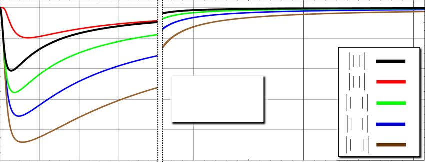
www.nature.com/scientificreports/
Figure 5. Fourth gate via XKNLs; encoding process with arbitrary-BS and final gate (XKNLs): The fourth gate
merged the path of photon C using XKNLs, qubus beams, PNR measurement, and feed-forward (path switch).
During encoding, the arbitrary-BS (linear optical device) and final gate (via XKNLs) encode arbitrary quantum
information onto four-photon decoherence-free states (single logical qubit information).
√
then the output state |0L � 1121
ABCD + 3|1L � ABCD /2 can be transformed to state |ψ4 � ABCD by feed-forward (path
1122
switch), as shown in Fig. 5.
The encoding process shown in Fig. 5 comprises two parts (linear: arbitrary-BS, and nonlinear: final gate via
XKNLs). To encode arbitrary quantum information for our purposes, communication, computation, teleporta-
tion, etc., onto the output state |ψ4 � ABCD of the fourth gate, we can control the transmission rate ( κ1) and reflec-
tion rate ( κ2) of an arbitrary-BS, in which the operations
are expressed as
described in Fig. 5. Therefore, after
√
applying the arbitrary-BS to state |ψ4 � ABCD = |0L � ABCD + 3|1L � 1111
1112
ABCD /2, the encoded (superposition of)
state |ψ5 � ABCD is expressed as
1 1
√
1
√
|ψ5 � ABCD = √
κ1 |0L � 1111
ABCD + 3κ2 |1L � 1111
ABCD −
κ2 |0L � 1112
ABCD − 3κ1 |1L � 1112
ABCD
2 3|κ2 |2 + |κ1 |2 3|κ1 |2 + |κ2 |2
1
≡ √ α1 |0L � 1111 1111 1112 1112
ABCD + β1 |1L � ABCD − α2 |0L � ABCD − β2 |1L � ABCD ,
2
(10)
where |αi |2 + |βi |2 = 1. αi and βi denote the arbitrary information encoded by the arbitrary-BS. Subsequently,
′
through the final gate, the pre-measurement (before PNR measurement) state ψ5 � is expressed as
ABCD
′ 1
b
ψ5 � = √ α1 |0L � 1111 1111 a
ABCD + β1 |1L � ABCD ⊗ |α� P |0� P
ABCD 2
∞
(αsinθ)2
(−iαsinθ)
n
(11)
1
− √ e− 2 √ α2 |0L � 1112 1112 a b
ABCD − β2 |1L � ABCD ⊗ |αcosθ� P |n� P .
2 n=0
n!
After PNR measurement on path b, we can obtain the final state (single logical qubit information), which
is the encoded arbitrary information, for the outcomes (n = 0 or n = 0) of the PNR measurement, as follows:
(n = 0) → ψf _0 � ABCD = α1 |0L � 1111 1111
ABCD + β1 |1L � ABCD ,
(12)
(n �= 0) → ψf _n � = α2 |0L � 1112 − β2 |1L � 1112 ,
ABCD ABCD ABCD
where the final state ψf _n ABCD (n = 0) can be converted to state ψf _0 ABCD (n = 0) by applying unitary opera-
tions since the transmission rate, κ1, and reflection rate, κ2, of an arbitrary-BS are known. Consequently, for the
single logical qubit information, the proposed procedure shown in Fig. 2 can encode the arbitrary quantum
information ( αi and βi ) onto four-photon decoherence-free states which are superposed state of |0L � and |1L �,
as shown in Eq. (12).
Herein, we propose a procedure comprising nonlinear optical gates, first, second, third, fourth, and final gates
via XKNLs, and linear optical devices, including the arbitrary-BS, to encode single logical qubit information
onto logical qubits (four-photon decoherence-free states) to protect quantum information against collective
decoherence32–34. However, the nonlinear optical gates, which are components critical to this procedure (Fig. 2),
cannot avoid the influences of photon loss and dephasing induced by the decoherence effect57–59,63,65,72,73. There-
fore, we should derive the experimental condition to reduce the decoherence effect57–59,63,65 based on the master
equation74 to quantify the efficiency and performance of the nonlinear optical gates.
Scientific Reports | (2021) 11:10423 | https://doi.org/10.1038/s41598-021-89809-w 6
Vol:.(1234567890)
www.nature.com/scientificreports/
Quantification of efficiency and performance of nonlinear optical gates via XKNLs
under decoherence effect
In the proposed procedure, the nonlinear optical gates, first, second, third, fourth, and final gates, using XKNLs
are the most important components for generating decoherence-free states (logical qubits) and encoding arbitrary
quantum information. Hence, these gates must be highly efficient and reliable when the proposed procedure
is implemented in optical fi bers72,73. Regarding the interaction of XKNLs of these gates, we should derive an
experimental condition to decrease the decoherence effect57–59,63,65 using the master equation74, which can indicate
the open quantum system, as follows:
∂ρ(t) −i 1
+
= [HK , ρ] + γ aρa+ − a aρ + ρa+ a , (13)
∂t ℏ 2
where HK = ℏχN1 N2. The Lindblad operators are Jρ = γ aρa+ and Lρ = − γ2 a+ aρ + ρa+ a , where γ is the
energy decay rate. The solution to this equation is ρ(t) = exp
J +
L t ρ(0) for time t(= θ/χ). Using this solu-
tion, we can exploit the process model, which can be used to formulate the influences of photon loss and dephas-
ing of coherent parameters caused by the interaction (conditional phase shift) of XKNLs in nonlinear optical
gates under the decoherence effect, as follows:
N
N
2 −γ �t in�θ −γ �t(n−1)
D̂�t X̂�t |1� � 0|⊗|α� � α| = exp −α 1 − e 1−e e |1� � 0|⊗�t αeiθ �� �t α| ,
n=1
(14)
N
where D̂t X̂t = D̂ t X̂ t for θ = χ t = χN�t = N�θ owing to an arbitrarily small time �t(= t/N) for
obtaining a good approximation57–59,63,65. Here, the decoherence D̂t (photon loss and dephasing) and the rate,
�t = e−γ t/2 of the remaining photons in the probe beam can be calculated from the solution of the master equa-
tion shown in Eq. (13). Furthermore, the operation of the operator X̂t (of the interaction of XKNLs) is expressed
N
as X̂�t |1� � 0| ⊗ |α� � α| = |1� � 0| ⊗
αeiN�θ �� α| = |1� � 0| ⊗
αeiθ �� α| for |1� (one photon) and |0� (zero
photon). Using this process model (decoherence: D̂t and interaction of XKNL: X̂t ) of Eqs. (13) and (14), we can
quantify the influences of photon loss (�t = e−γ t/2) and dephasing of the value of the coherent parameter, i.e.,
the coefficient of the right-hand side of Eq. (14), induced by the decoherence effect. For the large phase shift
(≈ π ) at room temperature, researchers in Ref.75 demonstrated that the implementation of large phase shifts on
a single-photon level probe pulse (1.5µs) is mediated by Rb87 vapor in a double- atomic configuration to apply
to quantum non-demolition detections 10,12,14,16,18,56–64. Also, for the practical realization of nonlinear optical
gates, we should consider the experimental parameters and the features in the optical fibers72,73. In commercial
fibers, which are pure silica-core fibers with a signal loss of 0.15 dB/km (χ/γ = 0.0303)73, a length of approxi-
mately 3000 km is required to acquire the magnitude of the conditional phase shift, θ = π from XKNLs. Hence,
using the process model (Eqs. 13 and 14) with the experimental parameters and features of the optical fiber
(length of 3000 km for θ = π and signal loss of 0.15 dB/km), we can analyze and quantify the efficiencies and
performances of the nonlinear optical gates in the proposed procedure for encoding single logical qubit informa-
tion (Fig. 2).
For the quantification of efficiency in ideal cases without the decoherence effect, we can obtain the error prob-
abilities of nonlinear optical gates from the probabilities
2 of2 measuring
state
|0�2P (zero
b
photon) in state |±iαsinθ� bP
(Eqs. 4, 5, 6, 9, and 11), as follows: Perr = exp −α sin θ /2 ≈ exp −α θ /2 for α sin2 θ ≈ α 2 θ 2 with a
2 2
strong amplitude of coherent state and small phase shift magnitude by the XKNL ( α ≫ 1 and θ ≪ 1). If we do
not consider the decoherence effect (ideal case), then the error
probabilities
of all nonlinear optical gates (first,
second, third, fourth, and final) will be identical, as Perr ≈ exp −α 2 θ 2 /2. In addition, when the parameter is
fixed as αθ = 2.5, we can acquire highly efficient nonlinear optical gates (first, second, third, fourth, and final)
because Perr < 10−3.
However, in the practical cases where the decoherence effect is considered, we should recalculate the error
probabilities (P1st err , Perr , Perr , Perr , and Perr ) including the photon loss (the rate �t = e
2nd 3rd 4th fin −γ t/2 of remaining pho-
tons) due to the decoherence effect, as follows:
1st
4 2 2
−2γ t 2
2.5
−2 α×0.0303 2
Perr = exp −�t α θ /2 = exp −e × 2.5 /2 = exp −e × 2.5 /2,
−3γ t
2.5
−3 α×0.0303
P2nd
err = P 3rd
err = exp −� 6 2 2
t α θ /2 = exp −e × 2.5 2
/2 = exp −e × 2.5 2
/2,
− 2.5
P4th fin
err = Perr = exp −�t α θ
2 2 2
/2 = exp −e−γ t × 2.52 /2 = exp −e α×0.0303 × 2.52 /2,
(15)
where γ t = 2.5/(α × 0.0303) for �t = e−γ t/2 with a fixed αθ = αχt = 2.5, and a signal loss of 0.15 dB/km
(χ/γ = 0.0303) in optical fibers73. From these calculations, we can obtain the efficiency values of the nonlinear
optical gates under the decoherence effect. Figure 6 shows the tendencies of the error probabilities (P1st err , Perr ,
2nd
Perr , Perr , and Perr ) and rates ( t , t , and t ) of the remaining photons of the gates (first, second, third, fourth,
3rd 4th fin 4 6 2
and final) in terms of the differences in the amplitude of the coherent state ( α) with the following parameters:
Scientific Reports | (2021) 11:10423 | https://doi.org/10.1038/s41598-021-89809-w 7
Vol.:(0123456789)www.nature.com/scientificreports/
Figure 6. Error probabilities and rates of remaining photons in probe beam in practical case (under
decoherence effect): Graph shows error probabilities (P1st
err , Perr , Perr , Perr , and Perr ) and rates (�t = e
2nd 3rd 4th fin −γ t/2) of
remaining photons of nonlinear optical gates (first, second, third, fourth, and final) for differences in amplitude
(α) of coherent state with fixed αθ = 2.5 and signal loss of 0.15 dB/km (χ/γ = 0.0303). Values of error
probabilities and rates of remaining photons in each gate are listed in table.
signal loss of 0.15 dB/km (χ/γ = 0.0303), αθ = αχt = 2.5, and N = 103. In addition, the values of error prob-
abilities (P1st
err , Perr , Perr , Perr , and Perr ) and rates ( t , t , and t ) of the remaining photons of the gates were
2nd 3rd 4th fin 4 6 2
calculated for the amplitudes, α=10, 100, 1000, 10000, and 100000, of the coherent state, as listed on Table (in
Fig. 6). Compared with the dotted-blue box and dotted-red box in Table, we can conclude that high efficien-
cies, i.e., Perr < 10−3 (and low rate, t ≈ 1.0 of photon loss), can be achieved in the nonlinear optical gates by
employing a strong amplitude of coherent state ( α ≫ 10) under the decoherence effect.
Moreover, we should analyze the performances, the influence of dephasing, of the nonlinear optical gates, in
addition to the efficiencies which are quantified by error probabilities by photon loss in Fig. 6. To quantify the
influences of dephasing of coherent parameters induced by the decoherence effect, we require a process model
(Eqs. 13 and 14) that can describe the dynamics of the interactions of XKNLs ( X̂t ) and the decoherence effect
( D̂t ) to analyze the output states from the nonlinear optical gates.
In the first, fourth, and final gates, using the process model’s formula (Eqs. 13 and 14), the output states
′ ′′ ′ ′
ψ0 � in Eq. (4), ψ3 � in Eq. (9), and ψ5 � in Eq. (11) can be expressed as density matrices ρ0 of
ABCD ABCD ABCD
′′ ′
the first gate, ρ3 of the fourth gate, and ρ5 of the final gate, respectively, to determine the dephasing of coherent
parameters, as follows:
1 |CK|2 |L|2 |CO|2 � �
′ 1 |CK|2 1 |CO|2 |L|2 , ρ ′′ = ρ ′ = 1 1 |C|2
ρ0 = 2 2 2 2 , (16)
4 |L| |CO| 1 |CM| 3 5
2 |C| 1
2
|CO| |L| |CM| 2 2
1
a a
where the bases of ρ0′ are the states in |L� 1A |L� 1B |R� 1C |R� 1D �2t α� P |0� bP , |L� 1A |L� 1B |R� 2C |R� 2D �2t α� P |0� bP ,
a b a b ′′
|L� 1A |L� 1B |R� 1C |R� 2D �2t αcosθ� P i�2t αsinθ� P, and |L� 1A |L� 1B |R� 1C |R� 2D �2t αcosθ� P −i�2t αsinθ� P; the bases of ρ3
√
√
are the states in 12 |0L � 1112 ABCD + 2 |1L � ABCD |�t α� P |0� P and 2 |0L � ABCD + 2 |1L � ABCD |�t αcosθ� P
3 1111 a b 1 1121 3 1122 a
′
|−i�t αsinθ� bP ; the bases of ρ5 are the states in α1 |0L � 1111 ABCD + β1 |1L � ABCD |�t α� P |0� P and
1111 a b
ABCD − β2 |1L � ABCD |�t αcosθ� P |−i�t αsinθ� P from left to right and top to bottom. Based on the process
b
α2 |0L � 1112 1112 a
′ ′′ ′
model expressed in Eq. (14), the coherent parameters in the density matrices (ρ0, ρ3 , and ρ5) are expressed as
√
2
N
C = exp − α/ 2 1 − e−γ �t 1 − ein�θ e−γ �t(n−1) ,
n=1
Scientific Reports | (2021) 11:10423 | https://doi.org/10.1038/s41598-021-89809-w 8
Vol:.(1234567890)www.nature.com/scientificreports/
Figure 7. Trends and values of coherent parameters in output states of first, fourth, and final gates by
dephasing (decoherence effect): Graph represents coherent parameters in output states of the nonlinear optical
gates (first, fourth, and final) for differences in amplitude (α) of coherent state with signal loss of 0.15 dB/km
(χ/γ = 0.0303), αθ = 2.5 (Perr < 10−3), and N = 103. Values of coherent parameters in output states are listed
in table.
√
2
N
L = exp − α/ 2 e−γ t 1 − e−γ �t 1 − ein�θ e−γ �t(n−1) ,
n=1
−γ �t(n−1)
√
2
N
−in�θ
K = exp − α/ 2 e−γ t 1 − e−γ �t 1 − eiθ · e e ,
n=1
−γ �t(n−1)
√
2
−γ t
−γ �t
N
iθ in�θ
M = exp − α/ 2 e 1−e 1−e ·e e ,
n=1
√
2
N −γ �t(n−1)
O = exp − α/ 2 e−γ t 1 − e−γ �t 1 − eiθ e , (17)
n=1
where for θ = χt = χ N�t = N�θ and α ∈ R with an arbitrarily small time �t = t/N (for a good
′ ′′ ′
approximation57–59,63,65). In the density matrices ( ρ0 , ρ3 , and ρ5 ), the off-diagonal terms refer to the coher-
ent parameters (C , L , K , M, and O) that can be used to evaluate the degrees of a mixed state and quantify the
influences of dephasing. For example, if the values of the coherent parameters (off-diagonal terms) decrease by
′ ′′ ′
dephasing (decoherence effect), then the output states (ρ0 of the first gate, ρ3 of the fourth gate, and ρ5 of the
final gate) evolve into mixed states, the ensemble of classical states. Therefore, to obtain reliable performances
from the nonlinear optical gates, first, fourth, and final gates, the values of the coherent parameters should be
retrained to approach 1 for the pure quantum state against
dephasing
by the decoherence
effect. Figure 7 shows
′
the tendencies of the coherent parameters ( |C|2 , |L|2 , |KC|2 , |OC|2 , and |MC|2 ) in the density matrices (ρ0,
′′ ′
ρ3 , and ρ5) of the first, fourth, and final gates for the amplitude of the coherent state, probe beam: α, with the fol-
lowing parameters: signal loss of 0.15 dB/km (χ/γ = 0.0303), αθ = αχt = 2.5 (Perr < 10−3), and N = 103 under
the decoherence effect. In addition, based on the table shown in Fig. 7, we calculated the values of the coherent
parameters based on the differences in the amplitudes ( α=10, 100, 1000, 10000, and 100000) of the probe beams.
As shown in Fig. 7, if the amplitude of the coherent state (probe beam) increases ( α ≫ 100), then all values of
the coherent parameters are approximately 1. Hence, by employing the strong (large amplitude) coherent state,
′ ′′ ′
we can maintain the output state (ρ0, ρ3 , and ρ5) of the first, fourth, and final gates to pure quantum states (pre-
vention of off-diagonal terms in the density matrices, Eq. 16) against the influence of dephasing induced by the
decoherence effect. Herein, as shown by the dotted blue box, the values of coherent parameters are high (> 0.9)
when the amplitude of the coherent state is small (α = 10), compared with the values within the dotted-red box
in Fig. 7. However, in the small amplitude range (α < 10) of the coherent state, we could not acquire a high rate
of highly efficient remaining photons in the first, fourth, and final gates, as shown in Fig. 6 (dotted-blue box).
Scientific Reports | (2021) 11:10423 | https://doi.org/10.1038/s41598-021-89809-w 9
Vol.:(0123456789)www.nature.com/scientificreports/
Hence, for high efficiencies (low error probabilities) and reliable performances (preserved pure quantum states
in the output) in the first, fourth, and final gates, we should utilize the strong coherent state (probe beam) to
reduce the influences of photon loss and dephasing.
′
In the second and third gates, using the process model’s formula (Eqs. 13 and 14), the output states ( ψ1 �
ABCD
′ ′ ′
in Eq. 5 and ψ2 � in Eq. 6) can be expressed as density matrices ρ1 of the second gate and ρ2 of the third
ABCD
gate, as follows:
1 |LN|2 C∗ K ∗ C∗ LO∗ |N|2 |P|2 C∗ K∗ |P|2 |LR|2 C∗ LO∗ |R|2
|LN|2 1 ∗
C LO |N|∗ 2 ∗
C K ∗ |LR| 2 ∗ ∗
C LO |R| 2 |P| 2 ∗ ∗
C K |P| 2
CK CL∗ O|N|2 1 |CON|2 CK|P|2 |P|2 CL∗ O|R|2 |COR|2
′ ′ 1 CL∗ O|N|2 CK |CON|2 1 CL∗ O|R|2 |COR|2 CK|P|2 |P|2
ρ1 = ρ2 = 2 2 ∗ K ∗ |P|2 C∗ LO∗ |R|2 2
∗ LO∗ |S|2 ,
8 |P| |LR| C 1 CK |LS| C
CK|P|2 CL∗ O|R|2 |P| 2 |COR| 2
C K∗ ∗ 1 ∗
CL O|S| 2 |COS| 2
|LR|2 |P|2 C∗ LO∗ |R|2 C∗ K∗ |P|2 |LS|2 C∗ LO∗ |S|2 1 C∗ K ∗
∗ 2 2 |COR| 2 |P| 2 ∗ 2 |COS| 2
CL O|R| CK|P| CL O|S| CK 1
(18)
′ a a
where the bases of ρ1 are the states in |H� 1A |L� 1B |V � 1C |R� 1D �3t α� P |0� bP , |H� 1A |L� 1B |R� 2C |V � 2D �3t α� P |0� bP ,
a a a b
|V � 1A |L� 1B |H� 1C |R� 1D �3t α� P |0� bP ,|V � 1A |L� 1B |R� 1C |H� 1D �3t α� P |0� bP,|H� 1A |L� 1B |H� 1C |R� 1D �3t αcosθ� P i�3t αsinθ� P,
a b a b
|H� 1A |L� 1B |R� 2C |H� 2D �3t αcosθ� P i�3t αsinθ� P , |V � 1A |L� 1B |V � 1C |R� 1D �3t αcosθ� P −i�3t αsinθ� P , and |V � 1A |L� 1B
a b ′
|R� 2C |V � 2D �3t αcosθ� P −i�3t αsinθ� P; the bases of ρ2 are the states in √1 |H� 1A |H� 1B |V � 1C |V � 1D + |V � 2C |V � 2D
3 a b 2
� α� |0� , √1 |V � 1 |H� 1 |H� 1 |V � 1 + |V � 2 |H� 2
�3 α� a |0� b, √1 |V � 1 |V � 1 |H� 1 |H� 1 + |H� 2 |H� 2
�3 α� a |0� b,
t P P 2 A B C D C D t P P 2 A B C D C D t P P
a
a
√1 |H� 1 |V � 1 |H� 2 |V � 2 + |V � 1 |H� 1
�3 α� |0� b, √1 |H� 1 |H� 1 |V � 1 |H� 1 + |H� 2 |V � 2
�3 αcosθ�
i�3 αsinθ� ,
b
2 A B C D C D t P P 2 A B C D C D t P t P
a
b
√1 |V � 1 |H� 1 |H� 1 |H� 1 + |H� 2 |H� 2
�3 αcosθ�
i�3 αsinθ� , √1 |V � 1 |V � 1 |H� 1 |V � 1 + |V � 2 |H� 2
2 A B C D C D t P t P 2 A B C D C D
3
� αcosθ� a −i�3 αsinθ� b, and √1 |H� 1 |V � 1 |V � 1 |V � 1 + |V � 2 |V � 2
�3 αcosθ� a
−i�3 αsinθ� b from left to
t P t P 2 A B C D C D t P t P
right and top to bottom. The coherent parameters (C, L, K , M, and O) can be calculated using Eq. (17). The other
′ ′
coherent parameters (P, N, S, and R ) in density matrices (ρ1 and ρ2) can be calculated from the process model
(Eq. 14), as follows:
√
2
N
P = exp − α/ 2 e−2γ t 1 − e−γ �t 1 − ein�θ e−γ �t(n−1) ,
n=1
−γ �t(n−1)
√
2
N
−in�θ
N = exp − α/ 2 e−2γ t 1 − e−γ �t 1 − eiθ · e e ,
n=1
−γ �t(n−1)
√
2
−2γ t
−γ �t
N
iθ in�θ
S = exp − α/ 2 e 1−e 1−e ·e e ,
n=1
√
2
N −γ �t(n−1)
R = exp − α/ 2 e−2γ t 1 − e−γ �t 1 − eiθ e , (19)
n=1
where θ = χt = χ N�t = N�θ for an arbitrarily small time �t(= t/N) with α ∈ R. For the experimental con-
dition to preserve the values of coherent parameters to 1 (pure quantum states) under the decoherence effect,
′
we can determine the tendencies of the coherent parameters, off-diagonal terms, in the density matrices (ρ1 and
′
ρ2) of the second and third gates for the amplitude of the coherent state (probe beam: α) using the following
parameters: signal loss of 0.15 dB/km (χ/γ = 0.0303), αθ = αχt = 2.5 (Perr < 10−3), and N = 103, as shown
in Fig. 8. In addition, the values of the coherent parameters are listed on Table (in Fig. 8) based on the differences
in the amplitudes, α = 10, 100, 1000, 10000, and 100000, of the probe beams. When the amplitude of the coherent
state (probe beam) increased ( α ≫ 100), all values of the coherent parameters were approximately 1, similar to
′ ′′ ′
the coherent parameters in ρ0, ρ3 , and ρ5, as shown in Fig. 8. Therefore, we confirmed that the influences, which
′ ′
evolved to mixed states, of dephasing coherent parameters in ρ1 and ρ2 (Eq. 18) can be reduced using a strong
coherent state. Furthermore, by comparing with the dotted-blue box and dotted-red box in Fig. 8, the nonlinear
optical gates (second and third) can yield high efficiencies (low error probabilities) and reliable performances
(preserving pure quantum states) in the large amplitude range ( α > 100000) of the coherent state.
According to our analysis, using the process model (Eq. 14), which can be used to formulate the interaction
of XKNLs between a signal system (photon) and a probe beam (coherent state) via the master equation (Eq. 13),
we can conclude that the only experimental condition is to utilize the strong coherent state (probe beam) to
reduce the influences of photon loss and dephasing (decoherence effect). Hence, we can obtain high efficiencies
(low error probabilities, Fig. 6) and reliable performances (values of coherent parameters approaching 1: Figs. 7
and 8) in the nonlinear optical gates. Consequently, the proposed procedure for generating single logical qubit
information (quantum information on four-photon decoherence-free states) with immunity against collective
Scientific Reports | (2021) 11:10423 | https://doi.org/10.1038/s41598-021-89809-w 10
Vol:.(1234567890)www.nature.com/scientificreports/
Figure 8. Trends and values of coherent parameters in output states of second and third gates by dephasing
(decoherence effect): Graph represents coherent parameters in output states of nonlinear optical gates (second
and third) for differences in amplitude (α) of coherent state with signal loss of 0.15 dB/km (χ/γ = 0.0303),
αθ = 2.5 (Perr < 10−3), and N = 103. Values of coherent parameters in output states are listed in table.
decoherence can be experimentally implemented and is secure against photon loss and dephasing induced by
the decoherence effect.
Conclusion
We proposed a procedure (Fig. 2) that can generate four-photon decoherence-free states, logical qubits, and
encode quantum information onto the superposition of logical qubits (single logical qubit information) using
XKNLs and linear optical devices to secure quantum information against collective decoherence. In addition,
in the nonlinear optical gates, first, second, third, fourth, and final gates, we analyzed the influences of photon
loss and dephasing induced by the decoherence effect, and then demonstrated the experimental condition to
obtain high efficiencies and reliable performances for the feasible procedure (Fig. 2). The advantages of our
procedure are as follows:
(1) Our procedure can be used to encode single logical qubit information and secure quantum information
from collective decoherence using arbitrary information encoded onto the superposed state of four-photon
decoherence-free states. The previous works, which proposed three-qubit decoherence-free states37–41, can
provide the limited effect for the prevention against the affections of collective decoherence. Here, compared
with three-qubit s ystems37–41, our scheme can generate four-qubit systems (four-photon decoherence-free
states), which are more immune against collective decoherence, to maintain the coherence of quantum
information.
(2) In various quantum information processing schemes, including the procedure of generating decoherence-
free states, the noises, photon loss and dephasing, induced by the decoherence effect is inevitable. Thus,
the method to reduce the influences of decoherence effect should be proposed. Before the works42,43 using
cavity-QED system for four-qubit decoherence-free states, their schemes overlooked the affections of deco-
herence effect. Here, in our scheme, we discussed the quantifications of the influences of photon loss and
dephasing from the decoherence effect. Accordingly, we demonstrated the experimental condition by our
analysis using master equation to utilize a strong, large amplitude, coherent state for the high efficiencies,
low error probabilities, and reliable performances by preserving pure quantum state in nonlinear optical
gates under the decoherence effect. Thus, our scheme is experimentally more feasible, compared with the
previous works42,43.
Scientific Reports | (2021) 11:10423 | https://doi.org/10.1038/s41598-021-89809-w 11
Vol.:(0123456789)www.nature.com/scientificreports/
(3) In our procedure, the nonlinear optical gates utilized only the positive conditional phase shifts (θ) of the
XKNLs with qubus beams and PNR measurements because it is generally not possible to change the sign
of the conditional phase shift (−θ) by Kok76. Moreover, the usage of a strong coherent state (for high effi-
ciency and reliable performance) can yield an experimental advantage from using the weak conditional
phase shift magnitude of the XKNL (i.e., if we use α =105 to reduce the influence of the decoherence effect,
then the XKNL magnitude required is θ = 2.5 × 10⁻⁵ for a fixed αθ = 2.5 and Perr < 10−3). Hence, our
nonlinear optical gates are more feasible in practice, as realizing a large conditional phase shift magnitude
via the XKNL is difficult (extremely weak: θ ≈ 10−18)77–79.
Consequently, our procedure, which can generate four-photon decoherence-free states, logical qubits, and
encode quantum information onto the superposition of logical qubits (single logical qubit information), was
designed to prevent quantum information from collective decoherence. In addition, for the feasible procedure
(Fig. 2), we demonstrated that the nonlinear optical gates (first, second, third, fourth, and final) can yield high
efficiencies, obtaining low error probabilities, and reliable performances, preserving pure quantum state, against
photon loss and dephasing of the decoherence effect when a strong coherent state, probe beam, was used.
Received: 4 March 2021; Accepted: 30 April 2021
References
1. Bennett, C. H. et al. Teleporting an unknown quantum state via dual classical and Einstein-Podolsky-Rosen channels. Phys. Rev.
Lett. 70, 1895 (1993).
2. Bouwmeester, D. et al. Experimental quantum teleportation. Nature 390, 575 (1997).
3. Bostrom, K. & Felbinger, F. Deterministic secure direct communication using entanglement. Phys. Rev. Lett. 89, 187902 (2002).
4. Zeng, G. H. & Keitel, C. H. Arbitrated quantum-signature scheme. Phys. Rev. A 65, 042312 (2002).
5. Tan, X. & Zhang, X. Controlled quantum secure direct communication by entanglement distillation or generalized measurement.
Quantum Inf. Process. 15, 2137 (2016).
6. Heo, J., Hong, C., Kang, M. S. & Yang, H. J. Scheme for bidirectional quantum teleportation of unknown electron-spin states of
quantum dots within single-sided cavities. Int. J. Theor. Phys. 59, 3705 (2020).
7. Du, H., Malaney, R. & Green, J. Satellite-based distribution of hybrid entanglement. Quant. Eng. 3, e60 (2021).
8. Wang, C. Quantum secure direct communication: Intersection of communication and cryptography. Fundam. Res. 1, 91 (2021).
9. Deng, F. G., Ren, B. C. & Li, X. H. Quantum hyperentanglement and its applications in quantum information processing. Sci. Bull.
62, 46 (2017).
10. Heo, J. et al. Distribution of hybrid entanglement and hyperentanglement with time-bin for secure quantum channel under noise
via weak cross-Kerr nonlinearity. Sci. Rep. 7, 10208 (2017).
11. Steinlechner, F. et al. Distribution of high-dimensional entanglement via an intra-city free-space link. Nat. Commun. 8, 15971
(2017).
12. Heo, J., Hong, C., Choi, S. G. & Hong, J. P. Scheme for generation of three-photon entangled W state assisted by cross-Kerr non-
linearity and quantum dot. Sci. Rep. 9, 10151 (2019).
13. Zhang, Z., Scully, M. O. & Agarwal, G. S. Quantum entanglement between two magnon modes via Kerr nonlinearity driven far
from equilibrium. Phys. Rev. Res. 1, 023021 (2019).
14. Hong, C. et al. Generation of two-photon hybrid-entangled W state with photonic qubit and time-bin via cross-Kerr nonlinearities.
Phys. Scr. 95, 085104 (2020).
15. Sheng, Y. B. & Zhou, L. Distributed secure quantum machine learning. Sci. Bull. 62, 1025–1029 (2017).
16. Kang, M. S., Heo, J., Choi, S. G., Moon, S. & Han, S. W. Implementation of SWAP test for two unknown states in photons via
cross-Kerr nonlinearities under decoherence effect. Sci. Rep. 9, 6167 (2019).
17. Bouten, L., Vissers, G. & Schmidt-Kaler, F. “Quantum algorithm for simulating an experiment: Light interference from single ions
and their mirror images. Phys. Rev. A 100, 022323 (2019).
18. Hong, C. et al. Photonic scheme of quantum phase estimation for quantum algorithms via cross-Kerr nonlinearities under deco-
herence effect. Opt. Express 27, 31023 (2019).
19. Heo, J., Won, K., Yang, H. J., Hong, J. P. & Choi, S. G. Photonic scheme of discrete quantum Fourier transform for quantum algo-
rithms via quantum dots. Sci. Rep. 9, 12440 (2019).
20. Kang, M. S., Heo, J., Choi, S. G., Sung, M. & Han, S. W. Optical Fredkin gate assisted by quantum dot within optical cavity under
vacuum noise and sideband leakage. Sci. Rep. 10, 1–13 (2020).
21. Li, K., Yan, P. G. & Cai, Q. Y. Quantum computing and the security of public key cryptography. Fundam. Res. 1, 85 (2021).
22. Quan, J. Y., Li, Q., Liu, C. D., Shi, J. J. & Peng, Y. A simplified verifiable blind quantum computing protocol with quantum input
verification. Quant. Eng. 3, e58 (2021).
23. Shor, P. W. Scheme for reducing decoherence in quantum computer memory. Phys. Rev. A 52, R2493 (1995).
24. Steane, A. Multiple-particle interference and quantum error correction. Proc. R. Soc. A 452, 2551 (1996).
25. Lidar, D. & Brun, T. Quantum Error Correction (Cambridge University Press, 2013).
26. Hu, X. M. et al. Long-distance entanglement purification for quantum communication. Phys. Rev. Lett. 126, 010503 (2021).
27. Yan, P. S., Zhou, L., Zhong, W. & Sheng, Y. B. Feasible time-bin entanglement purification based on sum-frequency generation.
Opt. Express 29, 571 (2021).
28. Yan, P. S., Zhou, L., Zhong, W. & Sheng, Y. B. Feasible measurement-based entanglement purification in linear optics. Opt. Express
29, 9363 (2021).
29. Sheng, Y. B. et al. Efficient single-photon-assisted entanglement concentration for partially entangled photon pairs. Phys. Rev. A
85, 012307 (2012).
30. Sheng, Y. B. et al. Efficient two-step entanglement concentration for arbitrary W states. Phys. Rev. A 85, 042302 (2012).
31. Sheng, Y. B. et al. Efficient N-particle W state concentration with different parity check gates. Sci. China Phys. Mech. Astron. 58,
060301 (2015).
32. Zanardi, P. & Rasetti, M. Noiseless quantum codes. Phys. Rev. Lett. 79, 3306 (1997).
33. Kempe, J., Bacon, D., Lidar, D. A. & Whaley, K. B. Theory of decoherence-free fault-tolerant universal quantum computation. Phys.
Rev. A 63, 042307 (2001).
34. Viola, L. et al. Experimental realization of noiseless subsystems for quantum information processing. Science 293, 2059 (2001).
35. Viola, L., Knill, E. & Laflamme, R. Constructing qubits in physical systems. J. Phys. A 34, 7067 (2001).
Scientific Reports | (2021) 11:10423 | https://doi.org/10.1038/s41598-021-89809-w 12
Vol:.(1234567890)www.nature.com/scientificreports/
36. Altepeter, J. B., Hadley, P. G., Wendelken, S. M., Berglund, A. J. & Kwiat, P. G. Experimental investigation of a two-qubit decoher-
ence-free subspace. Phys. Rev. Lett. 92, 147901 (2004).
37. Dong, L. et al. Single logical qubit information encoding scheme with the minimal optical decoherence-free subsystem. Opt. Lett.
41, 1030 (2016).
38. Dong, L. et al. Generation of three-photon polarization-entangled decoherence-free states. Ann. Phys. 371, 287 (2016).
39. Heo, J., Kang, M. S., Hong, C. H., Hong, J. P. & Choi, S. G. Preparation of quantum information encoded on three-photon
decoherence-free states via cross-Kerr nonlinearities. Sci. Rep. 8, 13843 (2018).
40. Hong, C., Heo, J., Kang, M. S., Jang, J. & Yang, H. J. Scheme for encoding single logical qubit information into three-photon
decoherence-free states assisted by quantum dots. Quantum Inf. Process. 18, 216 (2019).
41. Shao, X. Q., Chen, L., Zhang, S., Zhao, Y. F. & Yeon, K. H. Preparation of three- and four-qubit decoherence-free states via Zeno-
like measurements. J. Phys. B 43, 135502 (2010).
42. Chen, C. Photonic four-qubit entangled decoherence-free states assisted by cavity-QED system. Int. J Theor. Phys. 55, 4841 (2016).
43. Zhou, Y. S., Li, X., Deng, Y., Li, H. R. & Luo, M. X. Generation of hybrid four-qubit entangled decoherence-free states assisted by
the cavity-QED system. Opt. Commun. 366, 397 (2016).
44. Li, Y. B., Song, T. T., Huang, W. & Zhan, W. W. Fault-tolerant quantum secure direct communication protocol based on decoher-
ence-free states. Int. J Theor. Phys. 54, 589 (2015).
45. Wang, M., Yan, F. & Gao, T. Generation of four-photon polarization entangled decoherence-free states with cross-Kerr nonlinearity.
Sci. Rep. 6, 38233 (2016).
46. Xiu, X. M. et al. Preparation of four-photon polarization-entangled decoherence-free states employing weak cross-Kerr nonlineari-
ties. Phys. Rev. A 94, 042321 (2016).
47. Wang, M., Yan, F. & Gao, T. Generation of an arbitrary four-photon polarization-entangled decoherence-free state with cross-Kerr
nonlinearity. Quantum Inf. Process. 16, 195 (2017).
48. Heo, J., Hong, C., Kang, M. S. & Yang, H. J. Encoding scheme using quantum dots for single logical qubit information onto four-
photon decoherence-free states. Sci. Rep. 10, 15334 (2020).
49. Agrawal, P. & Pati, A. Perfect teleportation and superdense coding with W states. Phys. Rev. A 74, 062320 (2006).
50. Chen, J., Zhou, H., Duan, C. & Peng, X. Preparing Greenberger-Horne-Zeilinger and W states on a long-range Ising spin model
by global controls. Phys. Rev. A 95, 032340 (2017).
51. Dur, W., Vidal, G. & Cirac, J. I. Three qubits can be entangled in two inequivalent ways. Phys. Rev. A 62, 062314 (2000).
52. Zou, X. B., Shu, J. & Guo, G. C. Simple scheme for generating four-photon polarization-entangled decoherence-free states using
spontaneous parametric down-conversions. Phys. Rev. A 73, 054301 (2006).
53. Gong, Y. X. et al. Generation of arbitrary four-photon polarization-entangled decoherence-free states. Phys. Rev. A 77, 042317
(2008).
54. Xia, Y., Song, J., Song, H. S. & Zhang, S. Controlled generation of four-photon polarization-entangled decoherence-free states with
conventional photon detectors. J. Opt. Soc. Am. B 26, 129 (2009).
55. Xia, Y., Song, J., Yang, Z. B. & Zheng, S. B. Generation of four-photon polarization-entangled decoherence-free states within a
network. Appl. Phys. B 99, 651 (2010).
56. Nemoto, K. & Munro, W. J. Nearly deterministic linear optical controlled-NOT gate. Phys. Rev. Lett. 93, 250502 (2004).
57. Jeong, H. Using weak nonlinearity under decoherence for macroscopic entanglement generation and quantum computation. Phys.
Rev. A 72, 034305 (2005).
58. Jeong, H. Quantum computation using weak nonlinearities: Robustness against decoherence. Phys. Rev. A 73, 052320 (2006).
59. Heo, J., Hong, C. H., Yang, H. J., Hong, J. P. & Choi, S. G. Analysis of optical parity gates of generating Bell state for quantum
information and secure quantum communication via weak cross-Kerr nonlinearity under decoherence effect. Quantum Inf. Process.
16, 10 (2017).
60. Lin, Q. & Li, J. Quantum control gates with weak cross-Kerr nonlinearity. Phys. Rev. A 79, 022301 (2009).
61. He, B., Ren, Y. & Bergou, J. A. Creation of high-quality long-distance entanglement with flexible resources. Phys. Rev. A 79, 052323
(2009).
62. He, B., Nadeem, M. & Bergou, J. A. Scheme for generating coherent-state superpositions with realistic cross-Kerr nonlinearity.
Phys. Rev. A 79, 035802 (2009).
63. Wittmann, C., Andersen, U. L., Takeoka, M., Sych, D. & Leuchs, G. Discrimination of binary coherent states using a homodyne
detector and a photon number resolving detector. Phys. Rev. A 81, 062338 (2010).
64. Lin, Q. & He, B. Highly efficient processing of multi-photon states. Sci. Rep. 5, 12792 (2015).
65. Barrett, S. D. & Milburn, G. J. Quantum-information processing via a lossy bus. Phys. Rev. A 74, 060302 (2006).
66. Lin, Q. & He, B. Single-photon logic gates using minimal resources. Phys. Rev. A 80, 042310 (2009).
67. Munro, W. J., Nemoto, K., Beausoleil, R. G. & Spiller, T. P. High-efficiency quantum-nondemolition single-photon-number-
resolving detector. Phys. Rev. A 71, 033819 (2005).
68. Liu, Q., Wang, G. Y., Ai, Q., Zhang, M. & Deng, F. G. Complete nondestructive analysis of two-photon six-qubit hyperentangled
Bell states assisted by cross-Kerr nonlinearity. Sci. Rep. 6, 22016 (2016).
69. Costanzo, L. S. et al. Measurement-induced strong Kerr nonlinearity for weak quantum states of light. Phys. Rev. Lett. 119, 013601
(2017).
70. Hu, Y., Ge, G. Q., Chen, S., Yang, X. F. & Chen, Y. L. Cross-Kerr-effect induced by coupled Josephson qubits in circuit quantum
electrodynamics. Phys. Rev. A 84, 012329 (2011).
71. Zhang, H. & Wang, H. Entanglement concentration of microwave photons based on the Kerr effect in circuit QED. Phys. Rev. A
95, 052314 (2017).
72. Kanamori, H. et al. Transmission characteristics and reliability of pure-silica-core single-mode fibers. J. Lightwave Technol. 4, 1144
(1986).
73. Nagayama, K. et al. Ultra low loss (0.1484dB/km) pure silica core fiber. SEI Tech. Rev. 57, 3 (2004).
74. Phoenix, S. J. D. Wave-packet evolution in the damped oscillator. Phys. Rev. A 41, 5132 (1990).
75. Sagona-Stophel, S., Shahrokhshahi, R., Jordaan, B., Namazi, M. & Figueroa, E. Conditional π-phase shift of single-photon-level
pulses at room temperature. Phys. Rev. Lett. 125, 243601 (2020).
76. Kok, P. Effects of self-phase-modulation on weak nonlinear optical quantum gates. Phys. Rev. A 77, 013808 (2008).
77. Lukin, M. D. & Imamoğlu, A. Nonlinear optics and quantum entanglement of ultraslow single photons. Phys. Rev. Lett. 84, 1419
(2000).
78. Lukin, M. D. & Imamoğlu, A. Controlling photons using electromagnetically induced transparency. Nature 413, 273 (2001).
79. Kok, P. et al. Linear optical quantum computing with photonic qubits. Rev. Mod. Phys. 79, 135 (2007).
Acknowledgements
This work was supported by the National Research Foundation of Korea(NRF) grant funded by the Korea
government(MSIT) (No. 2021R1C1C2003302), by the National Research Foundation of Korea(NRF) grant
funded by the Korea government(MSIT) (No. 2019R1A2C1006167), and by the MSIT(Ministry of Science and
Scientific Reports | (2021) 11:10423 | https://doi.org/10.1038/s41598-021-89809-w 13
Vol.:(0123456789)You can also read