Polymer-Based n-Type Yarn for Organic Thermoelectric Textiles
←
→
Page content transcription
If your browser does not render page correctly, please read the page content below
Polymer-Based n-Type Yarn for Organic Thermoelectric Textiles

Downloaded from: https://research.chalmers.se, 2023-04-15 20:32 UTC

     Citation for the original published paper (version of record):
     Darabi, S., Yang, C., Li, Z. et al (2023). Polymer-Based n-Type Yarn for Organic Thermoelectric
     Textiles. Advanced Electronic Materials, In Press. http://dx.doi.org/10.1002/aelm.202201235

N.B. When citing this work, cite the original published paper.

research.chalmers.se offers the possibility of retrieving research publications produced at Chalmers University of Technology.
It covers all kind of research output: articles, dissertations, conference papers, reports etc. since 2004.
research.chalmers.se is administrated and maintained by Chalmers Library

                                           (article starts on next page)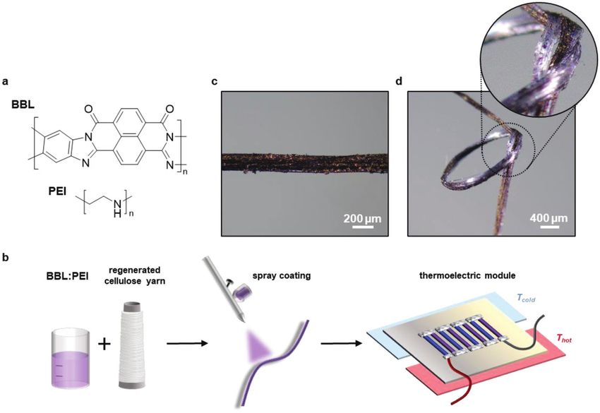
2199160x, 0, Downloaded from https://onlinelibrary.wiley.com/doi/10.1002/aelm.202201235 by Chalmers University Of Technology, Wiley Online Library on [27/02/2023]. See the Terms and Conditions (https://onlinelibrary.wiley.com/terms-and-conditions) on Wiley Online Library for rules of use; OA articles are governed by the applicable Creative Commons License
Research Article

                                                                                                                                www.advelectronicmat.de

Polymer-Based n-Type Yarn for Organic Thermoelectric
Textiles
Sozan Darabi, Chi-Yuan Yang, Zerui Li, Jun-Da Huang, Michael Hummel, Herbert Sixta,
Simone Fabiano, and Christian Müller*
                                                                                                antennas for communication.[6] E-textiles
A conjugated-polymer-based n-type yarn for thermoelectric textiles is pre-                      can be powered by equipping them with
sented. Thermoelectric textile devices are intriguing power sources for                         the ability to harvest energy on the spot via
wearable electronic devices. The use of yarns comprising conjugated poly-                       the integration of solar cells,[7,8] or piezo-
                                                                                                electric,[9,10] triboelectric,[11] and thermo-
mers is desirable because of their potentially superior mechanical proper-                      electric devices.[12–14] Thermoelectric textile
ties compared to other thermoelectric materials. While several examples of                      devices are intriguing because they would
p-type conducting yarns exist, there is a lack of polymer-based n-type yarns.                   allow to exploit ubiquitous local tempera-
Here, a regenerated cellulose yarn is spray-coated with an n-type conducting-                   ture gradients, for example, the difference
polymer-based ink composed of poly(benzimidazobenzophenanthroline)                              in temperature between skin and the sur-
                                                                                                roundings, separated by a garment.
(BBL) and poly(ethyleneimine) (PEI). The n-type yarns display a bulk elec-
                                                                                                   Thermoelectric devices convert heat
trical conductivity of 8 × 10⁻³ S cm−1 and Seebeck coefficient of −79 µV K−1.                   to electricity based on the Seebeck effect.
A promising level of air-stability for at least 13 days can be achieved by                      When a thermoelectric material experi-
applying an additional thermoplastic elastomer coating. A prototype in-plane                    ences a temperature gradient ΔT a poten-
thermoelectric textile, produced with the developed n-type yarns and p-type                     tial difference ΔV is generated across the
                                                                                                material according to ΔV = −αΔT, where
yarns, composed of poly(3,4-ethylenedioxythiophene):poly(styrenesulfonate)
                                                                                                α is the material-specific Seebeck coef-
(PEDOT:PSS)-coated regenerated cellulose, displays a stable device perfor-                      ficient which is positive for p-type and
mance in air for at least 4 days with an open-circuit voltage per temperature                   negative for n-type materials. Thermoelec-
difference of 1 mV °C−1. Evidently, polymer-based n-type yarns are a viable                     tric devices are composed of thermocou-
component for the construction of thermoelectric textile devices.                               ples, each one of them consisting of one
                                                                                                n-type and one p-type leg, which are con-
                                                                                                nected electrically in series but thermally
1. Introduction                                                      in parallel so that the voltage generated by the two legs is addi-
                                                                     tive. Each thermocouple only generates a small voltage, which
Textiles are a versatile platform for wearable electronics because   is insufficient to power an electronic device, and thus a large
they readily permit the placement of a multitude of devices in       number of these elements must be integrated. The open-circuit
close proximity to the user.[1,2] A wide range of electronic textile voltage Voc of a thermoelectric device is given by:
(e-textile) devices have been demonstrated, ranging from sensors
for health monitoring[3] to keyboards,[4] displays[5] and wearable   Voc = N element (α p − α n ) ∆T                                        (1)

S. Darabi, Z. Li, C. Müller                                                   C.-Y. Yang, J.-D. Huang, S. Fabiano
Department of Chemistry and Chemical Engineering                              Laboratory of Organic Electronics
Chalmers University of Technology                                             Department of Science and Technology
Göteborg 412 96, Sweden                                                       Linköping University
E-mail: christian.muller@chalmers.se                                          Norrköping 60174, Sweden
S. Darabi, C. Müller                                                          C.-Y. Yang, S. Fabiano
Wallenberg Wood Science Center                                                n-Ink AB
Chalmers University of Technology                                             Norrköping 60174, Sweden
Göteborg 412 96, Sweden                                                       Z. Li
      The ORCID identification number(s) for the author(s) of this article    College of Electrical Engineering
      can be found under https://doi.org/10.1002/aelm.202201235.              Sichuan University
                                                                              Chengdu 610065, China
© 2023 The Authors. Advanced Electronic Materials published by                M. Hummel, H. Sixta
Wiley-VCH GmbH. This is an open access article under the terms of the         Department of Bioproducts and Biosystems
Creative Commons Attribution License, which permits use, distribution         Aalto University
and reproduction in any medium, provided the original work is properly        Espoo 02150, Finland
cited.                                                                        S. Fabiano
                                                                              Wallenberg Wood Science Center
                                                                              Linköping University
DOI: 10.1002/aelm.202201235                                                   Norrköping 60174, Sweden

Adv. Electron. Mater. 2023, 2201235          2201235 (1 of 8)                © 2023 The Authors. Advanced Electronic Materials published by Wiley-VCH GmbH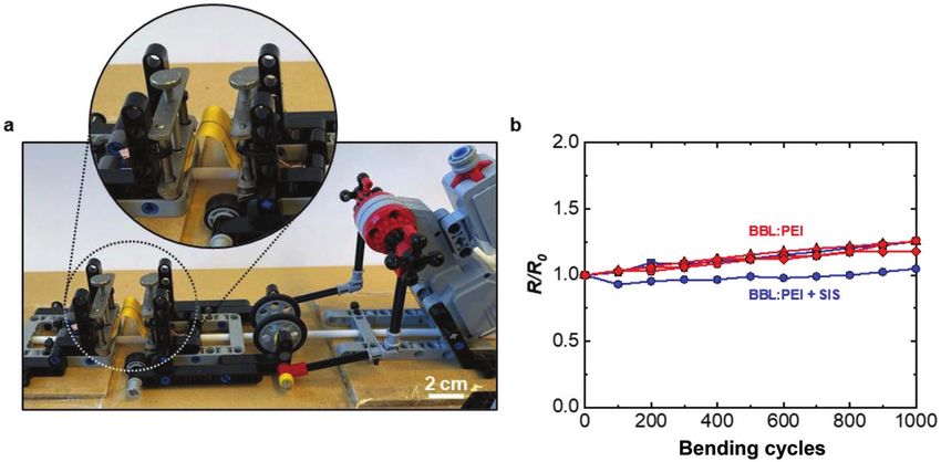
2199160x, 0, Downloaded from https://onlinelibrary.wiley.com/doi/10.1002/aelm.202201235 by Chalmers University Of Technology, Wiley Online Library on [27/02/2023]. See the Terms and Conditions (https://onlinelibrary.wiley.com/terms-and-conditions) on Wiley Online Library for rules of use; OA articles are governed by the applicable Creative Commons License
www.advancedsciencenews.com
                                                                                                                                               www.advelectronicmat.de
Table 1. Overview of previously reported n-type yarns/fibers and the electrical conductivity σ and Seebeck coefficient α of these materials.

                       Conducting material    Substrate yarn/fiber         Dopant             Manufacturing method       α [µV K−1]           σ [S cm−1]          Ref.
                                                          a)
Inorganic materials           Bi2Te3                 PAN                                        Electrospinning/            −176                  8               [19]
                                                                                               sputtering/twisting
                              Bi2Se3                                                            Thermal drawing             −92                  763              [31]

Carbon allotropes            PCBMb)                  cotton                                        Dip-coating             −283                1 × 10⁻²           [12]

                              CNTc)                                         PEId)                Direct spinning            −56                  7850             [25]

                              CNT                                        PEI/NaBH4                      –                   −58                  871              [28]

                              CNT                                            PEI                        –                   −69                  1408             [29]

                              CNT                                         Oleamine             Electrospray coating         −64                  ≈780             [13]
                                       e)                                            f)
                           CNT:PEG                                      [BMIM]PF6                 Wet-spinning              −49                  ≈175             [24]

                       SWCNTg): PVAh):PEI                                                         Gel extrusion             −48                7 × 10⁻³           [32]

                         SWCNT: PVDFi)                                       PEI                  Wet-spinning              −38                  1550             [33]

                         MWCNTj): PVPk)               PET                                          Dip-coating              −14                   1               [30]

                           Graphene:                                        PEIEl)            Hydrothermal process          −4.2                  11              [21]
                          PEDOT:PSSn)
                            Graphene                                        PEIE               Chemical reduction           −16                   10              [22]

Polymers                     BBL:PEI                cellulose                                     Spray-coating             −79                8 × 10⁻³        This work

a)PAN  = polyacrylonitrile; b)PCBM = [6,6]-phenyl-C61-butyric acid methyl ester; c)CNT = carbon nanotubes; d)PEI = polyethylenimine; e)PEG = polyethylene glycol; f)[BMIM]
PF6 = 1-butyl-3-methylimidazolium hexafluorophosphate; g)SWCNT = single-walled carbon nanotubes; h)PVA = poly(vinyl alcohol); i)PVDF = polyvinylidene fluoride; j)MWCNT =
multiwalled carbon nanotubes; k)PVP = poly(vinylpyrrolidone); l)PEIE = polyethyleneimine ethoxylate; n)PEDOT:PSS = poly(3,4-ethylenedioxythiophene):poly(styrenesulfonate).

where Nelement is the number of thermocouples and αp and αn                                of 0.3 µV K−1.[14] Due to health and environmental concerns
are the Seebeck coefficients of the p- and n-type leg, respectively.                       associated with the use of carbon nanomaterials it would be of
    Textile manufacturing processes are readily suitable for                               interest to develop polymer-based n-type yarns.
creating the complex patterns comprising a multitude of ther-                                 Here, we report the fabrication of polymer-based n-type
mocouples that make up thermoelectric devices. For example,                                yarns based on regenerated cellulose yarns, which were chosen
thermoelectric devices have been printed[15–17] or coated[18] onto                         as a substrate material because they offer sustainable produc-
an existing fabric or they have been incorporated into a textile                           tion processes from a variety of feedstocks.[34,35] As the con-
layer through weaving,[19] knitting,[19] or stitching of conducting                        ducting material poly(benzimidazobenzophenanthroline) (BBL)
fibers.[12] For the latter approach, which enables the creation of                         was selected, which was recently found to yield an electrical
textile devices from the bottom-up, electrically conducting fibers                         conductivity of up to σ = 8 S cm−1 when processed together
and yarns are needed. Several methods can be used to produce                               with poly(ethyleneimine) (PEI) from ethanol.[36] Regener-
conducting yarns such as coating or dyeing of an existing yarn                             ated cellulose yarns were spray-coated with an ethanol-based
and solution- or melt spinning of a conducting material into                               BBL:PEI ink resulting in n-type yarns with a bulk electrical con-
fibers, which can subsequently be twisted into a yarn.[20]                                 ductivity of σb = 8 × 10⁻³ S cm−1 (relative to the cross-sectional
    A number of different materials have been used to produce                              area of the entire coated cellulose yarn) and promising degree
p-type yarns, including inorganic materials,[19] graphene,[21,22]                          of air-stability. The ambient stability was further improved
carbon nanotubes,[23–25] and conducting polymers.[12,26,27] With                           by coating with an insulating thermoplastic elastomer layer,
regard to n-type yarns, however, there are only studies that                               which facilitated the fabrication of thermoelectric textile devices
employ Bi2Te3,[19] fullerenes,[12] graphene,[21,22] or carbon nano-                        by stitching the passivated BBL:PEI n-type yarns onto a wool
tubes[24,28] (Table 1). As a result, promising thermoelectric tex-                         fabric.
tile designs have been realized with, e.g., carbon nanotube-
based p- and n-type yarns.[13,24,29] Instead, n-type conducting
polymers have not yet been reported for the fabrication of con-                            2. Results and Discussion
ducting yarns, likely due to their insufficient air stability. The
lack of polymer-based n-type yarns currently limits the type of                            In a first set of experiments, we compared dip-coating and
architectures that can be realized since conducting polymers                               spray-coating of regenerated cellulose yarns with an ethanol-
tend to offer advantages in terms of cost-effective processing                             based BBL:PEI ink (1:1 weight ratio; see Figure 1a for chemical
from solution as well as a high degree of mechanical flexibility.                          structures). Dip-coating involved immersing the yarn in the
Polymer-based textile thermoelectric devices that have been                                ink four times while spray-coating was performed with a spray
reported consist of p-type yarns that are either combined with                             gun (Figure 1b), coating approximately 1 cm-long segments of
carbon nanotube-based n-type yarns,[30] or a conducting yarn                               the yarn at a time (see Experimental Section for details). We
such as silver-plated yarns with a very low Seebeck coefficient                            did not dry the yarns subsequent to the coating step because

Adv. Electron. Mater. 2023, 2201235                2201235 (2 of 8)                       © 2023 The Authors. Advanced Electronic Materials published by Wiley-VCH GmbH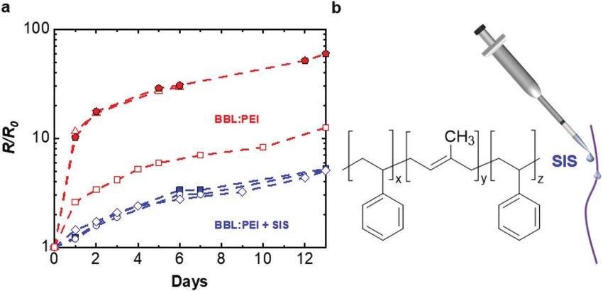
2199160x, 0, Downloaded from https://onlinelibrary.wiley.com/doi/10.1002/aelm.202201235 by Chalmers University Of Technology, Wiley Online Library on [27/02/2023]. See the Terms and Conditions (https://onlinelibrary.wiley.com/terms-and-conditions) on Wiley Online Library for rules of use; OA articles are governed by the applicable Creative Commons License
www.advancedsciencenews.com
                                                                                                                              www.advelectronicmat.de

Figure 1. a) Chemical structures of poly(benzimidazobenzophenanthroline) (BBL) and poly(ethyleneimine) (PEI). b) Schematic of the preparation of
electrically conducting n-type yarn through spray coating and integration of the yarn into a thermoelectric device. c,d) Optical microscopy images of
the surface of a representative BBL:PEI coated cellulose yarn and the same yarn forming a loose knot.

ethanol readily evaporates. However, we thermally treated the               can be anticipated to predominately feature hydroxy groups,
yarns later on under an inert atmosphere (140 °C for 2 h under              which may hydrogen-bond to the secondary amines of PEI,
nitrogen; see Experimental Section for details) since polaron               resulting in good adhesion between BBL:PEI and the cellulose
formation within BBL:PEI is thermally activated.[36] The n-type             yarn substrate. SEM images of the yarn surface and cross-sec-
electrical conductivity of the BBL:PEI mixture stems from a                 tion reveal a discontinuous outer coating that surrounds the
thermally activated electron transfer from the amine-based PEI              yarn (Figure 2a–c). It appears that the conducting material,
to the conjugated BBL polymer backbone. The positive charges                i.e., BBL:PEI, is present on the surface of some of the indi-
on PEI balance the negatively charged polarons on BBL,                      vidual filaments as indicated by the lack of charging artifacts
yielding an n-doped all-polymer blend.                                      (Figure 2d). However, the coverage of individual yarns is likely
   The quality of the applied BBL:PEI coatings from the two                 irregular since charging artifacts also appear in SEM images
processes were compared by measuring the electrical resist-                 recorded along the long-axis of the yarn (Figure 2a,b).
ance of the coated yarns (see Figure S1a–c, Supporting Infor-                  We investigated the electrical properties of spray-coated
mation, for images of the samples). Dip-coated yarns featured               yarns by measuring their bulk electrical conductivity in two-
intermittent sections with a high resistivity, indicating an inho-          point configuration according to:
mogeneous coating (Figure S1d, Supporting Information). In
contrast, spray-coated yarns were electrically conducting along                             L
                                                                             σ b = R −1 ×                                                           (2)
their entire length, and therefore we chose to focus on the latter                          A
type of yarn throughout the remainder of this study.
   Optical and scanning electron microscopy (SEM) were                      where L is the length of the measured yarn segment, A the total
used to assess the quality of the BBL:PEI coating of spray-                 cross-sectional area of the yarn (calculated using the yarn diam-
coated yarns in more detail. Optical micrographs indicate that              eter, which includes the insulating cellulose material as well
the polymers cover the entire yarn and do not detach upon                   as voids in between filaments), and R the measured resistance
bending (Figure 1c,d and Figure S2, Supporting Informa-                     (see Experimental Section for details). We obtained a value of
tion). The surface of the here used regenerated cellulose yarns             about σb = (8 ± 2) × 10−3 S cm−1 for the here studied n-type

Adv. Electron. Mater. 2023, 2201235        2201235 (3 of 8)                © 2023 The Authors. Advanced Electronic Materials published by Wiley-VCH GmbH
2199160x, 0, Downloaded from https://onlinelibrary.wiley.com/doi/10.1002/aelm.202201235 by Chalmers University Of Technology, Wiley Online Library on [27/02/2023]. See the Terms and Conditions (https://onlinelibrary.wiley.com/terms-and-conditions) on Wiley Online Library for rules of use; OA articles are governed by the applicable Creative Commons License
www.advancedsciencenews.com
www.advelectronicmat.de
Figure 2. a–d) Scanning electron microscopy (SEM) images of the surface of a BBL:PEI coated yarn (a,b), the cross-section of a BBL:PEI-coated yarn
(c), and an individual filament (d).
yarns. The linear density of neat yarns was 9.5 tex while the ambient conditions and increased in absolute value from −79
BBL:PEI coated yarn had a linear density of 9.8 tex (measured to −213 µV K−1, indicating that the material became less doped
by weighing sections of the yarns), which indicates that ≈3 wt% (Figure S3, Supporting Information). Therefore, we applied an
of the coated yarn consisted of BBL:PEI. We thus estimate an insulating barrier layer composed of the elastomer polystyrene-
effective conductivity for the BBL:PEI coating of 0.6 S cm−1 b-polyisoprene-b-polystyrene (SIS) (Figure 3b), leaving the yarn
(assuming a density of 1 g cm−3) by comparing the cross-sec- ends uncoated to facilitate points for electrical contact. The
tional area of the yarn to the area of the BBL:PEI coating. The addition of a SIS layer led to an eightfold decrease of the initial
conductivity of the BBL:PEI coating is somewhat lower than the conductivity of the yarn to 0.001 S cm−1, which we assign to air
value of σ = (3.1 ± 0.1) S cm−1 measured for a reference BBL:PEI exposure during the SIS coating step. The initial resistance of
layer spray-coated onto a glass substrate. We argue that not the 4 to 7 cm-long sections of the n-type yarns only increased
every part of the BBL:PEI coating within the prepared yarn is five times after 13 days at ambient conditions, indicating
continuous, thus reducing the overall electrical conductivity. improved ambient electrical stability (Figure 3a). We attribute
Hence, the thermoelectric properties of the prepared n-type the remaining change in electrical resistance to the unpro-
yarns could likely be improved by increasing the quality of the tected yarn ends. BBL:PEI coated yarn stored under inert condi-
BBL:PEI coating. We also determined the Seebeck coefficient tions displayed a ≈5 times increase in resistance after 14 days
of as-prepared BBL:PEI coated yarns and obtained a value of (Figure S4, Supporting Information), confirming that the here
αn = −79 µV K−1, which is similar to a value of (−115 ± 9) µV K−1 studied n-type conductor is fairly stable once protected from air.
measured for an as-prepared and annealed reference BBL:PEI The resilience of the n-type yarn toward deformation was
film (power factor α2σ = 0.4 µW m−1 K−2 for the yarn coating investigated by performing bending tests. The yarn was bent
and 4 µW m−1 K−2 for the reference film). 1000 times (bending radius = 4.2 mm) (Figure 4a) and the elec-
We evaluated the electrical stability of yarns stored at trical resistance was measured after every 100 bending cycles
ambient conditions by repeatedly measuring the electrical using a 2-point configuration. The electrical resistance of the
resistance of coated yarns over the course of 2 weeks. The elec- BBL:PEI coated yarn increased by about 20% irrespective of the
trical resistance of BBL:PEI coated yarn had increased about 10 presence of the additional SIS coating (Figure 4b), which sug-
to 60 times after 13 days (Figure 3a). The Seebeck coefficient gests that the here studied materials feature a promising degree
also varied during a repeated measurement period of 12 days at of robustness that facilitates simple textile manufacturing
Adv. Electron. Mater. 2023, 2201235 2201235 (4 of 8) © 2023 The Authors. Advanced Electronic Materials published by Wiley-VCH GmbH2199160x, 0, Downloaded from https://onlinelibrary.wiley.com/doi/10.1002/aelm.202201235 by Chalmers University Of Technology, Wiley Online Library on [27/02/2023]. See the Terms and Conditions (https://onlinelibrary.wiley.com/terms-and-conditions) on Wiley Online Library for rules of use; OA articles are governed by the applicable Creative Commons License
www.advancedsciencenews.com
www.advelectronicmat.de
Figure 3. a) Electrical stability of BBL:PEI coated yarns stored at ambient conditions without (red) or with a SIS layer (blue) expressed as the ratio of
electrical resistance R divided by the initial resistance R0. The various symbols indicate different samples. R0/L = 4.1, 8.8, and 10.5 MΩ cm−1 for the SIS
coated yarns, dried for 24 h at ambient conditions before electrical characterization; R0/L = 1.7, 1.1, and 4.2 MΩ cm−1 for as-prepared BBL:PEI yarns. b)
Chemical structure of SIS and schematic of the process used to coat the conducting BBL:PEI yarn with a protective SIS layer.
methods such as stitching. Tensile deformation of BBL:PEI and device fabrication) and one p-type leg made with two
spray-coated yarn revealed a Young's modulus of (3.3 ± 0.5) PEDOT:PSS coated cellulose yarns with σp = 33 S cm−1 and
GPa and strain at break of (5.1 ± 0.9)% (Figure S5, Supporting αp = 14 µV K−1 (Figure S7, Supporting Information), which we
Information). have described previously.[37] The device had an internal resist-
An in-plane textile thermoelectric device was fabricated by ance of Rin = 180 MΩ.
stitching yarns onto a felted wool fabric to illustrate that the The performance of the device was assessed by placing the
BBL:PEI n-type yarn can be used for e-textile applications. wool felt with one end on a hot plate while the other end was
The device fabrication and characterization were done at kept at ambient temperature (Figure 5b,c). The open-circuit
ambient conditions. The device consisted of four thermocou- voltage Voc increased linearly with the temperature difference
ples (Figure 5a), each one comprising one n-type leg made with between the hot and cold side of the device ΔT = Thot − Tcold
three BBL:PEI/SIS coated cellulose yarns with σn = 0.001 S cm−1 with a slope of Voc/ΔT = 1.0 mV °C−1. The device consisted of
(value from 7 cm yarn section dried at ambient conditions post four n–p thermocouples and thus the generated voltage scales
SIS coating, which differs from the yarn used in the device) according to:
and αn = −272 µV K−1 (see Figure S6, Supporting Information,
the change is attributed to air exposure during SIS coating Voc / ∆T = 4 × (α p − α n ) (3)
Figure 4. a) Photograph of the custom-built LEGO device used for bending tests with a mounted yarn sample. b) Electrical resistance R divided by the
initial resistance R0 measured after every 100 cycles during a total of 1000 bending cycles of BBL:PEI coated yarn (red) and BBL:PEI/SIS coated yarn
(blue). The various symbols indicate different samples.
Adv. Electron. Mater. 2023, 2201235 2201235 (5 of 8) © 2023 The Authors. Advanced Electronic Materials published by Wiley-VCH GmbH2199160x, 0, Downloaded from https://onlinelibrary.wiley.com/doi/10.1002/aelm.202201235 by Chalmers University Of Technology, Wiley Online Library on [27/02/2023]. See the Terms and Conditions (https://onlinelibrary.wiley.com/terms-and-conditions) on Wiley Online Library for rules of use; OA articles are governed by the applicable Creative Commons License
www.advancedsciencenews.com
www.advelectronicmat.de
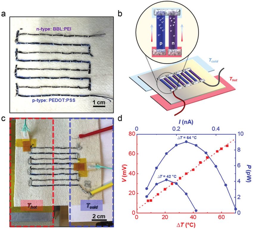
Figure 5. a) An in-plane thermoelectric textile generator stitched onto a felted wool fabric using BBL:PEI/SIS coated cellulose yarn (three yarns per
n-type leg) and a PEDOT:PSS coated cellulose yarn (two yarns per p-type leg) that together form four n/p thermocouples. b) Schematic showing a close-
up of a single thermocouple with the blue yarn representing the p-type PEDOT:PSS coated yarn while the purple yarn represents the n-type BBL:PEI/
SIS coated yarn. The light blue area illustrates the heat sink (cold side) while the red area represents the heat source (hot side). c) The thermoelectric
textile generator with the four n/p thermocouples electrically connected with stretchable silver paint and placed onto a heating source at temperature
Tnot (red) and a cold side that was kept at ambient temperature Tcold (blue). d) The recorded open-circuit voltage Voc measured for different temperature
gradients ΔT = Thot − Tcold (red) with the output power P as a function of load current I at ΔT = 42 °C or 64 °C (blue).
which yields a value of Voc/ΔT = 1.1 mV °C−1, in good agree- compared with many other polymer-based n-type conductors.
ment with the measured value. We measured a Voc = 68 mV In addition, the textile thermoelectric device was subjected to
for ΔT = 64 °C and determined the power output for a series repeated bending (6 months after device fabrication; the device
of load currents (Figure 5d), which yielded a maximum power was stored in a glove box) during which the Seebeck coeffi-
output of Pmax = 9 pW, in reasonable agreement with a value of cient of one if its n-type legs was monitored. The initial value
6.4 pW, predicted by using the measured values for Voc and Rin: of αn = −380 µV K−1 changed to −319 µV K−1 after 400 bending
cycles (Figures S9 and S10, Supporting Information; the device
Voc2 was exposed to air for 8 h).
Pmax = (4)
4Rin
We assign the differences in measured and predicted values 3. Conclusions
to the variation in Seebeck coefficient of BBL:PEI coated yarns
upon ageing (see Figure S3, Supporting Information). The per- Spray coating of a regenerated cellulose yarn with BBL:PEI
formance of the thermoelectric textile device was monitored ink resulted in an n-type yarn with robust mechanical prop-
over the course of several days. Characterization was done at erties. The n-type yarn displayed an electrical conductivity of
ambient conditions, but the device was stored in a glovebox σ = (8 ± 2) × 10−3 S cm−1 and a Seebeck coefficient of α =
between measurements. After 4 days the Voc/ΔT had changed −79 µV K−1. Coating of the BBL:PEI coated yarn with an addi-
from 1.0 to 1.1 mV °C−1 and the maximum power output had tional insulating barrier layer composed of the elastomer SIS
decreased from 4.2 to 3.5 pW at ΔT = 42 °C (Figure S8, Sup- allowed to significantly improve the electrical stability of the
porting Information), confirming that the BBL:PEI coating n-type yarn at ambient conditions. The utility of the n-type yarn
of the here studied n-type yarn displays improved air-stability was illustrated by the fabrication of an in-plane thermoelectric
Adv. Electron. Mater. 2023, 2201235 2201235 (6 of 8) © 2023 The Authors. Advanced Electronic Materials published by Wiley-VCH GmbH2199160x, 0, Downloaded from https://onlinelibrary.wiley.com/doi/10.1002/aelm.202201235 by Chalmers University Of Technology, Wiley Online Library on [27/02/2023]. See the Terms and Conditions (https://onlinelibrary.wiley.com/terms-and-conditions) on Wiley Online Library for rules of use; OA articles are governed by the applicable Creative Commons License
www.advancedsciencenews.com
www.advelectronicmat.de
textile device with a stable performance for at least 4 days, with and stretchable silver paint (PE874 from DuPont), cured at 100 °C for
an open-circuit voltage per temperature difference of about 20 min, was used to improve the electrical connection between legs.
1 mV °C−1. We conclude that the use of polymer-based n-type The textile device was placed with one side on a hot plate (HP60, Torrey
Pines Scientific Inc.) and the other side on a stage that was kept at
yarns has potential for the realization of robust and stable ther- room temperature. K-type thermocouples were attached to both sides to
moelectric textile devices. It can be anticipated that the here record the temperature difference using a cDAW 9174 instrument from
presented results will stimulate further studies that ultimately National Instruments with an internal temperature reference. The hot
lead to highly conducting polymer-based n-type yarns. side of the device was kept in place with a weight of about 1 kg. The open-
circuit voltage was measured with a Keithley 2400 source measure unit.
Furthermore, the instrument was used as a variable load and the output
voltage was measured to obtain the maximum power that the device
4. Experimental Section could produce. Additionally, the Seebeck coefficient of an n-type leg was
Materials: Ioncell-F yarn and the BBL:PEI ink were prepared according determined by measuring the voltage for different temperature gradients
to previously reported procedures.[36,38] Polystyrene-b-polyisoprene-b- (between hot plate and room temperature) using a Keithley 2400 source
polystyrene (SIS) (styrene 22 wt%) was obtained from Sigma–Aldrich, measure unit.
toluene and ethylene glycol from Fisher Scientific, dimethyl sulfoxide
(DMSO) from VWR, and PEDOT:PSS aqueous dispersion from Heraeus
(1.1–1.3 wt% solid content; Clevios PH1000). Silver paints for electrical Supporting Information
characterization and textile device fabrication (PE874) were purchased
from Agar Scientific and DuPont, respectively. Supporting Information is available from the Wiley Online Library or
Yarn Coating: PEDOT:PSS coated yarns were prepared according from the author.
to a previously published procedure.[37] To fabricate n-type yarns, the
regenerated cellulose yarn was fastened on a spool while BBL:PEI ink
(1 g L−1), dispersed in ethanol, was repeatedly spray-coated onto the Acknowledgements
yarns at ambient conditions using a standard HD-130 airbrush (0.3 mm)
with 2 bars of atomization air pressure, followed by annealing inside a The authors gratefully acknowledge financial support from the
nitrogen-filled glovebox by placing the yarn on a heating plate at 140 °C Wallenberg Wood Science Center (WWSC). This project was in part
for 2 h. BBL:PEI thin films were also produced through spray-coating. performed at the Chalmers Materials Analysis Laboratory (CMAL). The
The annealed BBL:PEI coated yarn was coated with SIS in toluene authors thank Anders Mårtensson for his assistance with the SEM
(100 g L−1) by pipetting droplets onto the yarn, except for the yarn ends, measurements.
at ambient conditions. The SIS layer was dried for 24 h at ambient
conditions before electrical characterization or in a glovebox before
textile device fabrication. Conflict of Interest
Electrical Characterization: The electrical resistance of 0.8 cm-long
sections of the yarns, placed on a glass slide and contacted with silver The authors declare no conflict of interest.
paint, was determined in 2-point configuration using a Keithley 2400
source measure unit. A custom-built LEGO device was used to perform
repeated bending of the yarns (≈7 cm-long segments), attached to a
paper frame and contacted with silver paint and copper tape, with a Data Availability Statement
bending radius of ≈4.2 mm. The Seebeck coefficient of 5 mm-long yarn
The data that support the findings of this study are available from the
sections, contacted with silver paint on either end, was measured at
corresponding author upon reasonable request.
ambient conditions with a SB1000 instrument and a K2000 temperature
controller from MMR Technologies. A constantan wire was used as the
reference.
The BBL:PEI thin films were characterized while inside the glovebox Keywords
and the Seebeck coefficient as well as the electrical conductivity were
measured according to previously reported procedures.[36] electrically conducting regenerated cellulose yarn, electronic textiles
Optical Microscopy: The diameter of the yarns was determined with a (e-textiles), organic thermoelectrics, poly(benzimidazobenzophenanthro
Carl Zeiss A1 optical microscope in bright field transmission mode and line) (BBL), thermoelectric textile devices
images of the knotted yarn were recorded with a Carl Zeiss Stemi 508
stereo microscope. Received: November 13, 2022
Scanning Electron Microscopy: Fracture surfaces were prepared by Revised: December 19, 2022
cutting yarns immersed in liquid nitrogen. SEM images were recorded Published online:
with a JSM-7800F prime instrument equipped with a secondary electron
detector at an acceleration voltage of 3 kV. The BBL:PEI coated yarns
were annealed, as previously explained, and later cut with scissors while
immersed in liquid nitrogen. Samples were not sputtered.
[1] G. Chen, X. Xiao, X. Zhao, T. Tat, M. Bick, J. Chen, Chem. Rev. 2022,
Tensile Deformation: Stress–strain curves were recorded with a
122, 3259.
Q800 dynamic mechanical analyzer (DMA) from TA instruments. Yarn
[2] K. Du, R. Lin, L. Yin, J. S. Ho, J. Wang, C. T. Lim, iScience 2022, 25,
sections were mounted by first fixating either end with glue (Loctite
Super Glue Precision) between two pieces of paper to prevent the yarn 104174.
from slipping, which were then held in place by a pair of film tension [3] S. Takamatsu, T. Lonjaret, D. Crisp, J.-M. Badier, G. G. Malliaras,
clamps. A pre-load force of 1 mN was applied and a ramp force rate of E. Ismailova, Sci. Rep. 2015, 5, 15003.
10 to 18 N min−1 was used. [4] S. Takamatsu, T. Lonjaret, E. Ismailova, A. Masuda, T. Itoh,
Textile Device Fabrication and Characterization: A textile thermoelectric G. G. Malliaras, Adv. Mater. 2016, 28, 4485.
generator was produced by stitching p- and n-type yarns onto a felted [5] S. Sinha, R. Daniels, O. Yassin, M. Baczkowski, M. Tefferi,
wool fabric from Harry Hedgren AB (Wadmal, 3.2 g dm−2, ≈1 mm thick). A. Deshmukh, Y. Cao, G. Sotzing, Adv. Mater. Technol. 2022, 7,
Each n- and p-type leg consisted of three and two yarns, respectively, 2100548.
Adv. Electron. Mater. 2023, 2201235 2201235 (7 of 8) © 2023 The Authors. Advanced Electronic Materials published by Wiley-VCH GmbH2199160x, 0, Downloaded from https://onlinelibrary.wiley.com/doi/10.1002/aelm.202201235 by Chalmers University Of Technology, Wiley Online Library on [27/02/2023]. See the Terms and Conditions (https://onlinelibrary.wiley.com/terms-and-conditions) on Wiley Online Library for rules of use; OA articles are governed by the applicable Creative Commons License
www.advancedsciencenews.com
www.advelectronicmat.de
[6] Z. Li, S. K. Sinha, G. M. Treich, Y. Wang, Q. Yang, A. A. Deshmukh, [24] M. Ito, T. Koizumi, H. Kojima, T. Saito, M. Nakamura, J. Mater.
G. A. Sotzing, Y. Cao, J. Mater. Chem. C 2020, 8, 5662. Chem. A 2017, 5, 12068.
[7] J. Chen, Y. Huang, N. Zhang, H. Zou, R. Liu, C. Tao, X. Fan, [25] J. Choi, Y. Jung, S. J. Yang, J. Y. Oh, J. Oh, K. Jo, J. G. Son,
Z. L. Wang, Nat. Energy 2016, 1, 16138. S. E. Moon, C. R. Park, H. Kim, ACS Nano 2017, 11, 7608.
[8] M. Hatamvand, E. Kamrani, M. Lira-Cantú, M. Madsen, B. R. Patil, [26] T. Bashir, M. Skrifvars, N.-K. Persson, Polym. Adv. Technol. 2011, 22,
P. Vivo, M. S. Mehmood, A. Numan, I. Ahmed, Y. Zhan, Nano 2214.
Energy 2020, 71, 104609. [27] A. Lund, S. Darabi, S. Hultmark, J. D. Ryan, B. Andersson, A. Ström,
[9] N. Soin, T. H. Shah, S. C. Anand, J. Geng, W. Pornwannachai, C. Müller, Adv. Mater. Technol. 2018, 3, 1800251.
P. Mandal, D. Reid, S. Sharma, R. L. Hadimani, D. V. Bayramol, [28] X. Lan, T. Wang, C. Liu, P. Liu, J. Xu, X. Liu, Y. Du, F. Jiang, Compos.
E. Siores, Energy Environ. Sci. 2014, 7, 1670. Sci. Technol. 2019, 182, 107767.
[10] A. Lund, K. Rundqvist, E. Nilsson, L. Yu, B. Hagström, C. Müller, [29] Y. Zheng, Q. Zhang, W. Jin, Y. Jing, X. Chen, X. Han, Q. Bao, Y. Liu,
npj Flexible Electron. 2018, 2, 9. X. Wang, S. Wang, Y. Qiu, C.-a. Di, K. Zhang, J. Mater. Chem. A
[11] X. Pu, L. Li, H. Song, C. Du, Z. Zhao, C. Jiang, G. Cao, W. Hu, 2020, 8, 2984.
Z. L. Wang, Adv. Mater. 2015, 27, 2472. [30] J. D. Ryan, A. Lund, A. I. Hofmann, R. Kroon, R. Sarabia-Riquelme,
[12] J. Pope, C. Lekakou, Smart Mater. Struct. 2019, 28, 095006. M. C. Weisenberger, C. Müller, ACS Appl. Energy Mater. 2018, 1,
[13] T. Sun, B. Zhou, Q. Zheng, L. Wang, W. Jiang, G. J. Snyder, Nat. 2934.
Commun. 2020, 11, 572. [31] T. Zhang, K. Li, J. Zhang, M. Chen, Z. Wang, S. Ma, N. Zhang,
[14] A. Lund, Y. Tian, S. Darabi, C. Müller, J. Power Sources 2020, 480, L. Wei, Nano Energy 2017, 41, 35.
228836. [32] T. Ding, K. H. Chan, Y. Zhou, X.-Q. Wang, Y. Cheng, T. Li, G. W. Ho,
[15] H. M. Elmoughni, A. K. Menon, R. M. W. Wolfe, S. K. Yee, Adv. Nat. Commun. 2020, 11, 6006.
Mater. Technol. 2019, 4, 1800708. [33] J.-Y. Kim, J.-H. Mo, Y. H. Kang, S. Y. Cho, K.-S. Jang, Nanoscale 2018,
[16] S. J. Kim, J. H. We, B. J. Cho, Energy Environ. Sci. 2014, 7, 1959. 10, 19766.
[17] L. K. Allison, T. L. Andrew, Adv. Mater. Technol. 2019, 4, 1800615. [34] H. Sixta, A. Michud, L. Hauru, S. Asaadi, Y. Ma, A. W. T. King,
[18] K. Kirihara, Q. Wei, M. Mukaida, T. Ishida, Synth. Met. 2017, 225, 41. I. Kilpeläinen, M. Hummel, Nord. Pulp Pap. Res. J. 2015, 30, 43.
[19] J. A. Lee, A. E. Aliev, J. S. Bykova, M. J. de Andrade, D. Kim, [35] Y. Ma, M. Hummel, M. Määttänen, A. Särkilahti, A. Harlin, H. Sixta,
H. J. Sim, X. Lepró, A. A. Zakhidov, J.-B. Lee, G. M. Spinks, S. Roth, Green Chem. 2016, 18, 858.
S. J. Kim, R. H. Baughman, Adv. Mater. 2016, 28, 5038. [36] C.-Y. Yang, M.-A. Stoeckel, T.-P. Ruoko, H.-Y. Wu, X. Liu, N. B. Kolhe,
[20] A. Lund, N. M. van der Velden, N.-K. Persson, M. M. Hamedi, Z. Wu, Y. Puttisong, C. Musumeci, M. Massetti, H. Sun, K. Xu,
C. Müller, Mater. Sci. Eng., R 2018, 126, 1. D. Tu, W. M. Chen, H. Y. Woo, M. Fahlman, S. A. Jenekhe,
[21] J. Liu, G. Liu, J. Xu, C. Liu, W. Zhou, P. Liu, G. Nie, X. Duan, F. Jiang, M. Berggren, S. Fabiano, Nat. Commun. 2021, 12, 2354.
ACS Appl. Energy Mater. 2020, 3, 6165. [37] S. Darabi, M. Hummel, S. Rantasalo, M. Rissanen, I. Öberg
[22] Y. Lin, J. Liu, X. Wang, J. Xu, P. Liu, G. Nie, C. Liu, F. Jiang, Compos. Månsson, H. Hilke, B. Hwang, M. Skrifvars, M. M. Hamedi,
Commun. 2019, 16, 79. H. Sixta, A. Lund, C. Müller, ACS Appl. Mater. Interfaces 2020, 12,
[23] N. Komatsu, Y. Ichinose, O. S. Dewey, L. W. Taylor, M. A. Trafford, 56403.
Y. Yomogida, G. Wehmeyer, M. Pasquali, K. Yanagi, J. Kono, Nat. [38] S. Asaadi, M. Hummel, P. Ahvenainen, M. Gubitosi, U. Olsson,
Commun. 2021, 12, 4931. H. Sixta, Carbohydr. Polym. 2018, 181, 893.
Adv. Electron. Mater. 2023, 2201235 2201235 (8 of 8) © 2023 The Authors. Advanced Electronic Materials published by Wiley-VCH GmbHYou can also read