PJM Generation Interconnection Request Queue Position AD2-213 "East Flemington-Lebanon 34.5 kV" - Revised PJM Generator Interconnection Facility ...
←
→
Page content transcription
If your browser does not render page correctly, please read the page content below
Revised
     PJM Generator Interconnection

         Facility Study Report

                Related to:
PJM Generation Interconnection Request
      Queue Position AD2-213
  “East Flemington-Lebanon 34.5 kV”

                                 April 2021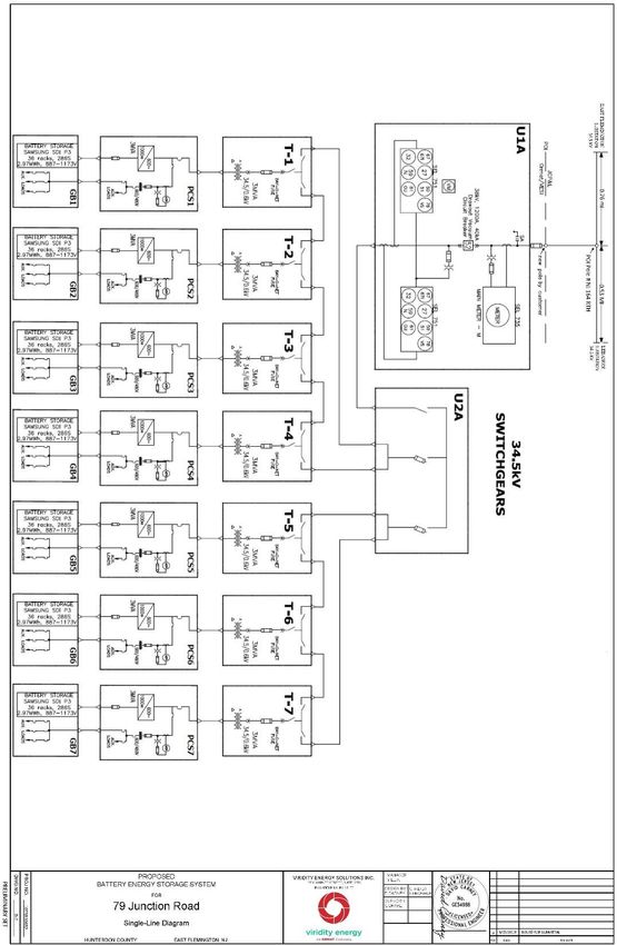
PJM Queue AD2-213 Facility Study

Table of Contents
   Preface .................................................................................................................................................................................. 3
   A. Transmission Owner Facilities Study Summary ................................................................................................ 3
       1. Description of Project ..................................................................................................................................... 3
       2. Amendments to the System Impact Study or System Impact Study Results .................................................. 3
       3. Revisions to December 2020 Facilities Study Report………………………………………………………..3
       4. Interconnection Customer’s Milestone Schedule ........................................................................................... 3
       5. Customer’s Scope of Work ............................................................................................................................. 4
       6. Description of Facilities Included in the Facilities Study ............................................................................... 4
       7. Total Cost of Transmission Owner Facilities Included in the Facilities Study............................................... 5
       8. Summary of the Schedule for Completion of Work for the Facilities Study .................................................. 5
   B. Transmission Owner Facilities Study Results .................................................................................................... 5
       1.        Transmission Lines –New ......................................................................................................................... 5
       2.        Transmission Lines – Upgrade .................................................................................................................. 6
       3.        Substation/Switchyard Facility Upgrades ................................................................................................. 7
       4.        Telecommunications Facilities – Upgrades............................................................................................... 7
       5.        Metering & Communications .................................................................................................................... 7
       6.        Environmental, Real Estate and Permitting............................................................................................... 7
       7.        Summary of Results of Study .................................................................................................................... 8
       9.        Schedules and Assumptions .................................................................................................................... 10
   Attachment A: Protection Scope........................................................................................................................... 12
   Attachment B: Single Line Diagram .................................................................................................................... 15
   Atttachment C: TO Single Line Diagram ............................................................................................................. 16
   Attachment C: Proposed Project Location............................................................................................................ 17
   Attachment D: Generation Connection Requirements ........................................................................................ 19

                                                                                                                                                                            Page | 2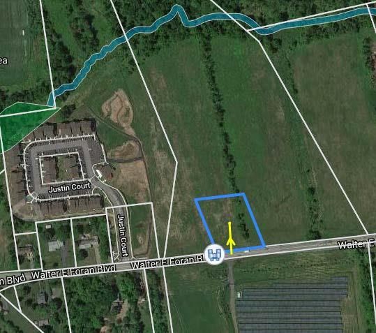
PJM Queue AD2-213 Facility Study
Preface
The intent of the Facility Study is to determine a plan, with approximate cost and construction time estimates, to
connect the subject generation interconnection project to the PJM network at a location specified by the
Interconnection Customer. As a requirement for interconnection, the Interconnection Customer may be responsible
for the cost of constructing: Network Upgrades, which are facility additions, or upgrades to existing facilities, that are
needed to maintain the reliability of the PJM system. All facilities required for interconnection of a generation
interconnection project must be designed to meet the technical specifications (on PJM web site) for the appropriate
transmission owner.
In some instances, an Interconnection Customer may not be responsible for 100% of the identified network upgrade
cost because other transmission network uses, e.g. another generation interconnection or merchant transmission
upgrade, may also contribute to the need for the same network reinforcement.
The Facility Study estimates attempt to identify the estimated time required to obtain property rights and permits for
construction of the required facilities. The project developer is responsible for the right-of-way, real estate, and
construction permit issues. For properties currently owned by Transmission Owners, the costs may be included in the
study.
A. Transmission Owner Facilities Study Summary
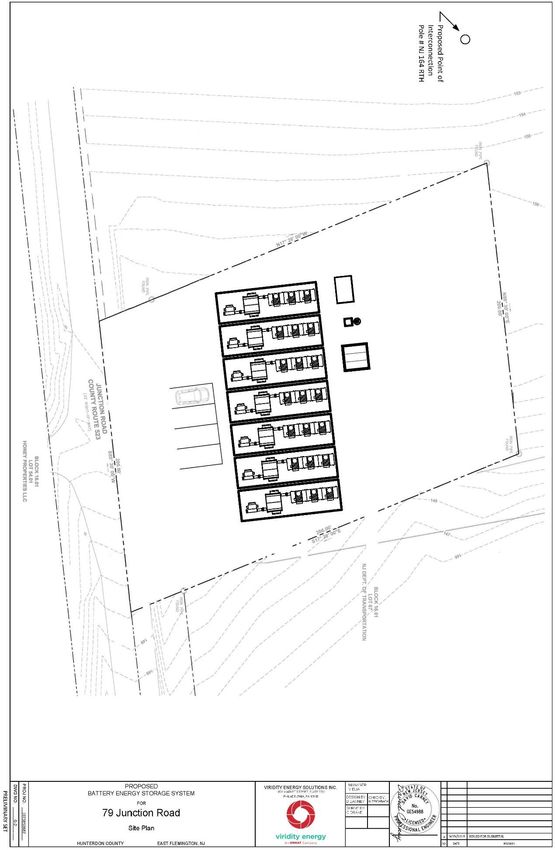
1. Description of Project
Ftera Energy APD Flemington LLC, (hereinafter referred to as IC) has proposed the addition of a new battery storage
generating facility for AD2-213 which will have a total capability of 20 MW with 0 MW of this output being
recognized by PJM as capacity.
This project is located at 79 Junction Road, Flemington, New Jersey, 08822. The generation facility will interconnect
with Jersey Central Power & Light (JCPL) a FirstEnergy Company (FE) hereinafter referred to as "Transmission
Owner" (TO), by tapping the Flemington-Lebanon 34.5 kV line at a point located approximately 0.53 miles from the
Lebanon substation and 0.76 miles from East Flemington substation.
2. Amendments to the System Impact Study or System Impact Study Results
The System Impact Study indicated that the GSU must have a grounded wye connection on the high (utility) side and
a delta connection on the low (generator) side. The protection requirements have been revised and require a delta or
ungrounded wye connection on the high (utility) side.
3. Revisions to December 2020 Facilities Study Report
The Facilities Study has been revised to reflect the updated milestone schedule as shown in Section 4.
4. Interconnection Customer’s Milestone Schedule
The planned in-service date, as requested by the IC is August 30, 2022. The planned initial back-feed date is June
15, 2022.
Page | 3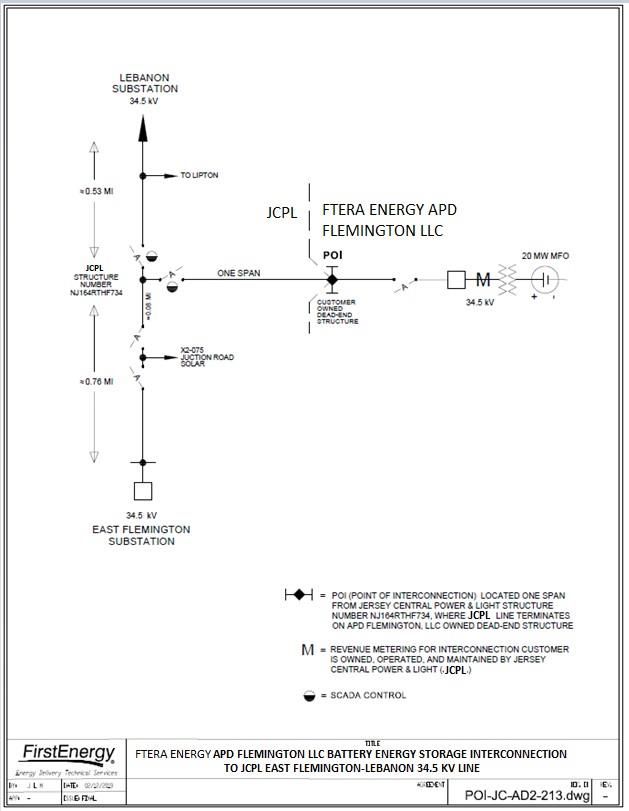
PJM Queue AD2-213 Facility Study
Transmission Owner’s Assumed Milestone Schedule:
06/15/2022 Initial Back-feed through Project Substation Date
08/30/2022 Project Commercial Operation Date
5. Customer’s Scope of Work
Developer will construct photovoltaic facilities, generation step-up (GSU) transformer(s), 34.5 kV generator Lead
Line, and connect to the Point of Interconnection.
Point of Interconnection (POI): The point where Developer’s 34.5 kV generator Lead Line terminates on the IC’s
newly installed 34.5 kV pole. (Ref: Figure 2).
Developer is required to own, install, and maintain a fully-rated, fault-interrupting circuit breaker on the high-side of
the GSU transformer with revenue metering equipment between the collector bus and the incoming generator lead
line. Transmission side (34.5kV) of the connecting transformer shall be either Delta connected, or ungrounded Wye
connectedwinding. The protective relaying and metering design must comply with First Energy’s applicable standards
as well as compliant with PJM requirements. There should be two independent protection schemes on separate current
transformers. At least one set of current transformers should be on the Utility side of the circuit breaker.
Developer will also purchase and install the minimum required FirstEnergy generation interconnection relaying and
control facilities. This includes over/under voltage protection, over/under frequency protection, and zero sequence
voltage protection relays. They will also purchase and install supervisory control and data acquisition (SCADA)
equipment to provide information in a compatible format to the FirstEnergy Transmission System Control Center.
Developer will provide for establishment of dedicated communication circuits for SCADA report to the FirstEnergy
Transmission System Control Center.
Assumptions / Notes:
Developer will coordinate design and alignment of proposed 34.5 kV generator lead line with the
Transmission Owner for review of any clearance, right-of-way or right-of-way encroachment issues with TO
owned facilities.
For the proposed 34.5 kV Lead Line, the Developer shall provide TO with plan & profile or PLS-CADD
drawings file prior to construction and as-built drawings, confirmed by as-built survey data post-construction
for sag and tension of conductor.
Additional costs will be incurred by the Developer, if final alignment or tension of
34.5 kV Lead Line causes encroachments, changes, or modifications to any existing TO facilities.
Developer is responsible to make all arrangements for electric distribution service (if required) for its
generation station. No costs or schedule included herein.
6. Description of Facilities Included in the Facilities Study
Attachment facilities
Transmission Owner will tap the East Flemington-Lebanon 34.5 kV Line and install a single span of 34.5 kV line
(approximately 100 feet) for the battery storage facility (AD2-213). The tap will be made using 336.4 kcmil 18/1
ACSR on the tap line to point of interconnection at a new IC owned pole and shielded with 3#6 Alumoweld shield
wire
Page | 4PJM Queue AD2-213 Facility Study
Direct Connection
None
Non-Direct Connection
East Flemington-Lebanon 34.5 kV line
Existing double circuit pole #164 will be retired and replaced with a new single circuit wood 3-way tap structure.
Two (2) new single circuit wood monopole switch structures on either side of the new 3-way tap structure #164.
East Flemington – Glen Gardner 34.5kV line
To accommodate the tap structure, two (2) tangent structures will be installed to carry the East-Flemington-Glen
Gardner 34.5kV line that currently shares double circuit poles with the East Flemington-Lebanon 34.5 kV line.
East Flemington Substation
Modify existing relay settings
Lebanon Substation
Modify existing relay settings
7. Total Cost of Transmission Owner Facilities Included in the Facilities Study
The following table summarizes the total estimated costs according to FERC criteria. The estimated costs are in
2020 dollars. This cost excludes a Federal Income Tax Gross Up charges (CIAC (Contribution in Aid of
Construction)). This tax may or may not be charged based on whether this project meets the eligibility
requirements of IRS Notice 88-129. If at a future date it is determined that the Federal Income Tax Gross charge
is required, the Transmission Owner shall be reimbursed by the Interconnection Customer for such taxes.
Item Total Cost
Substation Attachment Facilities $ 206,000
Non-Direct Connect Facilities $ 1,250,700
Total Cost $ 1,456,700
8. Summary of the Schedule for Completion of Work for the Facilities Study
Attachment Facility Timeframe
Engineering, Procurement, and Construction 12 months
B. Transmission Owner Facilities Study Results
This section describes facilities identified to be installed (attachment facilities), replaced, and/or upgraded (upgrade
facilities) by First Energy to accommodate the project. During detailed design and analysis other components may be
Page | 5PJM Queue AD2-213 Facility Study
identified for installation or replacement due to this interconnection.
1. Transmission Lines –New
None
2. Transmission Lines – Upgrade
Non-Direct Connection
East Flemington-Lebanon 34.5kV Line
The proposed tap is to be located at the following GPS coordinates:
40.515422°, -74.845721°
o Construct a line tap to the customer POI on the F734 East Flemington-Lebanon 34.5kV line (see
Figure 2).
o The existing line is constructed on double circuit wood H-frame structures, shared with the T748 East
Flemington-Glen Gardner 34.5kV line. Per drawing F-734, existing conductor is 336.4 kcmil 18/1
ACSR and existing shield wire is 5/16” CUWD.
o The line tap location is assumed to be structure 164.
o The line tap requires the installation of:
Existing 336.4 kcmil 18/1 ACSR conductor and 5/16” CUWD shield wire will be
transferred to new switch structures and to the 3-way tap structure.
Replace existing double circuit tangent structure #164 with (1) new single circuit wood 3-
way tap structure.
(2) new single circuit wood monopole switch structures
(1) per span ahead and back of new 3-way tap structure #164.
Switches are assumed to be 1200A switches with SCADA, MOABSs and high-speed
whips.
o Conductor on the line tap is assumed to be 336.4 kcmil 18/1 ACSR and shield wire is assumed to be a
single 3#6 Alumoweld, approximately 100’ to a customer owned pole.
o Siting/Licensing
Assume no local opposition to the project.
Assume minimal social and ecological impacts.
o Assumptions
Assume OPGW is not required.
An aerial LiDAR survey of the project area will be required.
Assume existing structures 163 and 165 are in good condition and have adequate capacity
for any revised loading arrangements. An engineering analysis will be required to confirm.
East Flemington-Glen Gardner 34.5kV Line
o To accommodate constructing a line tap to the customer POI of the F734 East Flemington-Lebanon
34.5kV line, install (2) single circuit tangent structures on the T748 East Flemington-Glen Gardner
34.5kV line.
o The existing line is constructed on double circuit wood H-frame structures, shared with the F734 East
Flemington-Lebanon 34.5kV line. Per drawing F-734, existing conductor is 336.4 kcmil 18/1 ACSR
and existing shield wire is 5/16” CUWD.
o The line reroute requires the installation of:
(2) new single circuit wood tangent structures
Page | 6PJM Queue AD2-213 Facility Study
Existing 336.4 kcmil 18/1 ACSR conductor and 5/16” CUWD shield wire will be
transferred to new tangent structures.
New Substation/Switchyard Facilities
None
3. Substation/Switchyard Facility Upgrades
East Flemington Substation
Revise relay settings on the Lebanon line terminal
Lebanon Substation
Revise relay settings on the East Flemington line terminal
AD2-213 Generation Sub
Create nameplates, one line, and revise HVCD drawing.
4. Telecommunications Facilities – Upgrades
1. SCADA connections for two (2) new line switches
2. Installation of two (2) 700MHz radio systems to support SCADA switch installations
5. Metering & Communications
FirstEnergy shall, at the Connecting Party’s expense, provide, own, operate, test and maintain the revenue
metering equipment at the generation facility’s step-up substation.
Transmission Owner’s Revenue Metering Requirements may be found in the Requirements for
Transmission Connected Facilities document located at the following links:
www.firstenergycorp.com/feconnect
www.pjm.com/planning/design-engineering/to-tech-standards.aspx
These requirements are in addition to any metering required by PJM.
Transmission Owner will obtain real-time, site-specific, generation data from PJM, via the required
communication link from Developer to PJM. Transmission Owner will work with PJM and Developer to
ensure the generation data provided to PJM meets Transmission Owner's requirements.
6. Environmental, Real Estate and Permitting
The following are possible environmental, real estate and permitting issues:
Environmental permitting, Real Estate acquisition, and New Jersey Board of Public Utilities
(NJBPU) notifications vary, some up to twelve (12) months after preliminary engineering is
completed to secure the required approvals.
Assumed Developer is to provide all access rights, easements, ROW and permits necessary to
complete the Project to the satisfaction of Transmission Owner. Environmental permitting shall
encompass all federal, state and local requirements, consultations and agency coordination. If any
Page | 7PJM Queue AD2-213 Facility Study
of these elements are not included in the final agreement between Transmission Owner and
Developer, twelve (12)-to-eighteen (18)- months should be added to the Project Schedule to secure
necessary permits, and additional costs would apply.
Developer is responsible for all property acquisition (including easements/rights-of-way (ROW))
for transmission, distribution and communication facilities needed for the generator
interconnection.
All work occurs within an existing transmission line right-of-way or on Developer’s property with
access to all existing structures possible via that property and the right-of- way following
established access routes that do not cross wetlands or streams.
Developer will develop, and secure regulatory approval for, all necessary Erosion and Sediment
Control (E&SC) plans and National Pollutant Discharge Elimination System (NPDES) permits.
Developer will obtain all necessary permits.
Developer will conduct all necessary wetlands and waterways studies and permits.
Developer will conduct all necessary historical and archaeological studies.
If the Developer plans to cross the transmission line right of way with facilities or access roads,
please refer to the Transmission Rights-of-Way Restrictions information located at:
https://www.firstenergycorp.com/help/safety/real-estate-power-lines/transmission-right-of-
way.html#ROWform
7. Summary of Results of Study
Total Tax Total
Description Cost (if Cost
(w/o Tax) applicable) (w/Tax)
F734 Fleming-Lebanon 34.5kV Line
Tap: Construct a line tap to the
$ 206,000 $ 36,400 $ 242,400
customer POI on the F734 East
Flemington- Lebanon 34.5kV line.
(PJM Network Upgrade Number n5853)
Total Attachment Facilities (AF) Costs $ 206,000 $ 36,400 $ 242,400
F734 Fleming- Lebanon 34.5kV Line
Switches:
$ 755,200 $ 133,300 $ 888,500
Replace existing double circuit pole with
three way tap pole, Install two (2)
switch structures.
(PJM Network Upgrade Number n5856)
T748 Fleming-Glen Gardner 34.5kV
Reconfigure for F734 Tap:
Install (2) single circuit tangent structures
on the T748 Fleming-Glen Gardner 34.5kV
$ 130,500 $ 23,100 $ 153,600
line to accommodate a new line tap to a
customer POI on the F734 East
Flemington-Lebanon 34.5kV line.
(PJM Network Upgrade Number n6912)
Page | 8PJM Queue AD2-213 Facility Study
SCADA Communication:
SCADA work at East Flemington &
Lebanon substations to support updated $146,200 $ 25,900 $ 172,100
relay settings. Installation of
(2) 700 MHz radio systems to support
SCADA switch installations.
(PJM Network Upgrade Number n5854 for
East Flemington and n5855 for Lebanon)
Project Management and Environmental. $142,800 $ 25,300 $ 168,100
(PJM Network Upgrade Number n5856)
East Flemington Substation:
$12,100 $ 2,200 $ 14,300
Revise Relay Settings.
(PJM Network Upgrade Number
n5854)
Lebanon Substation: $ 12,100 $ 2,200 $ 14,300
Revise Relay Settings.
(PJM Network Upgrade Number n5855)
AD2-213 Customer Substation:
$ 51,800 $ 9,200 $ 61,000
Nameplates and review of customer
drawings.
(PJM Network Upgrade Number n5856)
Total Non Direct Connect (NDC) Costs
$ 1,250,700 $ 221,200 $ 1,471,900
Total AF +DC + NDC Costs $ 1,456,700 $ 257,600 $ 1,714,300
Generation projects meeting IRS "Safe Harbor" provisions generally do not incur "CIAC" (Contribution in Aid to
Construction), a tax collected by the utility for the state or federal government. First Energy does not expect to collect
CIAC for this project. If for any reason, "CIAC" would be required for this project, it would be the responsibility of
the party owning the generator to pay this cost.
First Energy reserves the right to charge the Interconnection Customer operation and maintenance expenses to
maintain the Interconnection Customer attachment facilities, including metering facilities, owned by First Energy.
Page | 9PJM Queue AD2-213 Facility Study
9. Schedules and Assumptions
A proposed twelve (12) month schedule is estimated to complete the engineering, construction and the
associated activities, from the date of a fully executed Interconnection Construction Service Agreement and
Construction Kick-Off Meeting. This schedule assumes that all issues covered by the “Environmental, Real
Estate and Permitting Issues” section of this document are resolved, and outages (typically not granted from
June through September) will occur as planned. Construction cannot begin until after all applicable permits
and/or easements have been obtained.
12 month Schedule
Start End
Activity Month Month
Preliminary Engineering 1 3
Detailed Engineering 3 6
Equipment Delivery 8 9
Above Grade Construction 9 11
Testing & Commissioning 12 12
Page | 10PJM Queue AD2-213 Facility Study
ATTACHMENTS
&
FIGURES
Page | 11PJM Queue AD2-213 Facility Study
Attachment A: Protection Scope
PROTECTION SCOPE
A. Short Circuit Results
(At proposedtappoint-Pole NJ164RTHF734)-
34.5kV Positive Seq. Impedance = 0.38504 +
j1.57390 Ohms Zero Seq. Impedance = 0.78748
+ j3.11922 Ohms Single Line to Ground Fault
Current = 9253.36 Amps Three Phase Fault
Current = 12293.2 Amps
1. Faults values above are obtained based on the current system condition on the East Flemington –
Lebanon 34.5kV F734 Line without the proposed generation project and extension of the F734 Line
to the Point of Interconnection (POI).
2. The faults provided are bolted, symmetrical values for normal system conditions at the location
of Pole NJ164RTHF734 and should be similar values at the POI with the extension of the F734
line.
3. The Connecting Party must be aware of future changes in fault currents are possible and it is the
Connecting Party’s responsibility to upgrade their equipment and/or protective equipment
coordination when necessary at its expense.
B. General Connection Requirement
All Connecting Party proposed generation POI and load-serving delivery points must comply with the
technical requirements detailed in the FirstEnergy “Requirements for Transmission Connected Facilities”
document.
C. AD2-213 Generation Solar Protection Requirements
1. It is the responsibility of the Connecting Party to assure protection, coordination and
equipment adequacy within their facility for conditions including but not limited to:
a) Single phasing of supply
b) System faults
c) Equipment failures
d) Deviations from nominal voltage or frequency
e) Lightning and switching surges
f) Harmonic voltages
g) Negative sequence voltages
h) Separation from FE supply
i) Synchronizing generation
j) Synchronizing facilities between independent transmission system and FE
Page | 12PJM Queue AD2-213 Facility Study
k) Transmission System
2. Transformer Requirements for AD2-213: Transmission side (34.5kV) of the connecting
transformer shall be either Delta connected, or ungrounded Wye connected winding
Page | 133. There should be two levels of anti-island protection:
a) Anti-islanding Direct Transfer Trip. If the inverters meet the testing requirements
of IEEE-1547.1 OR comply with IEEE-1547 and are UL1741 certified, Anti-
islanding Direct Transfer Trip will not be required since the inverters themselves
have one level of anti-islandprotection.
b) The second level of anti-island protection is the intertie relay which can be SEL-
351-7 and should provide just the intertie functionality (over and under voltage, over
and under frequency and ground overvoltage - see Figure 3 of “Requirement for
Transmission Connected Facilities” document). The intertie functionality of the
SEL-351-7’s that are used for fault protection can also be enabled for the second
level of anti-island protection. The intertie relay shall be either directly or through a
dedicated, self-resetting, high speed auxiliary relay (94), inhibit automatic reclosing
and trip the breaker at the point of interconnection.
4. The Connecting Party is to design their protective system to clear any faults within their
zones of protection with one or more of their local circuit breakers. Each zone of
protection covering the 34.5kV portion of the interconnection system, including the
transformer(s), is to be protected by two independent relay schemes that each provide
high speed fault clearing. The terminal breaker at the interconnect end of the direct
connection line is to be included in at least one of the 34.5kV over-lapping zones of
protection. The CTs used for the zones of protection covering the 34.5kV portion of the
system shall use C800 or C400 relay accuracy CTs and the CTs should not saturate for
the maximum through-fault current that can be experienced by the relay system for the
tap ratio in use.
5. All Connecting Party’s relays, relay schemes, and relay settings that involve 34.5 kV
system voltages or currents or trip any 34.5 kV circuit breakers shall be reviewed and
approved by FirstEnergy.
6. FirstEnergy will complete detailed relay coordination studies to identify off-site relay
setting changes (at East Flemington and Lebanon) required due to this generation
interconnection. This may result in additional individual relay replacements being
required and shall be done at the Connecting Party’s expense.
D. First Energy Protection Requirements
Possible relay Setting changes for 34.5kV F734 Line on East Flemington and Lebanon Line
terminals.
The Connecting Party is solely responsible for protecting its own equipment in such a manner that
electrical faults or other disturbances on the FE system do not damage its equipment.PJM Queue AD2-213 Facility Study
Attachment B: Single Line Diagram
Figure 1
Single Line Diagram
8/26/2020 Page | 15PJM Queue AD2-213 Facility Study
Atttachment C: TO Single Line Diagram
Figure 2
TO Single Line Diagram
8/26/2020 Page | 16PJM Queue AD2-213 Facility Study
Attachment C: Proposed Project Location
Figure 3
Queue #AD2-213
Proposed Project Location
(Provided by Developer)
8/26/2020 Page | 17PJM Queue AD2-213 Facility Study 8/26/2020 Page | 18
PJM Queue AD2-213 Facility Study

Attachment D: Generation Connection Requirements

                           Generation Connection Requirements

    The proposed interconnection facilities must be designed in accordance with the Transmission
Owner’s Requirements for Transmission Connected Facilities documents located at either of the
following links:

            www.firstenergycorp.com/feconnect

       www.pjm.com/planning/design-engineering/to-tech-standards.aspx

   The following is an excerpt taken from Transmission Owner’s Requirements for Transmission
Connected Facilities document:

           For all generation facilities, other than wind-powered and other non-synchronous
       generating facilities, the minimum requirement shall be the provision of a reactive power
       capability sufficient to maintain a composite power delivery at continuous rated power
       output at a power factor as defined in the table below. This requirement will be measured
       at either the POI or generator terminals as specified in the table below. These reactive
       requirements apply to both the initial installation as well as to any incremental change in
       unit MW capability. FE will coordinate with the Connecting Party to identify the optimal
       generator step-up transformer tap to make such a capability available when demanded.

           For all wind-powered or other non-synchronous generating facilities the minimum
       requirement shall be the provision of a reactive power capability sufficient to maintain a
       composite power delivery at a power factor as defined in the table. This requirement will
       be measured at either the POI or generator’s terminals as specified in the table below.
       These reactive requirements apply to both the initial installation as well as to any
       incremental change in unit MW capability. FE will coordinate with the Connecting Party
       to identify the optimal generator step-up transformer tap to make such a capability
       available when needed.

   For projects that entered PJM’s New Service Queue after November 1, 2016, the power factor
requirement will be as follows:

            Generation      New /      Size     Power Factor Requirement               Measurement Location
               Type       Increase

            Synchronous     New      > 20 MW     0.95 leading to 0.90 lagging          Generator’s Terminals

       8/26/2020                                                                                          Page | 19
PJM Queue AD2-213 Facility Study
Synchronous New 20 MW 1.0 (unity) to 0.90 lagging Generator’s Terminals
Synchronous IncreasePJM Queue AD2-213 Facility Study
Maximum conductor operating temperature: Contact Transmission
Owner
Wind Loading (round shapes): Per ASCE 7-98, per Fig. 6-
1 depending on location
Ice loading – Substations (no wind): 25 mm
Seismic zone: Per ASCE 7-98, per Fig.
9.4.1.1(a) and (b).
Equipment qualification per
IEEE 693-97
Voltage and Current Ratings
Nominal phase-to-phase: 34.5 kV
Maximum phase-to-phase: 38 kV
Basic impulse level (BIL): 200 kV
Maximum continuous current carrying capacity: 2000 A
Design fault current: 40 kA
Single Contingency (breaker failure) clearing time: 60 cycles
8/26/2020 Page | 21You can also read