P550 Pump Operations and Parts - GNC Industries
←
→
Page content transcription
If your browser does not render page correctly, please read the page content below
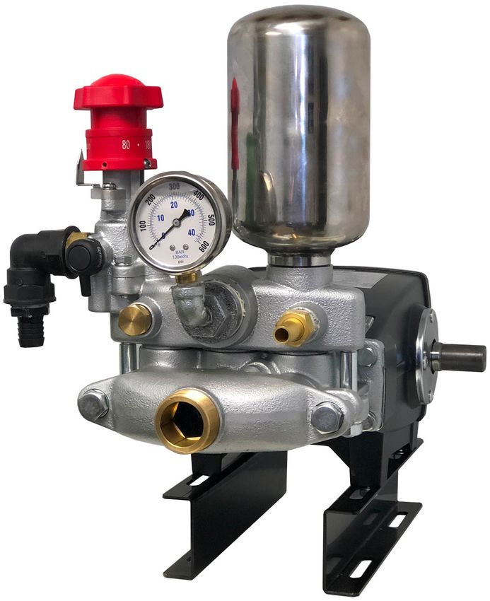
P550 Pump
            Operations and Parts
     Specifications
     Maximum Flow……………………………...…………… 15 GPM
     Maximum Pressure…………………………………..….. 600 PSI
     Maximum RPM…………………………………………. 800 RPM
     Maximum Temperature……………………………………. 140°F
     Inlet Port…………………………………………………………1¼”
     Outlet Port w/1¼ to ¼ Fitting (Gauge/Pressure)...……..…...1¼”
     Outlet Port (Pressure) Qty 2……………………………………½”
     Outlet Port (Regulator Return Line)…...…………...…..……..¾”
     Crankshaft Size…………………………………..……….…24mm
     Dimensions: Standard Mounted:……..……18”H x 13”W x 18”L
     Weight………………………………….………………....…..60lbs.

GNC Industries, Inc., 1401 Pace Rd., Pocahontas, AR 72455
                      1-870-248-9901
                Fax: 870-248-9905 Email: sales@gnci.org
                     Website: www.gncindustries.com

                                                                    1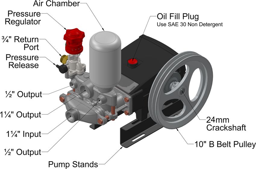
WARRANTY

GNC Industries, Inc., P-Series Pumps are warranted by GNC Indus-
tries, Inc for the period of 1 year from date of purchase or 2 years
from date manufactured (whichever comes first). GNC Industries, Inc.
will repair or replace (at GNC Industries, Inc.’s option) any part or as-
sembly, free of charge, if that part or assembly fails, provided the fail-
ure is due to an unmistakable defect in material or workmanship.
No allowance will be made for consequential damage, labor or ex-
penses incurred as the results of a proven defect. In no event will
GNC Industries, Inc. be liable for any loss of profits or other conse-
quential damages, even if GNC Industries, Inc. has been advised of
the possibility of such damages.
GNC Industries, Inc. assumes no responsibility for accidents or inju-
ries resulting from maintenance or adjustment of product while prod-
uct is in operation.
Since GNC Industries, Inc. has no control over the operational tech-
niques or chemicals used, GNC Industries, Inc. assumes no liability
for the consequences of the use or misuse of any equipment by the
purchaser, their employees or others.
Maximum operation speed and pressure is specified in individual and
applicable instructions.
GNC Industries, Inc. reserves the right to improve any product with-
out being obligated to provide that change on equipment sold and/or
shipped prior to the product change.
Modification of equipment voids all warranties written or implied.
Warning:
1. Never point the spray gun at people or animals.
2. The pump will produce high temperatures when operating.
3. Keep hands and clothing clear of the belts and pulleys when operating the
pump.
Before Use/Start Up:
1. Check every fastener, including all hose clamps, to make sure that the spray-
er and the engine are installed firmly to the frame.
2. Align the pump and engine pulleys in a straight line and tighten the belts ap-
propriately.
3. Check engine (see engine manual) and pump oil (non-detergent). Fill as
needed to recommended levels. DO NOT OVER FILL!
4. Check engine fuel. Fill as needed, with engine manufacture recommended
fuel.
5. Attached the spray gun to the spray hose and tighten all clamps.
6. Set the pump pressure regulator to “Pressure Release” and make sure the
pressure regulator knob is set to “Start”.
7. Check the on/off switches of engine.
8. Start engine.
9. Set the pump pressure regulator to “Spraying”.
10.Adjust the pressure by turning the adjustable pressure regulator valve clock-
wise.
During Use:
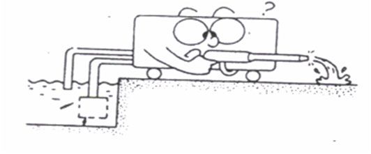
1. Make sure the pump has sufficient liquid supply to allow the pump to reach
its working pressure.
2. To prolong the life of the pump, always operate the machine within its speci-
fied pressure limits. Adjust the pressure by turning the adjustable regulator
knob clockwise.
3. In order to avoid any damage to the packing and the pump, shut off the en-
gine or motor when temporarily stopping the unit for more than 5 minutes.
4. Avoid running the pump without liquid.
3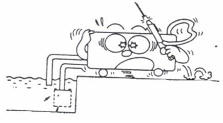
After Each Use:
1. Set the pressure regulator switch to “Pressure Release”, and run the pump
with clean water to prolong the life of the pump.
2. Set the pressure regulating knob to “START” when the pump is not in use.
Maintenance:
1. Change the oil in the pump after the first 10-15 hours of use. After this,
change the oil in the pump after every 70 hours of use. NOTE: Always make
sure the oil is clean and visible thru the oil sight gauge Ref#11A before
operating.
2. Change or replace components, based on the symptoms as listed in the
trouble shooting section.
How to Change Oil:
1. Remove Ref # 12A Drain Plug. Allow the oil and any sludge to drain from
the crankcase into an EPA approved collection device.
2. Replace Ref # 12A Drain Plug once the crankcase has been drained.
3. Remove Ref # 7A Oil Fill Cap and fill crankcase with NON Detergent oil (see
chart) until the oil level reaches the center mark in Ref # 11A Oil Window.
4. Once filled, replaced Ref # 7A Oil Fill Cap.
Specifications Pump Oil
Maximum Flow……………………………...…………… 15 GPM Non-Detergent
Maximum Pressure…………………………………..….. 600 PSI
SAE30 Weight
Maximum RPM…………………………………………. 800 RPM Engine Oil
Maximum Temperature……………………………………. 140°F Recommendations
Inlet Port…………………………………………………………1¼”
Outlet Port w/1¼ to ¼ fitting (Guage/Pressure)...…………..1¼”
Outlet Port (QTY 2)………………………….…………………..½”
Outlet Port (Regulator Return Line)………………...…..……..¾”
Crankshaft Size…………………………………..……….…24mm
Dimensions: Standard Mounted:…..…..……..18”H x 13”W x 18”L
Weight……………………………….….…...……………......60lbs.
NOTE: Not following proper procedures as listed in the detailed product manual may void
all warranties
Page 3
P550
                                                                                                  Part# 43-550-00

Ref#    Item #     Description                           Ref#    Item #  Description
 1A    42-550-01   Crankcase, Set Pins, & Plate          29A  42-530-29 Bolt & Washer
  2    42-550-02   Piston Oil Seal                       31A   42-550-31 Pulley with Bolt Set
  3    42-550-03   Dust Cover                             41   42-550-41 Bolt & Washer
  5    42-530-05   Screw For Crankshaft Oil Seal Cover   42A   42-550-42 Double End Screw, Nut, & Lock Washer
  6    42-550-06   Oil Seal Cover                        51A   42-550-51 Suction Chamber Assembly
 7A    42-550-07   Oil Inlet Cover                       53A   42-550-53 Bolt & Washer
  8    42-550-08   Gasket for Rear Crankcase Cover       60A   42-530-60 Connecting Hose with O-Ring
  9    42-550-09   Rear Cover                             65   42-550-65 Outlet Chamber
 10    42-530-10   Screw for Crankshaft Rear Cover        70    FT-F12B  ½” Brass Plug
11A    42-530-11   Oil Window Assembly                   75A   42-550-75 Air Chamber Surge Tank with O-Ring
12A    42-530-12   Oil Drainage Plug Assembly             76 FT-GAL-SE14 ¼” Street Elbow
 13    42-530-13   Crankshaft Key                         77  FT-TW12B ½” MNPT x ½” HB Swivel
 14    42-550-14   Crankshaft                             78   FT-3LL34 ¾”x¾” FNPT Fitting
15A    42-550-15   Connecting Rod Assembly                79    FT-3A34  ¾” MNPT x ¾” HB Poly Fitting
 16    42-550-16   Crankshaft Bearing                    200 43-530-200 Pressure Regulator Assembly
 17    42-550-17   Crankshaft Oil Seal                   535 43-550-535 Cylinder Head w/ Preinstalled Packing
 18    42-530-18   Crankshaft Cover                      550 43-550-550 Replacement Valve Kit (6pcs)
19A    42-550-19   Piston Assembly                        NA  43-550-580 Rebuild Kit (Ref #s 550 & 525)
 26    42-550-26   Piston Pin                             NA  43-550-600 Master Rebuild Kit (Ref #s 550 & 535)
 28    42-550-28   Pump Stands (pair)                    600 42-950-600 0-600psi Pressure Gauge

                                          www.gncindustries.com
Low or Lost Pressure                    No Liquid at Spray Gun               Abnormal Suction

 Ref: 1,2, 3, 4, 5, 6, 10,                Ref: 2, 11, 14, 15, 16             Ref: 2, 3, 6, 7, 8, 11,
 11, 12, 13, 14, 15, 16

                      Abnormal Pump Noise                    Abnormal Vibration

                      Ref: 2, 3, 7, 8, 11, 15,                     Ref: 9

                  TROUBLESHOOTING REFERENCE
1.  Spray gun tip too large or worn
2.  Suction filter clogged
3.  Loose suction line connection
4.  Malfunctioning pressure gauge
5.  Malfunctioning pressure regulator
6.  Worn pump suction and discharge valves
7.  Over speeding the pump
8.  Suction line too small
9.  Pulsation dampening chamber full of water
10. Worn pump valve chamber
11. Foreign object in suction line
12. Plunger packing worn
13. Pump drive belts loose
14. Pressure regulator by-pass valve open
15. Suction line valve closed
16. Drive pulley spinning on pump or engine shaft. Replace drive key.

                             www.gncindustries.com
Quick Reference
Initial Inspection
Check pump and engine oil levels
Check engine gas level. Add fuel as needed
Fill Tank—DO NOT RUN UNIT DRY
Operations
Set engine switch to “ON”
Set engine gas shut-off to “OPEN” position
Set engine choke to “OPEN”
Set engine throttle to “FULL” (Rabbit)
Set pump regulator red knob to “START”
Set pump regulator black knob to “PRESSURE RELEASE”
Pull engine recoil cord to start engine
Set engine choke to “CLOSE”
Set regulator valve - To “SPRAY”
Adjust regulator knob to desired PSI
Read complete manual for full details.
www.gncindustries.com
7

You can also read