OSCAR-III Installation Manual, WA - January 2021 Lowridge Onsite Technologies, LLC
←
→
Page content transcription
If your browser does not render page correctly, please read the page content below
OSCAR-III Installation Manual, WA
          January 2021

           Manufactured by:

 Lowridge Onsite Technologies, LLC
              PO Box 1179
        Lake Stevens, WA 98258
             877-476-8823

        info@lowridgetech.com

      www.lowridgetech.com

                                     1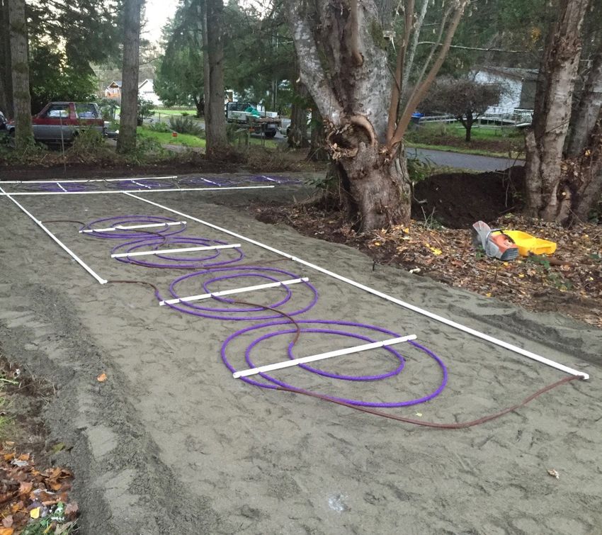
Table of Contents
System Overview
Prior to Installing an OSCAR-III unit
List of Components
Loading and Unloading Instructions
Installation Steps:
    1. Determine the orientation and position of the tanks.
    2. Excavate the holes for tanks.
    3. Setting tanks.
    4. Plumbing
    5. Install dosing pump and headworks.
    6. Plumbing connections
    7. Wire control panel, floats, and pump (power requirements).
    8. Pump and float settings
    9. Back fill and water test.
    10. OSCAR-III installation
    11. Panel Operation and Start-up procedures.

Replacement Instructions:
   1. Solenoid valves
   2. Coils
   3. Dose/Flush pump
   4. Discharge pump

Material Specifications:
   1. Media
   2. Treatment Vessels
   3. Plumbing
   4. Assembled Components
           a. Headworks
           b. Coil
   5. Pump

                                                                    2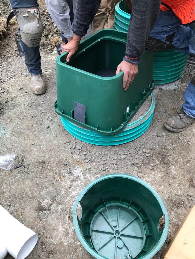
Refer to Website for OSCAR Layout Detail

    1500

3
System Description:

       The OSCAR-III treatment unit is comprised of 1,500 gallon treatment vessel, 1,000
gallon pump/surge tank, headworks, coils, C-33 sand, and control equipment.

        Wastewater is collected in an approved treatment vessel where CBOD5 and TSS levels
are reduced to at least 100 and 75 mg/l, respectively. Effluent flows from the treatment
vessel to the pump/surge tank. Effluent from the pump/surge tank is dosed through a 120
mesh disc filter to the OSCAR-III coils installed in ASTM C-33 sand. Effluent discharged from
the coils is treated by the ASTM C-33 sand prior to infiltrating into the receiving soil and final
discharge.

       Prior to Installing an OSCAR-III Unit:
        Before installing a OSCAR-III unit, the installer must complete in-class and in- field
training by representatives designated by Lowridge Onsite Technologies, LLC. The Installer
must insure that no water softener discharge is plumbed into any of the drains that feed the
system. The residential OSCAR-III unit is intended to treat only wastewater generated by
normal activities from laundry machines, toilets, showers, and kitchen and bathroom sinks.
No special chemical additives are needed for the normal functioning of the OSCAR-III unit.

List of components:
   1. Control panel: LF1P-RF-BLWRR

   2. Reverse flush Headworks: three (3) oil filter 0-100 psi pressure gauges, one (1) 3/4”-
      120 mesh, 130 micron Arkal™ disc filter, five (5) Netafim 1” normally closed solenoid
      valves and container.

   3. Float switches (2)

   4. Discharge pump, ½ hp

   5. 3/4” ARAD flow meter

   6. OSCAR-III coils

   7. Misc. fittings and blank tubing

Unloading and un-packaging instructions:
                                                                                                     4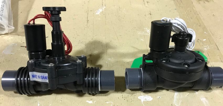
Lowridge Onsite Technologies, LLC takes great care to manufacture and package the OSCAR-
III unit to prevent damage during shipping and handling. It is expected that everyone from the
manufacturing personnel to the installation crew take reasonable steps not to drop, throw, or
damage the product. Do not handle the Coil by the tubing.

If there are defects in any of the components, call Lowridge.

Installation steps:
For reference, please see instructional videos on our website at: www.lowridgetech.com,
click on “Training Video” page, select Washington State and then OSCAR-III.

Step 1: Determine the orientation and position of the
tanks.
Some designs will have specific locations for the system components based on required set -
backs, elevation, logistical issues, or aesthetic concerns. Before excavating begins, verify that
the proposed locations of the tanks are laid out in a manner that will allow for efficient pipe
connections.

Step 2: Excavate the holes for tanks.
Excavate the tank holes as per the tank manufacturer’s recommendations. Take appropriate
steps to insure the tanks will not settle after backfill.

Step 3: Setting tanks.
Tanks: Set tanks according to tank manufacturer’s recommendations.

Step 4: Install dosing pump.
Place the pump into the pump/surge tank. Attach a 1” union on the horizontal supply line and
exit the tank through the riser wall. Make sure to use an appropriate grommet or other
method to insure the protrusion is water tight.

Step 5: Install headworks and flow meter.
The best installation location of the headworks is on top of one of the tanks. The tank top
provides a solid base of support and acts as a barrier against mole and gopher infestation. If
the risers are taller than 12”, cut an additional riser for an extension. Cut the rise pipe the
difference between the hight of the tank risers and the hight of the reverse flush headworks
(12”). Place the extra riser piece on the tank where the headworks is located. Fill the riser
with compacted soil or other aggregates. Place the headworks on the riser and secure the

                                                                                                  5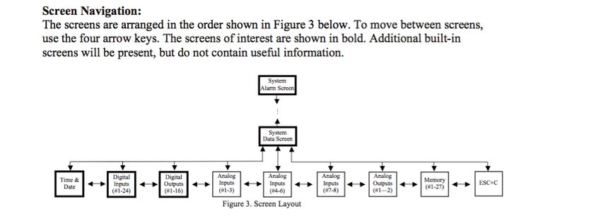
headworks to the riser with screws. Plumb the pump, meter and headworks at right angles as
shown below.

Step 6: Plumbing connections
The headworks has four or five plumbing connections: pump line from dosing pump, OSCAR-III
supply line, OSCAR-III flush line, flush vent line to tank inlet. Plumb the connections to the
headworks so that the pipes are supported by the top of the tank or hand bed the pipes
before backfilling the system.

Step 7: Wire control panel, floats, and pump.
Mount the control panel on a post chest to eye level, not on the side of the house.

Always use PVC electrical conduit between the splice boxes and the control panel and follow
all applicable electrical codes. Do not use direct burial wire on OSCAR-III systems. Follow the
wiring directions provided inside the control panel.

Power requirements for the OSCAR-III system are as follows:
   •   Discharge pump, 110 volt, up to 18 amps start and 11 amps running
   •   Headworks 24 volts, 0.4 to 0.6 amps

Step 8: Floats and Pump settings.

                                                                                                  6
Set float using the floats and float clips provided. The bottom float (Timer enable float)
should be set at a minimum of 24” above the bottom of the tank to insure the entire pump
motor and wet end are completely submerged. The top float (high level alarm) should be set
at least 6” above the bottom float. A greater distance can be used if a large working volume
is required.
Step 9: Back fill and water test.
Prior to backfilling, all tanks should be water tested and all start-up procedures must be
completed. Fill tanks to 2” above riser connections and mark water level. There should be no
measurable water loss for 2 hours. Backfill tanks with appropriate material. At all times
follow tank manufacturer’s instructions. Hand-bed all pipes.
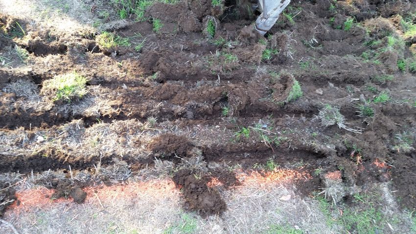
Step 10: OSCAR-III installation.
Installation:
Before preparing the basal area for the sand layer the soil moisture content must be
checked to prevent smearing the soil interface. Dig a small excavation in the basal area with
a hand shovel. The excavation need only be 12” wide and 12” deep. If the exposed sides of
the excavation are shiny without any cracks or crumbled edges, the soil is too moist. If the
exposed soil surface crumbles and cracks, the soil is dry enough for preparation.
To prepare the soil interface, stake the basal area and remove any forest duff and
forest under-growth, if present. Trees and stumps should be left in place. In pasture or lawn
areas, mow the grass as short as possible. After removing as much loose organic material as
possible, prepare the soil surface 2-3” deep parallel to the contour throughout staked basal
area. The teeth of a backhoe bucket can be used. Do not intentionally remove sod.
Apply the base layer of sand media as per the design. The top of sand layer under the
coil must be level.
7Place the coils and connect the supply and flush manifolds as prescribed in the design.
Place the final 6” of sand media for final cover. It is recommended to immediately
broadcast grass seed or plant a ground cover, preferably periwinkle (vinca-minor). A layer of
natural mineral soil can be added to cover the sand. Do not use a manufactured top soil mix.
Also, avoid soil that is high in organic matter. A couple of inches of beauty bark could be used
to top dress the sand.
8Step 11: Panel Operation and Start-up procedures.
Panel Operation:
The LF1P-RF-BLWRR control panel is a 110 volt universal panel for most single family
OSCAR-III systems. It has the capacity to operate two major outputs: a discharge
pump and the “Reverse Flush” headworks. Also, the panel is capable of operating a
pressure switch to monitor blower failure. All logic is controlled by a Siemens Logo.
The pump operation options are as follows:
• Discharge Pump (Pump #1): is operated in a time-dose mode. Pump #1
pressurizes the OSCAR-III and back-flushes the disc filter and forward flushes
the OSCAR-III Coils.
The timer has the following factory default settings:
• Discharge pump dosing: 7 minutes 38 seconds off, 22 seconds on. (V1_OFF,
V1_ON)
• Disc filter flush: after pre-set number of dose cycles have completed (90
doses), the disc filter flush “ON” cycle runs for 15 seconds. (V2_ON).
• Coil flush: after Disc filter flush is completed, the Coil flushes for 2 minutes
(V1V3_ON).
Start Up Procedures:
Prior to conducting any of the following procedures, inspect the wiring to
ensure the system is correctly wired. Pull the float tree from the tank and place
across the tank opening so all the floats hang down. Now power up the system and
turn all the breakers to the “ON” position and all of the toggle switches in the off
position. Ensure there is enough water in tanks to conduct pump tests.
a. Test floats:
On the Seimens Logo scroll to the input screen as shown here:
9Find this screen
The actual screen will look like this:
When lifting the floats check this screen to determine if the floats are wired into the
correct position. When the floats are lifted a corresponding digit will be back lit. The
input values are as follows:
1 = bottom float
2 = top float
Test floats:
Lift top float. Input indicator “2” will back light and the alarm should sound
and the beacon should illuminate.
Lift bottom float. Input indicator “1” will back light.
10Place floats back into tank.
b. Test pumps and valves:
Discharge pump and valves:
Place valve 1 & 2 toggle switch and pump 1 toggle switch to MAN position.
Pump should dose and all three pressure gauges should stabilize about 50 psi.
Gauge 3 may read as low as 40 psi. No water should be flowing into septic tank.
Place valve 3 & 4 toggle switch to MAN and valves 1 & 2 toggle switch to OFF,
pump #1 in MAN. Pump should run, pressures should change: gauge 2 highest
pressure, gauge 1 less than 2, and gauge 3 should indicate 0 psi. Water should
be flowing into septic tank very rapidly.
Place valves 1 & 2 and valve 5 in MAN position and valves 3 & 4 in OFF position,
and pump 1 in MAN. Pressure on gauge 1 & 2 should indicate about the same
pressure, and gauge three should indicate between 0-3 psi and water should be
flowing into septic tank at a moderate rate.
Position all toggle switches to AUTO.
c. Check timer default settings:
V1 OFF = 7minutes 38 seconds
V1 ON = 22 seconds
V2 OFF = 30 seconds
V2 ON = 15 seconds
V1V3 OFF = 30 seconds
V1V3 On = 2 minutes
11Replacement Instructions:
There are several components that are critical to process performance: solenoid
valves in the headworks, drip tubing in the Coil, and the discharge pump.
Solenoid Valves, 2-way throttling valve, Netafim part number, LVET1GH2:
To replace remove six screws, remove bonnet, remove and replace bonnet and tighten
screws. Valves can be purchased from Lowridge Onsite Technologies.
LVET1GH2
Coil, Netafim Bioline, 08WRAM.4-06V500:
To replace the Coil remove sand media from top of Coil, cut the 1/2” poly feed lines
adjacent to the manifolds, fold the feed lines up, and remove Coil. Place the new Coil in the
sand, fold down the feed lines and couple to the feed lines, and cover Coil with sand. Coils
can be obtained from any OSCAR-III dealer or Lowridge Onsite Technologies, LLC.
12Discharge pump, Lowridge Onsite Technologies, 1/2 hp, 30 gpm Lot-30:
Cut power to pump, disconnect wire connections in splice box, remove pump from
tank, and disconnect pump from piping. Connect new pump piping, connect wiring in splice
box, place pump into tank, and re-energize power to pump circuit.
Material Specifications:
Media:
OSCAR-III
ASTM C-33 concrete sand as per WADOH Recommended Standard & Guidance for
Intermittent Sand Filter.
Treatment Vessels: All treatment vessels must on the WA DOH approved List of Registered
Sewage Tanks. Man-hole openings must be 24” or greater nominal size to surface grade with a
locking lid to preclude un-authorized access. All tanks must be water tight to the riser lid
opening. All protrusion through the riser wall for electrical conduits and other piping must be
sealed to preclude any water infiltration. Containment vessels can be concrete, polyethylene,
or fiberglass.
Concrete: Where ever possible, concrete tank bodies should be single piece
construction. Man-hole risers should be cast in-place.
Plumbing: All piping must be PVC. The 1” supply and flush lines must be sch40.
Assembled components: Lowridge assembles the following components: headworks, Coil
(partially assembled), and Coil manifold connections.
Headworks: the headworks for the OSCAR-III is made of all 1” sch 40 PVC pipe and
fittings, 1” NC Dorot solenoid valves, 3/4” Arkal disc filter (120 mesh, 130 micron), Three oil
filled pressure gauges, and a polyethylene valve box with lid.
Coil: The Coil is constructed of Netafim Bioline™ (0.42 gph emitter at 6” spacing)
attached to a 1/2” or 1” PVC bracket.
Discharge Pump: The discharge pump is an Lowridge Onsite Technologies, 1/2 hp, 30 gpm,
model LOT-30.
13You can also read