Numerical study on airflow performance and mechanical characteristics of centrifugal fan
←
→
Page content transcription
If your browser does not render page correctly, please read the page content below
E3S Web of Conferences 356, 04016 (2022) https://doi.org/10.1051/e3sconf/202235604016
ROOMVENT 2022
Numerical study on airflow performance and mechanical
characteristics of centrifugal fan
Minkai Bai1, Haihui Tan2, and Zhan Liu1*
1Schoolof Mechanic and Civil Engineering, China University of Mining and Technology, Xuzhou, China
2Schoolof Mechanical and Electrical Engineering, University of Electronic Science and Technology of China, Zhongshan Institute,
Zhongshan, China
Abstract. As small fans are widely used to dissipate the heat of the electronic components, a series of
special requirements are put forward on the airflow performance and stress characteristics. In the present
study, the computational fluid dynamics (CFD) method is adopted to study the airflow characteristics of a
specific type of fan, including the fluid pressure distribution, flow velocity field and fluid streamline
distribution. The stress characteristics of the fan blades are systematically analyzed based on the fluid-solid
coupling and thermal-solid coupling methods. The results show that with the rotation speed of 1400 rpm,
the airflow velocity in the air duct is unevenly distributed, and some eddy disturbances form and occur in
the flow field. To improve the operating efficiency of the fan, appropriate optimization schemes should be
adopted to reduce the intensity and range of the eddy influence. When the inlet temperature is 20 °C, the
stress on the impeller is mainly caused by centrifugal force and thermal load. As the inlet temperature
increases, the effect of the thermal load becomes increasing. While for the centrifugal force, its influence on
the impeller gradually disappears and completely disappears when the temperature reaches 50 °C.
1 Introduction deformation on the impeller with the three-dimensional
finite element method. However, with increasing of the
Fans are widely used in industrial and civil engineering as heat dissipation requirement, the effect of temperature on
ventilation and dust removal equipment[1]. With the the impeller stress becomes increasingly evident.
development of electrical equipment, fans are utilized to Zheng[11] used a solid-fluid coupled method to analyze
enhance heat dissipation[2] generated by computers and the effects of temperature and pressure on the stresses of
refrigerators. Different application scenarios put a series the impeller with different inlet conditions.
of requirements on the flow field and operation In this study, a three-dimensional numerical
performance of fans[3, 4]. Until now, more investigations simulation is conducted on a specific model of the fan.
were conducted on the performance of fans in different The velocity and pressure fields are simulated, and the
cooling scenarios. Yamam et al.[5] analyzed the flow patterns within the fan are analyzed. As the impeller
performance of fans in electronic cooling by numerical material of the fan studied in this paper is plastic, which
simulations and evaluated the accuracy of the numerical is influenced by temperature in some heat dissipation
simulations. Guo et al.[6] numerically researched the flow scenarios, the force characteristics and deformation of the
field of a high-voltage fan on fuel cell vehicles and fan impeller at different temperatures are considered and
obtained the optimal layout strategy of the dual fan system. researched. The fluid-solid coupling and thermal-solid
The flow field inside the casing is a complex three- coupling methods are adopted to simulate the force
dimensional strong cyclonic flow with highly nonlinear characteristic of the fan impeller. With the deformation
characteristics. During the high-speed rotation of the fan, and stress distribution of the fan impeller obtained, the
the impeller is subjected to centrifugal force, the reliability of the fan is evaluated. The present study is
aerodynamic force caused by the flowing air and the significant to the optimal design of the fan.
thermal load in some heat dissipation scenarios[7]. When
fans are constantly operated at high rpm, both the noise
generated by the fan and the impact on the impeller 2 Numerical simulation
become obvious and serious[8]. As the requirements for
the various parameters of the fan become increasingly 2.1 Physical model
high, the stress study on fan impellers has become of great
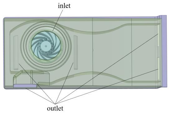
interest. Glessner[9] adopted analytical techniques to The centrifugal fan, as shown in Fig. 1, mainly consists of
predict the determination of stresses in the fan impeller. the impeller, hub and shell. The rotation speed of the fan
Zhu[10] researched the stress distribution and is 1400 r/min.
* Corresponding author: liuzhanzkd@cumt.edu.cn
© The Authors, published by EDP Sciences. This is an open access article distributed under the terms of the Creative Commons Attribution License 4.0
(http://creativecommons.org/licenses/by/4.0/).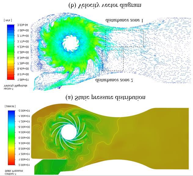
E3S Web of Conferences 356, 04016 (2022) https://doi.org/10.1051/e3sconf/202235604016
ROOMVENT 2022
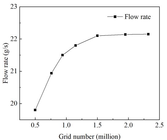
mesh quality[13]. The numerical model can be divided
into non-rotating and rotating regions according to
different motion characteristics. The rotation area is
divided into dense grids and the non-rotating region with
sparse grids. To verify the accuracy of the mesh, the mesh
independence analysis is conducted. As Fig. 2 shows,
when the grid number exceeds 1.5 million, the flow rate
at the fan inlet has small variations. Therefore, the final
grid number of the model is determined to be 1.55 million.
3 Results and discussion
Fig.1. Physical model of fan
3.1 Flow field analysis
2.2 Model calculation methods and boundary
conditions Driven by the rotating impeller, air firstly enters the fan
along the axial direction of the impeller, then flows
In this paper, the commercial Fluent software is used to toward different outlets. During this process, the air
simulate the fluid flow within the fan. The Multiple obtains certain momentum under the continuing
Reference Frame (MRF) model is utilized to calculate the compression by the rotating impeller. The static pressure
coupling relationship between the rotation domains and and velocity vector distribution for the middle section of
the adjacent flow domains in steady-state. The rotational the fan are shown in Fig. 3. As Fig. 3(a) shows, the
coordinate system is adopted in the rotating region, while pressure at the inlet of the impeller is very low, and the
the entrance and exit regions are relatively static. The inlet external environment air can be inhaled. At the outlet of
and outlet of airflow are set as pressure ports, and the the impeller, the air has a high velocity and a low pressure.
initial gauge pressure is set to 0 Pa. That is to say, there Once thrown from the impeller, the air velocity decreases
was no additional pressure effect. The fan blade is defined and the pressure increases gradually. Some fluid-flow
as a rotating wall, the shell part is set with stationary phenomena within turbomachinery, such as typical
boundary conditions, and the standard wall function is set unsteady and rotating flow phenomena, are shown
in the near-wall region. The Static Structure and Steady- schematically in Fig. 3(b). It can be seen that in the throat
State Thermal are used to carry out fluid-structure and of the runner, the velocity-pressure distribution of the
thermal-solid coupling of the model to analyze the stress airflow is more chaotic, and there are two regions with
and deformation of the impeller. Ye[12] verified the great disturbances. Disturbance zone 1 takes shape
feasibility of this model by comparing the simulation between two faster flow regions, which is disturbed due
results with the experimental results. This paper simulates to the velocity difference between higher and lower
the k-ω model and k-ε model separately and finds that velocity fluids. An anticlockwise vortex forms in
they have similar simulation results, but k-ω has better disturbance zone 2. The vortex is caused by the split effect
convergence. Finally, the SST k-ω turbulence model is of the side outlet, with a low flow rate and high pressure.
used for the steady-state simulation of the fan model. Static
Pressure
20
16
12
2.3 Mesh generation 8
4
0
-4
-8
-12
-16
-20
[pascal]
(a) Static pressure distribution
Velocity
Magnitude
10.60 Disturbance zone 2
9.51
8.45
7.39
6.34
5.28
4.23
3.17
2.11
1.06
3.03e-4
[m/s] Disturbance zone 1
(b) Velocity vector diagram
Fig. 2. Grid independence verification Fig. 3. Static pressure distribution and velocity vector diagram
Based on the complex geometric structure, the calculation These phenomena produce fluid rotation, which
mesh is generated by using a polyhedral type element and appears as secondary, smaller scale, dissipative fluid
the methods of local encryption are used to improve the motions, which may severely distort the flow field and
2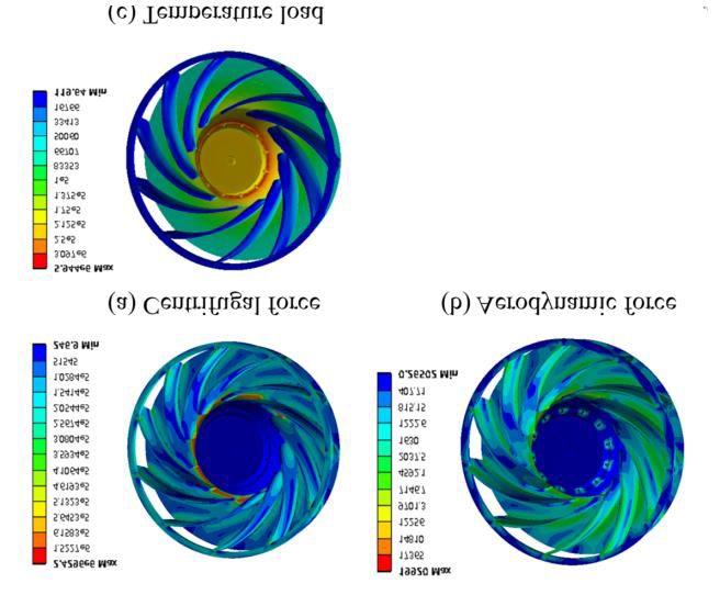
E3S Web of Conferences 356, 04016 (2022) https://doi.org/10.1051/e3sconf/202235604016
ROOMVENT 2022
cause significant power losses in fans. Therefore, it is stress distribution on the blade is mainly influenced by the
necessary to reduce the disturbances in practical cases. centrifugal force. The stress caused by centrifugal force,
The shape of the duct and the position of the outlet cause aerodynamic force, and thermal load are 1.039×10⁵ Pa,
obvious influences on the fluid flow. Adjusting the runner 1.027×10³ Pa, and 1.96×10⁵ Pa, respectively. It can be
is the main direction of optimizing the model. For this found that the stress on the impeller is mainly caused by
model, the throat cross-sectional area can be reduced to centrifugal force and thermal load and is less influenced
merge the two high-velocity regions to reduce the velocity by aerodynamic force. Thermal stress accounts for >50%
difference. The position of the outlet side runner can be of the total stress when the inlet temperature is 20 °C,
also adjusted to reduce the disturbance caused by the split which means that the temperature must be considered for
flow to avoid the creation of the vortex. analyzing the stress of the impeller.
The maximum stress on the impeller is 4.03 MPa,
while the impeller’s yield stress is 58.2 MPa. Hence the
3.2 Stress analysis of fan impeller
strength of the impeller meets the requirement. Combined
The impeller is made of PBT. The material properties of Fig. 5 (a) and Fig. 4 (a), it is clear to see that the stress
the impeller are shown in Table 1. distribution on the blade under total load is similar to that
of the blade under the centrifugal force, which further
Table 1 The main characteristic parameters of the impeller indicates that the stress distribution on the blade is mainly
Parameter Elastic Modulus Poisson's ratio influenced by centrifugal force. The total displacement
Value 1930 N/mm2 0.398 distribution of the impeller in cylindrical coordination is
shown in Fig. 5. The maximum deformation of the
The working revolution is set as 1400 r/min and the impeller occurs on the tip of the blade, with a value of
rotation direction is clockwise around the impeller axis. 2.13×10⁻⁵ m. While the minimum deformation occurs on
The inlet temperature is set as 20 °C and the influence of the hub and the average deformation is 1.14×10 -5m. It is
the gravity is neglected. It can be seen from Fig. 4(a) and worth noting that the deformations caused by centrifugal
(b) that the equivalent stresses of the impeller under force and thermal load are 1.21×10⁻⁵ m and 1.52×10⁻⁵ m,
centrifugal force and aerodynamic force have the same which are larger than the deformation under the total load.
trend. The maximum stress occurs on the contacted The results show that the centrifugal force and the thermal
position of the blade and the hub, and the minimum stress load act on the impeller in different bending moment
occurs on the hub. As Fig. 4(c) shows, under the thermal directions, even in the opposite direction. Therefore, with
load, the equivalent force is concentrated on the hub. the increase of load, the deformation of the impeller is not
Moreover, the centrifugal force and aerodynamic force simply superimposed, but also decreases due to the
have similar effects on the stress distribution on the blade. mutual restraint of load.
4.03e6 Max 2.13e-5 Max
The blade has large stress around the contact position with 2.89e6
1.75e6
1.94e-5
1.74e-5
6.16e5
the disc and the stiffening ring. The stress at the center of 5.61e5
1.55e-5
1.36e-5
5.04e5
the blade is relatively small. For the blade stress 4.48e5
3.92e5
1.16e-5
9.69e-6
7.75e-6
distribution caused by the thermal load, large stress occurs 3.37e5
2.81e5 5.82e-6
2.25e5 3.88e-6
on the contact position with the disc and the stress 1.69e5 1.94e-6
0 Min
1.13e5
decreases with the increase of the distance from the 57652
1833.8 Min
contact surface.
2.43e6 Max 19920 Max
1.52e6 17365 (a) Stress distribution (b) Deformation distribution
6.16e6 14810
5.64e5 12256
5.13e5 9701
7146
Fig. 5. Stress distribution and deformation of the impeller
4.62e5
4.11e5 4592 under total load
3.59e5 2037
3.08e5 1630
2.57e5
2.05e5
1222
815
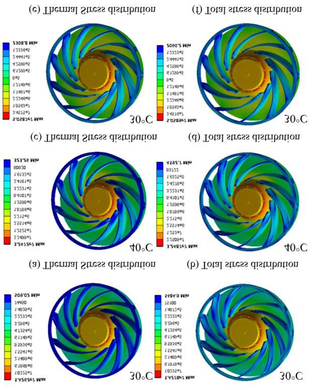
It can be seen from Fig. 6 (a), (c) and (e) that with the
1.54e5
1.03e5
408
0.26 Min inlet temperature of 30 °C, the thermal stress on the blade
51545
246.9 Min is concentrated at the bottom of the blade. The influence
(a) Centrifugal force (b) Aerodynamic force range of the thermal load expands with the increase of the
5.94e6 Max
inlet temperature. When the inlet temperature reaches
3.10e6
2.50e5 50 °C, it eventually covers almost the entire blade. As
2.13e5
1.75e5
1.37e5
shown in Fig 6 (b), (d) and (f), when the inlet temperature
1.01e5
8.33e4 is 30 °C, the stress on the impeller is mainly caused by the
6.67e4
5.01e4 thermal load. Meanwhile, the action characteristic of
3.34e4
1.67e4
119.6 Min
centrifugal force (larger stresses around the contact points
with the hub and stiffening ring) is also imposed on the
blade. However, as the temperature increases, the
(c) Thermal load
centrifugal force characteristic gradually disappears and
Fig. 4. Stress distribution of the impeller under different loads almost completely disappears when the inlet temperature
reaches 50 °C. Correspondingly, the thermal load
By comparing Fig. 4 (a) and (c), it can be seen that the
gradually tends to play the dominant role. As Fig. 7 shows,
stress caused by centrifugal force mainly appears in the
with the increase of the temperature, the magnitude of the
blade and the thermal stress mainly occurs on the hub.
thermal stress is close to the magnitude of the total stress.
Therefore, at the operating temperature of 20 °C, the
3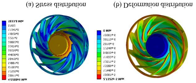
E3S Web of Conferences 356, 04016 (2022) https://doi.org/10.1051/e3sconf/202235604016
ROOMVENT 2022
When the inlet temperature is 50 °C, the two magnitudes the increase of the load, the deformation of the impeller is
are almost identical. This means that the effect of other not only simply superimposed but also decreased due to
loads on the impeller can be neglected. It is worth the mutual restraint of the loads.
mentioning that when the inlet temperature is 50 °C, the (3) With the increase in temperature, the thermal load
maximum stress in the impeller reaches 50.6 MPa, which gradually dominates and the influence of centrifugal force
is quite close to the yield stress. Therefore, to ensure the on the impeller gradually disappears. When the inlet
normal operation of the fan, it is necessary to ensure that temperature reaches 50°C, other loads can be completely
the inlet temperature is below 50 °C. neglected and the maximum stress of the impeller is close
1.46e7 Max
1.02e7 30°C 1.46e7 Max 30°C to the yield limit. To ensure the safety operation
1.02e7
6.19e6
2.15e6
6.19e6
2.15e6
performance, the operating temperature of the fan must be
1.55e6
9.59e5
1.55e6
9.59e5 below 50 °C.
6.17e5 6.17e5
4.73e5 4.73e5
3.29e5 3.29e5
2.22e5 2.22e5
1.48e5
74450
1.48e5
75100 References
509 Min 1484.9 Min
1. W. Choi, M.B. Pate, and J.F. Sweeney, Study of
(a) Thermal stress (b) Total stress bathroom ventilation fan performance trends for
3.25e7 Max 40°C 3.25e7 Max 40°C years 2005 to 2013—Data analysis of loudness and
2.25e7 2.25e7
1.25e7
2.55e6
1.25e7
2.55e6 efficacy. Energy Build., 116: p. 468-477(2016).
2.21e6 2.21e6
1.88e6 1.88e6 2. J. Stafford, E. Walsh, and V. Egan, A study on the
1.36e6 1.36e6
8.41e5 8.41e5
3.22e5
flow field and local heat transfer performance due to
3.22e5
2.42e5
1.61e5
2.42e5
1.61e5
geometric scaling of centrifugal fans. Int J Heat Fluid
80820
323.26 Min
83722
4192.7 Min Flow, 32(6): p. 1160-1172(2011).
3. S.-C. Lin and M.-L. Tsai, An integrated performance
(c) Thermal stress (d) Total stress analysis for a backward-inclined centrifugal fan.
5.06e7 Max
3.46e7
50°C 5.06e7 Max
3.46e7 50°C Comput Fluids, 56: p. 24-38(2012).
1.85e7 1.85e7
2.22e6 2.22e6
1.75e6
4. C.X. Li, S.L. Wang, and Y.K. Jia, The performance
1.75e6
1.27e6
8.01e5
1.27e6
8.01e5
of a centrifugal fan with enlarged impeller. Energy
6.13e5
4.26e5
6.13e5
4.26e5 Convers. Manag., 52(8-9): p. 2902-2910(2011).
2.44e5 2.44e5
1.23e5 1.23e5
2060 Min
5. Y.M. Manaserh, et al., Degradation of Fan
2308.8 Min
Performance in Cooling Electronics: Experimental
Investigation and Evaluating Numerical Techniques.
(e) Thermal stress (f) Total stress Int. J. Heat Mass Transf., 174(2021).
Fig.6. Stress distribution of the impeller at different 6. R. Guo, et al., Research on aerodynamic performance
temperatures and noise reduction of high-voltage fans on fuel cell
vehicles. Appl Acoust, 186(2022).
7. T.R. Jebieshia, S.K. Raman, and H.D. Kim,
Aerodynamic and Structural Characteristics of a
Centrifugal Compressor Impeller. Appl. Sci.,
9(16)(2019).
8. D.V. Bhope and P.M. Padole, Experimental and
theoretical analysis of stresses, noise and flow in
centrifugal fan impeller. Mech Mach Theory, 39(12):
p. 1257-1271(2004).
9. J. Glessner, A method for analyzing stresses in
centrifugal impellers. ASME, (54-A): p. 167(1954).
10. L.D. Zhu, et al., Statics Analysis of Integral Impeller
Based on Finite Element. Adv Mat Res, 753-755: p.
1124-1127(2013).
11. X.Q. Zheng and C. Ding, Effect of temperature and
Fig. 7. Average stress and deformation of the impeller at pressure on stress of impeller in axial-centrifugal
different temperatures combined compressor. Adv. Mech. Eng., 8(6)(2016).
12. X. Ye, et al., Numerical investigation of blade tip
4 Conclusions grooving effect on performance and dynamics of an
axial flow fan. Energy, 82: p. 556-569(2015).
(1) In the fan flow channel, the disturbance or even vortex 13. X. Liu, et al., Experimental and numerical simulation
forms and causes momentum dissipation. The flow investigations of an axial flow fan performance in
channel must be properly adjusted to minimize high-altitude environments. Energy, 234(2021).
interference.
(2) When the inlet temperature is 20 °C, the stress on the
impeller is mainly caused by centrifugal force and thermal
load, and is less influenced by aerodynamic force. With
4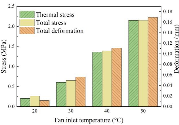
You can also read