Nuclear fusion as a massive, clean, and inexhaustible energy source for the second half of the century: brief history, status, and perspective
←
→
Page content transcription
If your browser does not render page correctly, please read the page content below
PERSPECTIVE

Nuclear fusion as a massive, clean, and inexhaustible
energy source for the second half of the century: brief
history, status, and perspective
         nchez
Joaquin Sa
Laboratorio Nacional de Fusion, CIEMAT, 28040 Madrid, Spain

Keywords                                            Abstract
Fusion, Energy, Plasma
                                                    Fusion energy, based on the use of broadly available inexhaustible resources as
Correspondence                                      lithium and deuterium and with minimal impact to the environment, aims at a
J. S
    anchez, Laboratorio Nacional de Fusion,         change in the energy supply paradigm: instead of its current dependence on
CIEMAT, 28040 Madrid, Spain.                        natural resources and environmental impact, energy would become a technol-
Tel: +34913466159; Fax: +34913466124;               ogy-dependent resource with unlimited adaptive availability and whose unit
E-mail: joaquin.sanchez@ciemat.es
                                                    cost should decrease as technology progresses. This article intends to give a pic-
Funding Information
                                                    ture of where fusion research stands today and the perspectives: the achieve-
No funding information provided.                    ments, the difficulties, the current status, marked by the construction of the
                                                    ITER experiment which will demonstrate the scientific feasibility of fusion
Received: 14 April 2014; Revised: 16 July           power, and the perspectives toward the first demonstration power plant,
2014; Accepted: 17 July 2014                        DEMO, which, according to the European Roadmap, could start the construc-
                                                    tion shortly after the full power experiments in ITER (
Nuclear Fusion                                                                                                                                  J. S
                                                                                                                                                    anchez

reactions in which deuterium will fuse with remaining                         very high temperatures required in the reactor, in the
hydrogen into helium (He3) and later the helium with                          order of several hundred million degrees, are impossible
itself (to generate He4). On Earth, where we cannot count                     to sustain in case any malfunction arises, for example, an
on such strong gravitational forces, we will need to look                     air leak into the reactor would immediately bring down
for more accessible reactions, though still very hard to                      the temperature and extinguish the fusion reaction.
achieve. The fusion reaction with larger cross section                        Another element to be taken into account is that, whereas
under reasonably achievable conditions is the fusion of                       in a fission reactor the amount of fuel inside the reactor
deuterium and tritium, two isotopes of hydrogen. The                          could sustain the reaction for months (and therefore it
reaction produces as a result a helium nucleus and a neu-                     might be more difficult to manage if control is lost), in a
tron and releases 17.6 MeV (mega electron volt) of                            fusion plant the fuel contained inside the reactor would
energy, (91,000 kWh per gram of fuel). Of this energy, 4/                     last for only a few seconds if the supply from outside is
5 is carried by the neutron and the remaining 1/5 by the                      interrupted. As an example: the cooling system, whose
helium nucleus.                                                               failure was the cause of the problems at the Fukushima
   A fusion power plant would be essentially a thermal                        reactor, was not even an important safety component in
plant. The energy released by the fusion reaction is                          the large experiment ITER because there was no signifi-
absorbed by a coolant and extracted to the heat exchang-                      cant residual heat when the operation stops.
ers and to the electricity-producing turbines. The fusion                        The main safety concern in a fusion plant would be the
fuel would be composed of two species: deuterium and                          existence of tritium, which is radioactive and, even if it is
tritium. Deuterium exists in natural water in a fraction of                   not a long-term pollutant (its half life is 12.3 years), it is
33 mg/L. On the other hand, tritium, another, heavier,                        dangerous if inhaled or ingested as tritiated water. Fortu-
hydrogen isotope, is unstable and does not exist in nat-                      nately, tritium is only used as a transition element and
ure. It is usually a secondary product of fission power                       the main supply comes as lithium, but still the storage of
plants. Fusion reactors would generate in situ the tritium                    several kilograms of tritium is difficult to avoid and, as it
they would consume by means of neutron bombardment                            would happen with any other dangerous substance in an
of lithium, another chemical element. Lithium is also very                    industrial facility, safety measures are required to prevent
abundant in nature and, given the fact that the required                      any release to the environment. The current designs
quantities are very small in comparison with the amount                       would guarantee that in the worst case accident, there
of energy obtained, it could be extracted at affordable cost                  would be no need to evacuate people staying outside the
from salts solved in seawater. The estimated reserves of                      facility fence.
lithium in seawater would be sufficient to satisfy the                           The main drawback of fusion as a potential source of
world’s energy needs during many million years and it is                      energy is the difficulty to generate and sustain the reac-
expected that in the future technologies for mastering the                    tion. In order to achieve the reaction, the two colliding
deuterium–deuterium reaction would become available,                          nuclei must get close enough to allow the short range
thus extending the availability of fusion fuel beyond the                     nuclear forces to act, this can only be achieved if their
expected life of the solar system.                                            energy is high enough to overcome the electrostatic repul-
   The main exhaust product resulting from the reaction                       sion of the two positively charged nuclei. Accelerating
is helium, the very same gas we use to fill balloons for                      deuterium or tritium ions to these energies, 15–20 keV, is
children. This element is harmless for people and the                         not particularly difficult, the difficulty arises when we try
environment, it does not contribute to the greenhouse                         to get energy gain from the process: launching an ion
effect and, in fact it does not even accumulate in the                        beam against a target at the required energy would pro-
atmosphere: due to its low weight it escapes to the space.                    duce just a very small fraction of fusion reactions because
In addition, the quantities produced would be very small:                     in most cases the long range coulombian repulsion will
if all the energy in the world would come from fusion,                        deviate the ions, which will miss the target, and also
the amount of helium produced worldwide would be in                           many of them will release their energy in collisions with
the order of several thousand tons a year, to be compared                     the electrons. The only way to achieve an efficient process
with the ten billion ton CO2 per year released currently.                     is to be able to confine the accelerated ions in a closed
   Safety is a major concern on every industrial facility                     space, in such a way that, after having gained the required
and in nuclear plants in particular. One of the advantages                    energy, they have many opportunities to collide before
of a nuclear fusion plant would be its intrinsic safety:                      their energy is lost. The main problem is the availability
fusion plants will be safe not just because they will be                      of a suitable recipient: a gas where the average particle
carefully designed and operated, they will be safe because                    energy is 15 keV has a temperature of 170 million degree.
the physical properties of the process make impossible an                        Since 1950s, scientists have been trying to find this
uncontrolled fusion reaction. As we will discuss later, the                   kind of recipient and have developed two main families

166              ª 2014 CIEMAT, Spanish Ministry of Economy and Competitiveness. Energy Science & Engineering published by the Society of Chemical Industry
                 and John Wiley & Sons Ltd.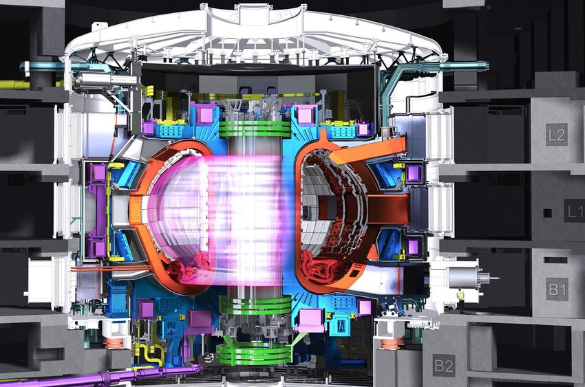
J. S
    anchez                                                                                                                                   Nuclear Fusion

of experiments: inertial confinement, based on a fast heat-                        first developed by I. Tamm and A. Sakharov (who later
ing of the fuel so that it enters the fusion reaction before                       received the Nobel peace prize) in the early 1960’s and
it has time to expand, and magnetic confinement, based                             was rapidly adopted by researchers around the world.
on the fact that at such high temperatures the gas, in state                       Thirty years later (1991), the Joint European Torus (JET)
of “plasma”, is composed of charged particles, which can                           – a tokamak experiment owned by the European Com-
be confined by magnetic fields.                                                    mission and located in Culham, near Oxford (UK) – car-
   Inertial fusion uses an ion beam or a laser, the pre-                           ried out the first D-T experiment toward controlled
ferred option nowadays, as the means of delivering a big                           fusion, providing a substantial amount of energy from
amount of energy in a very short time to the deuterium–                            the fusion reactions [3], few years later (1996–97), JET
tritium (DT) target. The target is illuminated with spheri-                        and the TFTR tokamak (Princeton, NJ) reached fusion
cal symmetry and this produces a pressure wave which                               power levels in the order of 10–15 MW, with a ratio of
converges toward its center. At a given moment, a fusion                           fusion power to heating power of 60% [4, 5].
“spark” should be generated in the center and the heat                                Despite the criticism to fusion researchers to be “always
generated by these initial fusion reactions would propa-                           40 years away” from the goal of fusion power, the reality
gate back the fuel burn toward the rest of the target. The                         is that the efficiency of tokamak experiments, measured
most advanced inertial fusion experiment is currently the                          as the “triple product” of ion temperature, ion density,
National Ignition Facility (NIF) located in the Lawrence                           end energy confinement time (Ti.ni.sE), was growing at
Livermore National Laboratory, (Livermore, CA).                                    comparable pace to that of microprocessors between 1960
Recently, experiments have been reported where the ini-                            and 2000 and will hopefully recover when the large ITER
tial spark of fusion has been found [2]. Its extension to                          experiment will start (see Fig. 1). However, it is necessary
the whole target has not yet been achieved and the energy                          to realize the magnitude of the challenge: the magnetic
production is still a small fraction of that delivered by the                      field confines very well a single particle, but, as the many
lasers, however it is a promising result. A similar experi-                        particles collide, there is diffusion across field lines and
ment, the “Laser Megajoule” is under construction in                              both particle and energy flow slowly away. In order to
France, essentially with military purposes: inertial fusion                        minimize these losses we have two essential tools: one is
experiments can be used to validate the models which are                           to increase the magnetic field, but this has a limit for the
the basis for the computer simulation of thermonuclear                             superconductor coils which generate it, so it is difficult to
explosions.                                                                        envisage a device with an average field above 6–7 Tesla;
   In parallel, the largest worldwide effort toward fusion                         the second tool is to increase the machine size. “Wind
energy has been and is being devoted to the so called                              tunnel” comparisons with tokamaks of similar geometry
“magnetic confinement”. The DT fuel at such high ener-                             and increasing size have shown that in order to achieve
gies is on “plasma” state, a gas where ions and electrons                          “ignition” conditions, a situation where the energy gener-
move separately, and can, therefore, be confined by a                              ated in the fusion reactor can compensate the losses and
magnetic field, which essentially allows particles to move                         maintain the required high temperatures which sustain
freely along the field lines but forces them to move in                            the reaction, we need a hot plasma volume in the order
small circles when trying to go in perpendicular direction.                        of 1000 m3 for a standard magnetic field value of 5–6 T.
The next step is to construct a configuration where field                          This means very large, complex, and expensive devices,
lines close on themselves, so, ideally, particles would stay                       with development times in the range of 10–20 years.
indefinitely moving along those closed trajectories. These                            After the success of JET and TFTR, the next step will
configurations have been implemented since the 1960’s                              be ITER, a joint experiment of seven parties which repre-
along two main families of toroidally shaped devices:                              sents more than half the world population: China, India,
“stellarators” and “tokamaks” which differ in the way                              Japan, Korea, Russia, the United States, and Europe,
they generate the necessary complementary field which is                           which acts as a single party and is represented by the
required to avoid particle drift in a toroidal geometry.                           European Commission. ITER (from the latin word "iter",
The third approach, a linear configuration with “magnetic                          the way), with nearly 1000 m3 of hot plasma, will aim at
mirrors” at both ends, turned to be much less effective                            demonstrating the scientific feasibility of fusion as an
and has been less developed.                                                       energy source. The specific objective is to obtain energy
                                                                                   gain Q = 10, which means that ITER will generate
                                                                                   ~500 MW of fusion power with 50 MW of external
Fusion Devices: The “Tokamak” and
                                                                                   power being injected to heat the plasma. The gain Q = 10
ITER
                                                                                   would be sustained during 400 sec periods; as a second
The “tokamak” – word derived from the Russian expres-                              objective, a less demanding value of Q = 5 would be sus-
sion for “toroidal chamber with magnetic coils” – was                              tained for periods of 1500 sec (see details in Table 1) In

ª 2014 CIEMAT, Spanish Ministry of Economy and Competitiveness. Energy Science & Engineering published by the Society of Chemical Industry
and John Wiley & Sons Ltd.                                                                                                                             167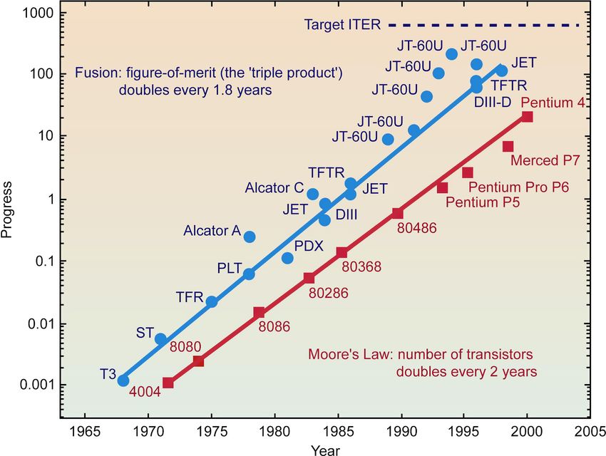
Nuclear Fusion                                                                                                                                      J. S
                                                                                                                                                        anchez

Figure 1. Progress of the fusion triple product Ti.ni.sE.

Table 1. Main ITER parameters.                                                       The challenge in science and technology is formidable
Fusion power                    500 MW                                            but it is not the only one: ITER is also to some extent a
Fusion power gain (Q)           >10 (for 400 sec inductively driven               social experiment. With magnetic fusion research being a
                                 burn)                                            declassified activity both by the eastern and western coun-
                                >5 (1500 sec)                                     tries during the cold war, the undertaking of a large joint
Plasma major radius (R)         6.2 m                                             experiment was one of the agreements between presidents
Plasma minor radius (a)         2.0 m
                                                                                  Reagan and Gorbachev on their summit of November
Plasma vertical elongation      1.70/1.85
                                                                                  1985 at Geneva. The European Union and Japan joined
Plasma current (Ip)             15 MA
Toroidal Field at 6.2 m         5.3 T                                             the project immediately and the design evolved slowly
 radius                                                                           during the following years in a process which included
Installed auxiliary heating     73 MW                                             the temporary withdrawal of the USA and the decision in
Plasma volume                   830 m3                                            1998 to redesign the device in order to make it more
Plasma surface area             680 m2                                            affordable and ended with the delivery of the final design
Plasma cross-section area       22 m2
                                                                                  report in 2001. In 2004, the USA returned to the project
                                                                                  and China and Korea, as well as later India, expressed
                                                                                  their interest to join, which was welcome in order to
                                                                                  share the multibillion costs of the project.
addition, ITER will carry out a number of experiments to                             The main drive for the interest of the parties was fusion
test the technology developments necessary for a power                            energy as a long-term goal, but, in the shorter term, their
plant, in particular, the “breeding blanket” modules                              interest was also focused in the important technology
which will test the technology for tritium generation from                        developments around ITER. This led to an organization
lithium (Fig. 2).                                                                 based on a moderate size central team, located at the pro-
   ITER is a large extrapolation in volume (10 times lar-                         ject site in Cadarache (France) and in charge of about 15%
ger than JET) and also in technology. In addition to the                          of the total ITER budget, and seven, smaller but still strong,
use superconducting coils, cooled at 1.4 K while located                          teams, named “domestic agencies”, located at the different
less than a meter away from the million degree hot                                parties’ headquarters and in charge of delivering in-kind
plasma, the largest challenges come from the goal to                              components to the central team for about 85% of the bud-
operate long pulses at full fusion power: all the internal                        get. Europe as the host party would provide nearly half of
elements need active cooling as well as neutron-resistant                         the total budget and the remaining part would be covered
functional materials, particularly insulators.                                    by the other six parties.

168                  ª 2014 CIEMAT, Spanish Ministry of Economy and Competitiveness. Energy Science & Engineering published by the Society of Chemical Industry
                     and John Wiley & Sons Ltd.
J. S
anchez Nuclear Fusion
Figure 2. Artist view of the ITER device.
The organization based on in-kind contributions led to an estimate for the “first plasma”, which would
allowed for an a priori distribution of the participation mark the end of the construction period, to happen in
and could accommodate the wish of the parties to partici- 2022–23. This delay is the accumulation of several causes:
pate in the technologies of their interest, in addition, this lack of a finalized design, lack of manpower at the central
was the way to allow for the emerging countries to have team imposed by the budget restrictions, delays in Japa-
lower costs by developing components with their own nese components after the 2011 earthquake damaged
workforce. On the other hand, the system, based on a some key facilities, additional licensing requirements
central team which prescribes the design but does not derived from the post–Fukushima revision of all the
have responsibility on the cost of construction of these nuclear procedures, etc., but a significant part of the delay
components and the domestic agencies which have to comes from the extremely complex organization of the
procure and pay for the components, is prone to produce project and the distribution of roles and responsibilities.
internal discussions and delays in the decisions. A typical example is when a component design performed
The ITER agreement was signed 21 years after the idea by the central team is felt as an over specification which
was launched, in November 2006 and the first estimate of rises cost by the domestic agency in charge of the con-
the construction period was 9 years. Soon it became evi- struction: the domestic engineers will come back with
dent that between the report delivered in 2001 and the nec- redesigns aiming to lower the cost while the central ones
essary constructive design there was much more distance will be just worried by confidence in the functional role
than originally estimated. The report had concentrated in of the component, thus entering on a loop with no clear
the main machine parameters, the related physics and the outcome. Many of those organizational problems have
design of the critical high-technology components, but been highlighted by the management assessment report
ITER was a very complex industrial plant, subject to a commissioned recently by the ITER Council.
nuclear license, not as a nuclear power plant but as a In the meantime, the good news is that most of the
nuclear facility, and with a very demanding integration high-tech components like the superconducting coils or
process into the buildings’ design. The consequence of hav- the vacuum vessel, have undergone the final designs, with
ing concentrated on the critical components, necessary to the corresponding design reviews, and the related con-
guarantee the feasibility of the project, but having over- struction contracts have been awarded to industry, which
looked the more conventional parts of the facility was an is so far progressing without known major difficulties.
underestimation of cost, which essentially doubled after an The major technical problem happened with the central
in depth revision, and construction time. solenoid superconducting cable, which in 2012 was show-
Although the cost has been kept within reasonable ing degradation with operation time in the samples
bounds after the 2010 revision, suffering moderate tested. Fortunately, further R&D by the Japanese team in
increases but remaining within the limits of the originally charge of this cable provided, on time for the coils con-
foreseen contingency, the schedule seems difficult to con- struction at the USA, a new design which was successfully
trol. Subsequent revisions of the baseline schedule have tested without showing any degradation.
ª 2014 CIEMAT, Spanish Ministry of Economy and Competitiveness. Energy Science & Engineering published by the Society of Chemical Industry
and John Wiley & Sons Ltd. 169Nuclear Fusion J. S
anchez
Other elements of confidence have been provided from fusion power but they are charged particles which can be
the physics side by the research carried in supporting exper- retained in the plasma by the magnetic field and contrib-
iments around the world. As an example, one of the ute to sustain the plasma temperature. The problem is
elements of concern with the original design of ITER, that, whereas the plasma particles have an average energy
which used a carbon inner wall, was the problem of tritium of 15–30 keV, the alphas are born with an energy of
accumulation in the form of hydrocarbons deposited in 3.5 MeV, hundred times higher, and they would escape
remote parts of the device, which could lead to the require- quickly unless the energy transfer mechanism by means of
ment to stop operation after every few experiments and collisions is efficient enough. Preliminary experiments in
undertake a complex tritium removal procedure. On the JET [6] as well as theoretical predictions show that, very
other hand, the use of carbon, due to its good behavior at likely, the alphas will indeed heat the plasma efficiently,
high temperature and low atomic number, was capital for but the ultimate test will be performed in ITER. With
an efficient operation from the physics point of view and Q = 10, the power generated by fusion will be ten times
no clear alternative was at sight. Fortunately, tests of plasma the heating power injected externally, then the alphas,
operation with a full tungsten wall carried out in the recent which carry 20% of this power will provide twice the
years in the German device ASDEX-U and with a tungsten externally injected heating, leading to a clear effect that
divertor and beryllium wall (the same combination of will serve as a concluding test of the alpha heating.
ITER) in JET have demonstrated reliable efficient operation
without the tritium retention problem. Now ITER has
Toward the Demonstration Reactor
changed its design and the lower part of the inner wall, the
so called “divertor”, where the interaction with the plasma ITER will demonstrate the scientific feasibility of fusion
concentrates, will use tungsten as plasma-facing material. as energy source and will also test key technologies for
In parallel, developments in the control of the periodic the reactor but ITER will not yet be a real power plant.
busts of power to the wall (the so called Edge Localised The main differences between ITER and a demonstration
Modes, ELMs), the progress in the understanding of power plant, the so called “DEMO”, from “demonstra-
energy and particle confinement and its extrapolation to tion”, would be: tritium self-sufficiency, full plant energy
ITER size or the achievement of reliable operation at the efficiency, use of low-activation neutron-resistant materi-
high plasma densities projected for ITER reinforce our als, and reliable continuous operation. In the following
confidence in the operational success of the experiment. pages, we will address the status and perspective of the
Still some of the original concerns remain, for instance related developments.
the need to avoid and mitigate the so called “disrup-
tions”, rapid losses of confinement which could lead to
Tritium Self-Sufficiency
damage of internal components, but progress is steady in
all those fronts. As explained in the introduction, fusion plants would
This situation, with organizational delays in one side need to generate in situ the tritium they will consume by
but smooth progress in the most critical components, and bombarding lithium with the fusion-generated neutrons,
physics projections in the other side, makes us to be rela- through the reaction: n+Li6?T+He4. This function will
tively optimistic toward the actual success of the project be performed by the so called “breeding blanket” which
and encourages us to work in order to find the right will surround the plasma. The breeding blanket has also
organizational frame to avoid further delays. two main additional functions: to extract the power of
With ITER starting operation in 2023, the critical high- the neutrons conveying it to the steam generators and the
gain results with Q = 10 will come shortly before 2030. turbines and to shield the sensitive components, in partic-
One of the answers we expect to get from these experi- ular the superconducting coils, from the neutron flux
ments is the efficiency of the plasma heating by the high- which would heat and damage them. This makes of the
energy He ions generated at the fusion reaction, also breeding blanket a very demanding nuclear component.
called “alpha particles”. This is crucial for the future of ITER will not be equipped with a full breeding blanket,
the tokamak as a fusion reactor because we need to use and therefore it will not be self-sufficient in tritium. The
these alpha particles to maintain the high temperatures current plan is to purchase the tritium that it will con-
which sustain the reaction. In the fusion reaction, neu- sume from an external source, essentially the Canadian
trons carry 80% of the released energy, they cannot be nuclear fission programe, but it will have a number of
retained by the magnetic field, and therefore they cannot smaller blanket modules which will be used to test differ-
contribute to sustain the reaction (in the power plant ent tritium-generation technologies.
their energy will be extracted by the coolant and used to The ITER blanket modules will test different options
drive the turbines). Alphas will carry only 20% of the for the three main elements in a breeding blanket. First,
170 ª 2014 CIEMAT, Spanish Ministry of Economy and Competitiveness. Energy Science & Engineering published by the Society of Chemical Industry
and John Wiley & Sons Ltd.J. S
anchez Nuclear Fusion
there is the choice of breeding material, the main options of the plant, which must take into account all the energy
being molten eutectic lithium–lead, with 90% Li6 enrich- consumption of the coils, cryogenic systems, and other
ment or lithium salt pebbles (Li4SiO4 or Li2TiO3) with auxiliary systems as well as the wall plug efficiency of the
30–60% Li6 enrichment. Secondly, we need a neutron plasma heating systems and the efficiency of the thermal
multiplier, usually beryllium or the lithium–lead itself, cycle. Overall, an efficient power station would require Q
because a fraction of the neutrons generated in the fusion in the order of 50, which means a device with either a
reaction will fail to hit the breeding material. Fortunately, more efficient physics, a higher magnetic field (difficult to
the neutron energy required for the breeding reaction is achieve due to the limitations in the superconductors) or
relatively low and using a neutron multiplier each single a larger size.
14 MeV fusion neutron can generate several secondary Typical European designs of a demonstration fusion
neutrons able to produce tritium. The third element is power plant [9] consider the total fusion power in the
the coolant, which must extract the energy deposited and range of 2000 MW thermal and have a linear size, 1.5
generated in the blanket (the breeding reaction is exother- times of ITER. A device with this size and power is a sig-
mic), here the options are: water cooling, helium cooling, nificant challenge, in particular, on what concerns the
or dual cooling by helium and lithium–lead. [7]. extraction of the power.
The integral test of breeding blanket modules in ITER As explained before, the neutrons carry 80% of the
will be a crucial experiment in order to validate the dif- power, they escape the plasma isotropically and cross the
ferent technologies. The strategic value of those designs is wall of the tokamak and are absorbed volumetrically in
such that the breeding blanket program is not part of the the coolant and blanket structures. The thermal power is
ITER agreement, which foresees that all the knowledge very high but this broadly distributed load can be toler-
generated in the project will be shared among the seven ated by the materials. The neutrons can generate a num-
parties, but a separate activity whose results would be pri- ber of other issues in the materials but the thermal load
vate intellectual property. It has to be coordinated due to is not a serious problem.
the host role of ITER but the information obtained in the On the other hand, the remaining 20% of the power,
experiments will be sole property of the related party and carried by the alpha particles, together with externally
in principle would not be shared. injected power, also carried by charged particles, flows
The European Roadmap toward fusion electricity [8] slowly toward the wall. The magnetic field can delay this
includes a breeding blanket technology programe parallel flow but once the steady state is reached there is a contin-
to the preparation of the validation tests of the ITER uous flux of energy toward the inner wall of the device.
blanket modules. The four technologies selected are the All this power is conveyed to a small fraction of the
two which Europe will test in ITER, lithium–lead, and wall, the so called “divertor”. This is necessary to avoid
ceramic pebbles both cooled by helium, plus two addi- the penetration of sputtered wall particles into the hot
tional options. The water cooled lithium–lead, as a plasma that would quench the high temperature but it
shorter term option, has the advantage of avoiding the generates a serious problem: all this power is deposited in
use of helium, which might become scarce if thousands a narrow, several cm, ribbon along the torus, leading to
of fusion plants need to use it, and the high cooling thermal loads in excess of 20 MW/m2, twice higher than
capacity of water; on the other hand, water generates cor- the current engineering limit.
rosion problems as well as safety issues and its tempera- The possible solutions to what the experts see nowa-
ture operation window (280–325°C) is hardly compatible days as the main challenge toward the success of fusion
with the low-activation neutron-resistant materials which energy, operate from the two sides of the problem: cool-
we have at hand today. The dual coolant, a longer term ing the plasma edge by emission of radiation in the visi-
option uses a faster circulation of the liquid LiPb to use ble and ultraviolet range, which distributes the load over
it as high-temperature coolant. The use of insulating a larger surface, and designing “divertor” geometries and
inserts and an additional helium cooling system allow for materials which can handle the power.
the structural material to remain at lower temperature Cooling of the plasma edge can be achieved by inject-
than the main coolant, which has a much higher temper- ing gases like nitrogen, krypton, and argon [10], the goal
ature and leads to a higher plant efficiency. is that a large fraction of the power is radiated at the edge
while preserving the good core confinement. In addition,
geometries which expand the interaction area in order to
High Gain for Plant Efficiency and the
decrease the power density are being developed, like the
Energy Extraction Problem
“super X” [11] or the “snowflake” [12] divertors. The
The Q = 10 power gain of the ITER plasma will not be final tool to overcome this challenge is the choice of
enough for having a real energy gain in the full balance materials, the basic reference material is tungsten but
ª 2014 CIEMAT, Spanish Ministry of Economy and Competitiveness. Energy Science & Engineering published by the Society of Chemical Industry
and John Wiley & Sons Ltd. 171Nuclear Fusion J. S
anchez
liquid metal alternatives, using lithium, gallium, or tin, decay is also observed for vanadium alloys [13] but vana-
which offer “self-repairing” walls, are also being consid- dium currently lacks industrial development and has
ered. some negative effects, like corrosion, Tritium permeation,
and narrower operating temperature.
One of the problems in the development of materials
Neutron Resistant Materials
for fusion reactors is the absence of intense sources of
The power carried by the neutrons is not a big problem 14 MeV neutrons which could allow us to test the behav-
as explained above, however, the high fluence of ener- ior of the material in similar conditions to those in the
getic 14 MeV neutrons generates a different set of prob- fusion plant [14]. EUROFER has shown good perfor-
lems in the material. The problems will not be present mance under irradiation in fission reactors, which essen-
in ITER, at least for the structural materials, due to the tially reproduce the dpa’s effect but there is little
relatively low accumulated neutron fluence, but will be knowledge about the effect of He and H accumulation.
very severe for DEMO and for the commercial fusion One possibility is to use theoretical modeling of the
plants. irradiation effects. Activation is relatively easy to deter-
Firstly, each neutron impact will give rise to a cascade mine, as it essentially depends on the concentration of
of collisions which will displace many atoms from their the different elements and neutron propagation calcula-
positions. This is measured on “displacements per atom” tions are possible. However, the structural changes are
or dpa’s, one dpa meaning that, on average, every atom nearly impossible to compute starting from first princi-
within the material has been displaced once. The struc- ples: we are in a problem where the number of particles
tural material of the blanket and first wall in a fusion is in the order of Avogadro’s number and the changes
reactor will suffer an excess of 100 dpa’s during the com- must be tracked in picoseconds scale for periods of many
ponent lifetime, in addition, the 14 MeV neutrons, dis- seconds (which are the characteristic times of the changes
tinctly to the neutrons in a standard fission reactor, will in the mechanical properties). The modeling is performed
generate transmutation reactions in the material which using a multiscale approach, but the approximations are
will produce helium and hydrogen and create blisters as such that the experimental tests of every scale model as
well as material swelling. All these phenomena can well as an overall test of the complete modeling are neces-
degrade significantly the mechanical properties of the sary.
material, but there is one more adverse effect: the irradi- A family of 14 MeV neutron sources under consider-
ated material becomes radioactive and will have to be ation is based on the use of reduced size fusion reactors
treated as radioactive waste. with modest Q but with substantial DT reaction rate sus-
The materials which adapt best to the 14 MeV neutron tained by external injected power and equipped with a
bombardment are: vanadium alloys, titanium alloys, sili- full breeding blanket in order to self generate the tritium.
con carbide, a long-term promise but still difficult to use The so called CTF’s (Component Test Facilities) belong
as structural material and, the current reference material to this family and there are several proposals under study
which has achieved the highest technological maturity, both in the China and the USA [15–17].
the RAFM (Reduced Activation Ferritic-Martensitic) The second family of sources is based on accelerator-
steels. As iron is relatively resilient to neutron bombard- driven neutron generation. For example, the reference
ment and suffers little activation, RAFM steels, like the proposal, IFMIF (International Fusion Materials Irradia-
Japanese F82H or the European EUROFER, are based on tion Facility) considers two 40 MeV deuteron beams of
the suppression of problematic impurities (Ni, Cu, Al, Si, 125 mA each which hit a liquid lithium target producing
Co, etc.) and the substitution of problematic alloying a neutron spectrum very similar to that of a fusion reac-
components (Mo, Nb) by other elements which play the tor. IFMIF, a 1500 M€ project, would produce 20–
same chemical role in the alloy but have a more benign 50 dpa/year in a reduced volume of 0.5 L and smaller
nuclear behavior (Ta, W). RAFM steels would suffer less rates in the wider adjacent space. It is considered as the
activation than the standard ones although they would ultimate tool to qualify materials for the fusion power
still be an activated material after decommissioned from plants. Currently, Europe and Japan are carrying valida-
the fusion reactor. The current studies foresee that the tion developments for IFMIF components and a complete
components could be recycled after ~100 years under cus- accelerator with all the basic elements will be tested in
tody as medium-low level radioactive waste, as opposed Rokkasho (Japan) in 2017. The possibility to use this pro-
to ~100,000 years for standard steel components under totype accelerator in an early reduced version of IFMIF is
equivalent conditions. The possibility to further reduce currently gaining momentum. This source could be avail-
this period depends on the level of impurity suppression able by the early 2020’s in order to qualify components at
technically, and economically, achievable. A fast activation 20 dpa for an earlier phase of DEMO.
172 ª 2014 CIEMAT, Spanish Ministry of Economy and Competitiveness. Energy Science & Engineering published by the Society of Chemical Industry
and John Wiley & Sons Ltd.J. S
anchez Nuclear Fusion
In the meantime, the fusion materials programe is
strongly involved in the development of new materials
and the consolidation of the reference ones, for example,
one of the current limitations of EUROFER type steels is
their reduced operation temperature window (350–
550°C) which might be expanded by using ODS (Oxide
Dispersion Strengthened) versions with yttrium oxide.
Limited irradiation tests are also carried in fission reactors
(use of boron doped material or the inclusion of some
amount of 56Fe can simulate the He generation by
14 Mev neutrons) or using multiple ion beams to pro-
duce simultaneous dpa’s and He/H implantation, at a
very fast rate but in very reduced sample volumes. Those
experiments can complement the theoretical models as
well.
Maintenance Issues and Plant
Systems
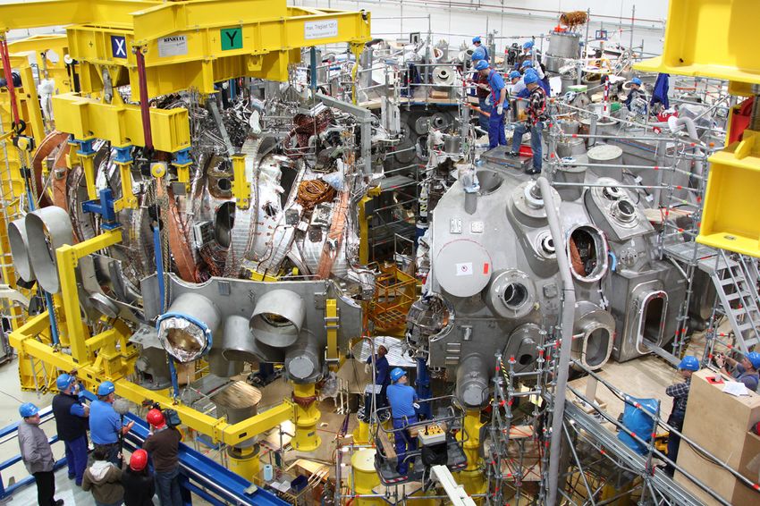
RAMI (Reliability, Availability, Maintainability, and In- Figure 3. JET remote handling system.
spectability) will be a key issue in a complex facility as a
fusion power plant if we want it to operate under eco- inducing a strong electric current in the highly conductive
nomically sustainable conditions. In particular, given the hot plasma. With this contribution from the plasma,
fact that the structure will become activated soon after some complex additional magnets that otherwise would
the start of operation, most maintenance operations will be necessary are spared. The current also contributes to
have to be done by remote control manipulation. This heating the plasma by Joule effect. This solution offers
means that all components inside the vacuum vessel and some advantages and disadvantages as compared with the
many of the components inside the cryostat, even for other family of devices, the “stellarator” which assumes
ITER, will have to be designed compatible with Remote no help from the plasma and configures the complete
Handling (RH) operations: size and weight of the compo- magnetic field by means of additional 3-dimensionally
nents, assembly method, assembly sequence, interfaces shaped magnets.
with the RH tools. . .etc. Today, devices like JET have The advantages of the tokamak: comparative simplicity
shown the feasibility of complex RH operations like the and very good confinement properties, makes this config-
full substitution of the divertor or the first wall (see uration the best option for a fusion ignition prototype
Fig. 3), however, the replacement times need to be signifi- like ITER or even a first DEMO device, however, the
cantly shortened in a commercial reactor and this would tokamak has also some limitations derived from the
imply to evolve from today’s man-driven operation to strong coupling of the plasma and its confinement. First
automatic operation for many of the actions. of all, the plasma current (up to 15 MA on ITER) is usu-
A lot of technology development would also be ally induced with a transformer effect, which is impossible
required in plant systems: tritium extraction, isotope sep- to sustain in steady state. Today’s tokamaks are pulsed
aration systems, He, and liquid metal heat exchangers, as devices and this might have implications on the manage-
well as advanced thermal cycles are among the systems ment of the supply to the electric network and the com-
which are currently being developed as part of the fusion ponents fatigue when used as a power plant. Some
technology programes worldwide. progress has been achieved in the development of nonin-
ductive current drive systems, but there is still a long way
ahead in the path toward the complete steady state. The
Steady State Reactors: The
second problem, derived from the plasma–confinement
Stellarator
coupling, is the existence of scenarios where plasma and
The “tokamak” concept, on which ITER and most fusion confinement drop suddenly together in a very fast
devices are based, is a very clever design with optimal positive feedback process (milliseconds) which ends in a
confinement properties. In this configuration, the con- tremendous thermal release to the wall and the quench of
fined plasma contributes itself to the construction of the the >10 MA plasma current. In these events, called “dis-
confining magnetic configuration, this is achieved by ruptions”, very strong electromagnetic forces are
ª 2014 CIEMAT, Spanish Ministry of Economy and Competitiveness. Energy Science & Engineering published by the Society of Chemical Industry
and John Wiley & Sons Ltd. 173Nuclear Fusion J. S
anchez
generated and jets of fast electrons can achieve multi which could be used either in a pure fission reactor, in
MeV energy, becoming a potential threat for the integrity this case the fusion system would be a way to produce fis-
of the internal components. sion fuel, or in the fusion reactor blanket playing the role
On the other hand, Stellarators are inherently steady of energy amplification. The same DT neutrons could be
state devices which could operate under stationary condi- used to just irradiate and “burn” the nuclear radioactive
tions for months and stop only for maintenance pur- waste accumulated during the complete history of fission
poses. As the confinement is decoupled from the plasma, energy generation.
stellarators are also free of disruptions. Those three applications have intermittently gained and
Stellarators are, in fact, older than tokamaks, first lost attention since the idea was conceived in the 19500 s
devices were developed by Spitzer in the early 19500 s, but and later relaunched by H. Bethe in 1979 [18]. In princi-
the simplicity and good results of the tokamak soon rele- ple, a fusion gain Q = 5, complemented with a 109
gated them to a secondary role. In the 19800 s, new design amplification from the fission blanket would suffice for
tools and constructive techniques, together with the intro- having an efficient power plant, which means that from
duction of radiofrequency plasma heating systems which the fusion side, a device like ITER, and even a bit smaller,
could substitute the traditional Joule heating based on could do the job. Those who support the idea see as the
plasma current, allowed for a relaunching of the stellara- main advantage the simplification of the fusion core and
tors and the results from devices like the German W7AS a faster process toward energy generation. For those
and the Japanese LHD, a superconductor-based device, opposing, the hybrids just bring together all the problems
have shown the strong potential of this configuration, of fusion, in particular complexity, and fission: less waste
overcoming the main limitations in confinement that hin- but still significant, proliferation, handling of highly active
dered the progress with earlier devices. In 2015, the large material. A very interesting discussion, which includes the
superconducting stellarator W7X (Fig. 4), currently under opinion of a “skeptics group”, can be found in ref. [19].
construction in Greifswald (Germany), will start opera- Currently, there is no effort on hybrids in the European
tion. The results of this experiment might strongly rein- Roadmap, which focus on “pure fusion”, but there are
force the potential of the stellarator as a long-term option active groups in China and the USA and significant activ-
for the commercial reactor units, on which the engineer- ity and interest have been reported by the Russian prog-
ing complexity will play a secondary role compared with rame [20].
the simplicity and smoothness of the operation.
The Roadmap to Fusion Electricity
Fission– Fusion Hybrid Systems
The parallel effort of ITER and the technology programes
The 14 MeV DT fusion neutrons can be used to irradiate should converge in the construction of a DEMO power
uranium 238 or thorium 232 and generate fissile material, reactor. The concept of DEMO varies in the different
Figure 4. Assembly process of the W7X stellarator.
174 ª 2014 CIEMAT, Spanish Ministry of Economy and Competitiveness. Energy Science & Engineering published by the Society of Chemical Industry
and John Wiley & Sons Ltd.J. S
anchez Nuclear Fusion
Milestones
JET ITER
ITER Q=10
Inductive ITER steady Decisions
1. Plasma operation Steady state regimes state
Experiments
Medium Sized Tokamaks
ITER
JT60
DTT ITER
ITER Q=10
Baseline strategy
2. Heat Exhaust Advanced configuration and materials
Medium Sized Tokamaks, linear plasma devices and Divertor Tokamak Test Facility (DTT)
Early Neutron Source
IFMIF
3. Materials
ITER
ITER Q=10
ITER TBM
4. Tritium breeding Programme
Parallel Blanket Concepts
Fusion Engineering Testing Reactor (CFETR, CN) and Fusion Neutron Science facility (FNS, US)
ITER
5. Safety
DEMO Fusion Electricity
ITER
6. DEMO Component Design and Eng. Design Construction Operation
7. Low cost Low capital cost and long term technologies
W7X
8. Stellarator Stellarator optimisation Burning Plasma Stellarator
2010 2020 2030 2040 2050
Figure 5. European Fusion roadmap [8].
world programes and it is not even clear whether DEMO With the ITER high Q experiments foreseen for the late
would be a single worldwide collaborative experiment like 2020’s and the results of the 20 dpa materials irradiation
ITER or several competing developments running in par- available by the same dates, the DEMO construction
allel in different countries, looking for a leading position could start by the mid 2030’s and should be able to start
in a phase where the economic profit of fusion might be net electricity generation before 2050 (Fig. 5). By that
at sight. time, we expect that the materials irradiation facility IF-
The European DEMO concept [21] sees the device as MIF would have been built and provided the necessary
the last experimental facility before industry takes the lead data for full qualification of low-activation structural
in the construction of commercial fusion plants. As materials under >100 dpa’s. Those data might also be
described above, it should be self-sufficient in tritium, use complemented with results from the current projects for
advanced low-activation materials and provide in the CTF. From this point, we will enter the situation where
order of 500 MW of net electricity to the grid during private investors and industry will engage in the construc-
operational periods of several weeks. tion of the first commercial plants. When will this happen
ª 2014 CIEMAT, Spanish Ministry of Economy and Competitiveness. Energy Science & Engineering published by the Society of Chemical Industry
and John Wiley & Sons Ltd. 175Nuclear Fusion J. S
anchez
is difficult to predict, it will depend on the energy market 10. Kallenbach, A., M. Bernert, R. Dux, L. Casali, T. Eich, L.
situation and the overall energy supply scenario, but given Giannone, et al. 2013. Impurity seeding for tokamak
the size and potential profits of the energy market, (the power exhaust: from present devices via ITER to DEMO.
full cost of ITER construction, estimated 12–15 billion Plasma Phys. Controlled Fusion 55, art. no. 124041
euro, is about the cost of one single day of worldwide 11. Kotschenreuther, M., P. Valanju, S. Mahajan, L. J. Zheng,
energy consumption) we expect that this might be a rela- L. D. Pearlstein, R. H. Bulmer, et al. 2010. The super X
tively fast development, leading to a significant share of divertor (SXD) and a compact fusion neutron source
fusion in the energy mix during the second half of the (CFNS). Nucl. Fusion 50, art. no. 035003
century. 12. Ryutov, D. D., R. H. Cohen, T. D. Rognlien, and M. V.
Umansky. 2012. A snowflake divertor: a possible solution
to the power exhaust problem for tokamaks. Plasma Phys.
Conflict of Interest Controlled Fusion 54, art. no. 124050
None declared. 13. Zucchetti, M., S. A. Bartenev, A. Ciampichetti, and R.
Forrest. 2007. A zero-waste option: recycling and clearance
References of activated vanadium alloys. Nucl. Fusion 47:S477–S479.
14. Zinkle, S. J., and A. M€ oslang. 2013. Evaluation of
1. Freidberg, J. P. 2007. P. 12 in Plasma physics and fusion irradiation facility options for fusion materials research
energy. Cambridge University Press, New York, NY. and development. Fusion Eng. Des. 88:472–482.
2. Hurricane, O. A., D. A. Callahan, D. T. Casey, P. M. 15. Wan, Y. 2012. Mission & readiness of a facility to bridge
Celliers, C. Cerjan, E. L. Dewald, et al. 2014. Fuel gain from ITER to DEMO. 1st IAEA-DEMO Program
exceeding unity in an inertially confined fusion implosion. workshop, Los Angeles, USA, October 15–18.
Nature 506:343–347. 16. Peng, Y. K. M., J. M. Canik, S. J. Diem, S. L. Milora, J. M.
3. Rebut, P.-H, and the JET Team. 1992. The JET Park, A. C. Sontag, et al. 2011. Fusion nuclear science
preliminary tritium experiment. Plasma Phys. Control. facility (FNSF) before upgrade to component test facility
Fusion 34: 1749. (CTF). Fusion Sci. Technol. 60:441–448.
4. Keilhacker, M., A. Gibson, C. Gormezano, P. J. Lomas, P. 17. Wong, C. P. C., V. S. Chan, A. M. Garofalo, J. A. Leuer,
R. Thomas, M. L. Watkins, et al. 1999. High fusion M. E. Sawan, J. P. Smith, et al. 2011. Fusion nuclear
performance from deuterium-tritium plasmas in JET. science facility – advanced tokamak option. Fusion Sci.
Nucl. Fusion 39:209–234. Technol. 60:449–453.
5. Strachan, J. D., S. Batha, M. Beer, M. G. Bell, R. E. Bell, A. 18. Bethe, H. 1979. The fusion hybrid. Phys. Today 32:44–51.
Belov, et al. 1997. TFTR DT experiments. Plasma Phys. 19. Freidberg, J.P., Fink, Ph, et al. 2009. Fusion-Fission
Controlled Fusion 39:B103–B114. Research Workshop (2009) September 30–October 2,
6. Thomas, P. R., P. Andrew, B. Balet, D. Bartlett, J. Bull, B. Gaithersburg, MD (USA). Available at http://web.mit.edu/
De Esch, et al. 1998. Observation of alpha heating in JET fusion-fission/ (accessed 04 07 2014).
DT plasmas. Phys. Rev. Lett. 80:5548–5551. 20. Azizov, E. A., G. G. Gladush, and E. P. Velikhov. 2013.
7. Giancarli, L. M., M. Abdou, D. J. Campbell, V. A. Project development of experimental hybrid reactor on the
Chuyanov, M. Y. Ahn, M. Enoeda, et al. 2012. Overview of basis of a compact tokamak for the disposal of spent
the ITER TBM program. Fusion Eng. Des. 87:395–402. nuclear fuel. Proceedings 21st International Conference on
8. Romanelli, F., P. Barabaschi, D. Borba, G. Federici, L. Nuclear Engineering, July 29–August 2, Chengdou, China.
Horton, R. Neu, et al. 2012. A roadmap to the realisation 21. Federici, G., R. Kemp, D. Ward, C. Bachmann T.
of fusion energy. EFDA document available at http://www. Franke, S. Gonzales, C. Lowry, M. Gadomska, J.
efda.org/wpcms/wp-content/uploads/2013/01/JG12. Harman, B. Meszaros, C. Morlock, F. Romanelli, and R
356-web.pdf Wenninger. 2014. Overview of EU DEMO design and
9. Maisonnier, D., I. Cook, P. Sardain, L. Boccaccini, L. Di R&D activities, Fusion Engineering and Design 89:882–
Pace, L. Giancarli, et al. 2006. DEMO and fusion power 889.
plant conceptual studies in Europe. Fusion Eng. Des.
81:1123–1130.
176 ª 2014 CIEMAT, Spanish Ministry of Economy and Competitiveness. Energy Science & Engineering published by the Society of Chemical Industry
and John Wiley & Sons Ltd.You can also read