Energy & Environmental Science

Page created by Melvin Pratt
 
CONTINUE READING
Energy & Environmental Science
Volume 15
                                                                            Number 5

Energy &
                                                                            May 2022
                                                                            Pages 1699–2166

Environmental
Science
rsc.li/ees

             ISSN 1754-5706

             PAPER
             Juan F. Torres, Kaoru Tsuda, Joe Coventry et al.
             Highly efficient and durable solar thermal energy harvesting
             via scalable hierarchical coatings inspired by stony corals
Energy & Environmental Science
Energy &
                                                                                                               Environmental
                                                                                                               Science
           This article is licensed under a Creative Commons Attribution-NonCommercial 3.0 Unported Licence.

                                                                                                                                                                                                                                                        View Article Online
                                                                                                                   PAPER                                                                                                                                View Journal | View Issue

                                                                                                                                                          Highly efficient and durable solar thermal energy
                                                                                                                                                          harvesting via scalable hierarchical coatings
                                                                                                               Cite this: Energy Environ. Sci.,
Open Access Article. Published on 28 March 2022. Downloaded on 6/19/2022 7:11:45 PM.

                                                                                                               2022, 15, 1893                             inspired by stony corals†
                                                                                                                                                          Juan F. Torres,            *a Kaoru Tsuda,*b Yasushi Murakami,c Yifan Guo,                                  a
                                                                                                                                                                                     a
                                                                                                                                                          Sahar Hosseini,               Charles-Alexis Asselineau, a Mahdiar Taheri,                              a
                                                                                                                                                                                                                                                                      Kurt Drewes,d
                                                                                                                                                                                     ef
                                                                                                                                                          Antonio Tricoli,              Wojciech Lipiński a and Joe Coventry *a

                                                                                                                                                          Concentrating solar thermal (CST) is an efficient renewable energy technology with low-cost thermal
                                                                                                                                                          energy storage. CST relies on wide-spectrum solar thermal absorbers that must withstand high
                                                                                                                                                          temperatures (4600 1C) for many years, but state-of-the-art coatings have poor optical stability. Here,
                                                                                                                                                          we show that the largely overlooked macro-scale morphology is key to enhancing both optical
                                                                                                               Received 26th September 2021,              resilience and light trapping. Inspired by stony-coral morphology, we developed a hierarchical coating
                                                                                                               Accepted 9th March 2022                    with three tuneable length-scale morphologies: nano- (B120 nm), micro- (B3 mm) and macro-scales
                                                                                                               DOI: 10.1039/d1ee03028k                    (450 mm). Our coating exhibits outstanding, stable solar absorptance of 497.75  0.04% after ageing at
                                                                                                                                                          850 1C for more than 2000 hours. The scalability of our coating is demonstrated on a commercial solar
                                                                                                               rsc.li/ees                                 thermal receiver, paving the way for more reliable high-performance solar thermal systems.

                                                                                                                   Broader context
                                                                                                                   The impact of anthropogenic climate change is being experienced across the globe. Renewable energy technologies are widely regarded as key to reducing
                                                                                                                   greenhouse gas emissions and thus mitigating the devastating effects of climate change. Concentrating solar thermal (CST) is an important technology in that
                                                                                                                   mix, owing to its low-cost thermal energy storage that can be used to drive many essential processes, from electricity generation to steel production. Vital to the
                                                                                                                   wide adoption of CST is achieving high stability and efficiency of its photo-thermal energy conversion process, which generally occurs on a solar absorber
                                                                                                                   coating. However, due to the extreme operation conditions of high-temperature and high-flux, state-of-the-art coatings degrade in performance rapidly, and
                                                                                                                   often fail completely. Here, inspired by stony coral morphology, we report a hierarchical coating that incorporates advances in materials design and
                                                                                                                   architecture to mitigate coating degradation and increase photo-thermal energy conversion. Our coral-inspired coating demonstrates ultra-high stability after
                                                                                                                   ageing in air at elevated temperatures (Z800 1C), and has the highest reported sunlight absorptance. We show that the coating is scalable on commercial
                                                                                                                   receivers and yields a significant improvement in photo-thermal efficiency for large-scale CST power plants. This work paves the way for more reliable high-
                                                                                                                   performance solar thermal systems.

                                                                                                               Introduction                                                                           nutrients in otherwise infertile waters1 and thrive in all Earth’s
                                                                                                                                                                                                      oceans. Sunlight attenuation in seawater initially restricted
                                                                                                               Scleractinia, commonly known as stony corals (Fig. 1a), have                           coral colonies to shallow waters.2,3 To thrive in deeper waters
                                                                                                               evolved their morphology over millions of years to improve                             where light is more scarce, coral morphology4 has evolved to
                                                                                                               their chances of survival. A symbiotic relationship with algae,                        improve light trapping5 via multiple internal light reflections
                                                                                                               which need sunlight for photosynthesis, was an evolutionary                            (Fig. 1b and c). We can then learn from stony-coral morphology
                                                                                                               milestone 240 million years ago that enabled corals to secure                          in engineering and science where light trapping is needed,
                                                                                                                                                                                                      including sunlight harvesting using concentrating solar ther-
                                                                                                               a
                                                                                                                 College of Engineering and Computer Science, Australian National University,         mal (CST) systems.6,7 Absorber coatings applied to solar recei-
                                                                                                                 Canberra, Australia. E-mail: felipe.torres@anu.edu.au, joe.coventry@anu.edu.au       vers in CST plants have the function of converting concentrated
                                                                                                               b
                                                                                                                 Nano Frontier Technology, Tokyo, Japan. E-mail: kaoru.tsuda@nano-frontier.com        sunlight in a wide-spectrum into thermal energy8 for many
                                                                                                               c
                                                                                                                 Faculty of Textile Science and Technology, Shinshu University, Ueda, Japan
                                                                                                               d
                                                                                                                                                                                                      applications, including electric power generation (Fig. 1d).9,10
                                                                                                                 Vast Solar, Sydney, Australia
                                                                                                               e
                                                                                                                 College of Science, Australian National University, Canberra, Australia
                                                                                                                                                                                                      Importantly, CST incorporates thermal energy storage, a more
                                                                                                               f
                                                                                                                 Faculty of Engineering, University of Sydney, Sydney, Australia                      affordable, scalable, and durable alternative than other well-
                                                                                                               † Electronic supplementary information (ESI) available. See DOI: 10.1039/d1ee03028k    known storage technologies for long duration energy storage.11

                                                                                                               This journal is © The Royal Society of Chemistry 2022                                                         Energy Environ. Sci., 2022, 15, 1893–1906 | 1893
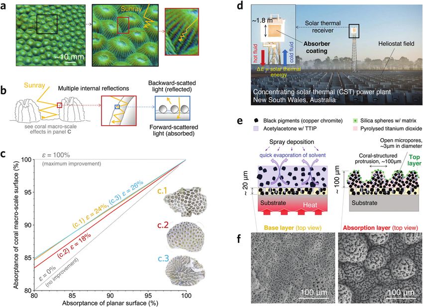
Energy & Environmental Science
View Article Online

                                                                                                               Paper                                                                                                            Energy & Environmental Science
           This article is licensed under a Creative Commons Attribution-NonCommercial 3.0 Unported Licence.
Open Access Article. Published on 28 March 2022. Downloaded on 6/19/2022 7:11:45 PM.

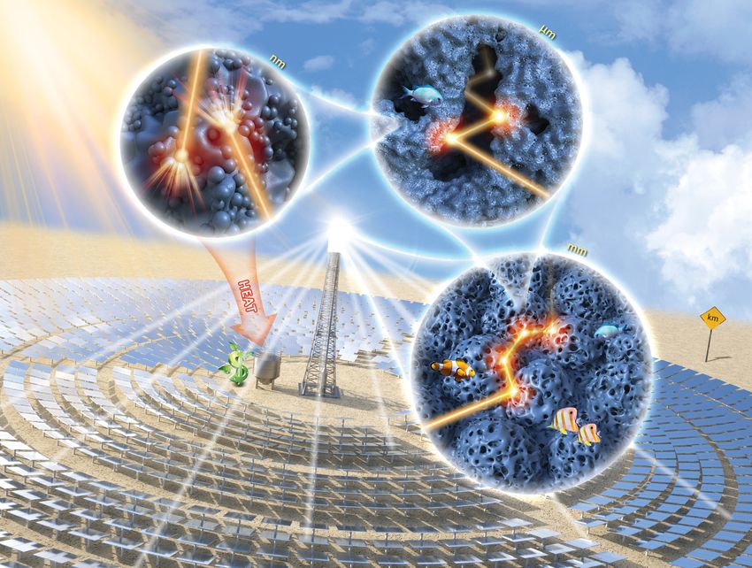
                                                                                                               Fig. 1 A coral-inspired high-temperature solar absorber coating. (a) Photo of a common stony coral (genus Montastraea) showing lumpy macro-scale
                                                                                                               protrusions with smaller features (see other stony coral species in Fig. S1a–c, ESI†). Light trapping is improved via multiple internal reflections. (b)
                                                                                                               Schematic illustrating the different optical interactions occurring within a hierarchical coral structure; the light–matter interaction for the smaller length-
                                                                                                               scale features results in forward and backward scattering. (c) Ray-tracing simulation results showing the increment of absorptance in three coral macro-
                                                                                                               scale morphologies when applying a planar surface absorptance; the effectiveness e in reducing reflection loss (see definition in Methods) for each
                                                                                                               morphology is indicated and independent of the planar surface absorptance. Insets show photos of modelled coral morphologies; an example of surface
                                                                                                               analysis is shown in Fig. S1d–f (ESI†). (d) CST power plant of Vast Solar in Australia where the scalability of the proposed coating is demonstrated on a
                                                                                                               commercial solar thermal receiver (inset). (e) Proposed coating having a B20 mm thick base layer with open micropores of B3 mm in diameter, an
                                                                                                               absorption layer having lumps of 450 mm in diameter resembling corallites in scleractinias, and a top layer with silica matrix and spheres of B120 nm in
                                                                                                               diameter. (f) Scanning electron microscopy (SEM) images of the base (left) and the absorption (right) layers.

                                                                                                                  A key barrier to the wide adoption of CST, contributing to                    ageing for 2000 h at 800 1C,15 and 96.3% after ageing for 3800 h
                                                                                                               both increasing cost and reducing performance, is the poor                       at 770 1C.13 However, unstable optical performance is generally
                                                                                                               durability of its light-absorbing coatings.12 These coatings need                observed in CST coatings because the elevated temperatures
                                                                                                               to withstand high temperatures (4600 1C) and thousands of                        re-arrange the material phases,17 alter the material com-
                                                                                                               thermal cycles over many years of operation.13 The most widely                   position,12,13 modify the nano-scale morphology via sintering
                                                                                                               used CST coatings are spinel-based coatings (Note 1, ESI†) such                  and crystal grain growth,18 and may change large-scale mor-
                                                                                                               as Pyromark 2500s (henceforth referred to as Pyromark),14                        phological features due to the growth of an oxide layer between
                                                                                                               which is considered the gold-standard in the CST industry.                       the coating and metallic substrate,13 e.g. by peeling off.
                                                                                                               These coatings implement an organic binder15 that decom-                         Advanced sunlight absorbers made of carbon nanotubes19 and
                                                                                                               poses during a curing process to produce a nano-textured                         graphene20 can absorb more than 99% of solar irradiation from
                                                                                                               porous coating with spinel pigments, without macro-scale                         every angle, but these coatings burn at the surface temperatures
                                                                                                               (450 mm) features. Solar absorptance, the key performance                        commonly found in conventional receivers.21
                                                                                                               metric,12,16 is typically reported after long-term isothermal                       Most coating research so far has focused on texturing the
                                                                                                               exposure at high temperature, with the highest reported values                   nano-scale morphology and improving the thermal stability of
                                                                                                               being 94.6% after ageing for 2350 h at 850 1C,14 97.2% after                     the materials,12–15,22–24 while neglecting the micro- (B3 mm)

                                                                                                               1894 | Energy Environ. Sci., 2022, 15, 1893–1906                                                  This journal is © The Royal Society of Chemistry 2022
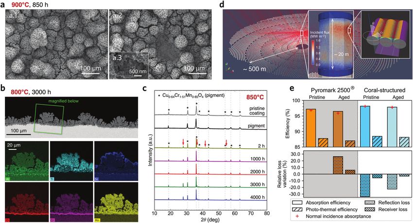
Energy & Environmental Science
View Article Online

                                                                                                               Energy & Environmental Science                                                                                                      Paper

                                                                                                               and macro-scale (450 mm) geometries25 and the tuning of              Results and discussion
                                                                                                               various length-scale morphologies in the coating to maximise         Coral-inspired coating with hierarchical light-trapping
                                                                                                               light absorptance. State-of-the-art surface texturing methods        structure
                                                                                                               in CST coatings include the use of sacrificial beads with
           This article is licensed under a Creative Commons Attribution-NonCommercial 3.0 Unported Licence.

                                                                                                               pre-selected sizes that burn during curing, thus introducing         A hierarchical light-trapping coating is developed with three
                                                                                                               the desired microporosity in the coating,15,26,27 and photolitho-    length-scale morphologies: nano- (B120 nm), micro- (B3 mm),
                                                                                                               graphy-based methods that can yield highly accurate surface          and a macro-scale (450 mm). Our proposed hierarchical struc-
                                                                                                               morphologies.12,28 However, methods based on sacrificial             ture has a large hierarchical range with a ratio of largest to
                                                                                                               beads often lead to highly porous coatings that may weaken           smallest length-scale feature of ca. 800, which is in stark contrast
                                                                                                               their mechanical strength. Photolithography-based methods            with the only other theoretically proposed bio-inspired hierarch-
                                                                                                                                                                                    ical absorber for CST37 whose ratio is ca. 3. A wide-range multi-
Open Access Article. Published on 28 March 2022. Downloaded on 6/19/2022 7:11:45 PM.

                                                                                                               can produce highly dense layers with micro-textured morphol-
                                                                                                               ogy, but the scalability is a major issue due to the vacuum          length scale morphology can be key to enhancing sunlight
                                                                                                               requirements for deposition on tubes larger than 3 m.28 Solar        absorption and optical resilience. To explore the benefits of
                                                                                                               thermal receivers with tube lengths larger than 10 m are             the coral-structured morphology, we model the improvement
                                                                                                               common in the industry.29 Besides, these methods have largely        of light trapping in three species of stony corals. Simulation
                                                                                                               focused on introducing spectral selectivity, i.e. increasing solar   results (Fig. 1c) show that the analysed coral morphologies
                                                                                                               absorption in the visible range while reducing thermal emis-         reduce the reflection loss by 18–26% (see definition of effective-
                                                                                                               sion in the infrared range (Kirchhoff’s law states the equiva-       ness in Methods), while exhibiting an intrinsic optical resilience.
                                                                                                               lence between spectral absorptance and emittance). However, it       That is, even if the absorptance of the flat surface decreases
                                                                                                               has been reported that for high-flux high-temperature applica-       (horizontal axis in Fig. 1c), it is compensated by multiple light
                                                                                                               tions, highly absorptive coatings can achieve the same or even       reflections at the macro-scale level in the coral structure (Fig. 1b)
                                                                                                               better performance than spectrally selective ones.30,31 There-       as evidenced by the increased absorptance (vertical axis). In
                                                                                                               fore, in this work, we focus on increasing the sunlight absorp-      contrast to nano-scale features that are more susceptible to
                                                                                                               tance of the coating (before and after ageing) for the entire        change under high temperature, micro- and macro-scale features
                                                                                                               wavelength spectrum via multi-length scale light trapping to         are mostly unaffected. Multi-length scale design of a light-
                                                                                                               maximise photo-thermal energy conversion, even if there is a         absorbing coating including macro-scale features has not been
                                                                                                               penalty due to thermal emission.                                     reported in the CST literature. In addition to light trapping, such
                                                                                                                  Furthermore, all CST-based electric power generation—             a morphology could have other benefits including mechanical
                                                                                                               which is the targeted application of our coating—has working         strength improvement and drag reduction (see Note 2, ESI†).
                                                                                                               temperatures below 800 1C.9 Even for high-performance solar              The proposed coating has a novel three-layer structure
                                                                                                               thermal receivers using liquid sodium as heat transfer fluid,32      comprised of a base layer, an absorption layer, and a top layer
                                                                                                               the peak absorber surface temperature has been reported to           (Fig. 1e), each having a contribution to both light absorptance and
                                                                                                               be approximately 830 1C. Hence, the targeted temperature             durability. The base and absorption layers contain black spinel
                                                                                                               application of our coating is below 850 1C. Note that larger         pigments (Cu0.64Cr1.51Mn0.85O4) bonded by alumina (Al2O3) and
                                                                                                               temperatures can be tested to accelerate the degradation.            titania (TiO2), respectively. Regarding the contributions to absorp-
                                                                                                               Improvement of receiver coatings for such large temperatures         tance, the base layer has open micropores with light-trapping
                                                                                                               has been identified as one of the top priorities in the CST          features, such as in the coral of Fig. 1c.1. The absorption layer
                                                                                                               community.33 High-temperature solar absorbers that can with-         exhibits a self-assembled morphology with macro-scale protru-
                                                                                                               stand temperatures above 1300 1C have been developed,34              sions, such as the coral in Fig. 1c.2, having the same open
                                                                                                               but these are limited to special corrosive-resistance substrates     micropores as the base layer. Hence, both micro- and macro-
                                                                                                               with a similar thermal expansion coefficient to the coating.           scale morphologies can introduce the intrinsic optical resilience
                                                                                                               These types of substrates are yet to be adopted in the               observed in stony corals. The top layer is a nano-textured surface
                                                                                                               CST industry due to their inferior strength compared to              that contributes to light absorption via enhanced forward scatter-
                                                                                                               superalloys. For the absorber coating to have a tangible impact      ing and optical resonance38,39 induced by B120 nm silica nano-
                                                                                                               on CST technologies, the tested substrate should be a material       spheres and a B8 nm matrix (Fig. S3–S6, ESI†). Regarding the
                                                                                                               that can withstand high peak fluxes and thermal stresses,            contributions to durability, the base layer helps mitigate coating
                                                                                                               such as iron- or nickel-based alloys (e.g. stainless steel and       delamination because the alumina binder adheres well to the
                                                                                                               Inconel).                                                            substrate while the open micropores produce disjoint features that
                                                                                                                  Hierarchical structures have been shown to be a powerful          prevent the propagation of local failures. The absorption layer is
                                                                                                               tool to improve radiative cooling in clothing,35 as well as          comprised of a robust and dense titania binder (Fig. S7, ESI†). The
                                                                                                               mechanical rigidity and stability in sea sponges.36 Here, we         chromium-based spinels in both base and absorption layers con-
                                                                                                               show that a hierarchical design with coral-inspired micro- and       tribute to the formation of a thick substrate-protecting chromium
                                                                                                               macro-scale features can produce high-temperature solar              oxide layer (Fig. S7, ESI†).13 The silica matrix in the top layer is
                                                                                                               absorbers with enhanced light absorption and outstanding             thought to help prevent pigment loss after crystal grain growth.
                                                                                                               optical resilience, which we define as the capacity to retain            The proposed coating is made via a simple and scalable
                                                                                                               stable optical properties despite material degradation.              deposition process (Fig. 1e) that yields tuneable length-scale

                                                                                                               This journal is © The Royal Society of Chemistry 2022                                  Energy Environ. Sci., 2022, 15, 1893–1906 | 1895
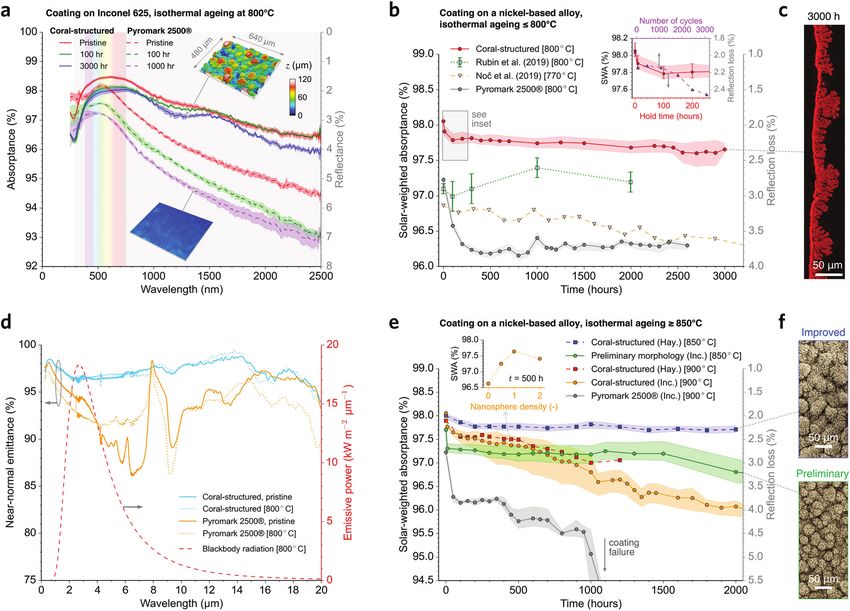
Energy & Environmental Science
View Article Online

                                                                                                               Paper                                                                                                           Energy & Environmental Science

                                                                                                               morphologies. Our coating uses commercially available materi-                   and Ti (from the desorbed solvent), resulting in a matrix
                                                                                                               als and processes that are easily accessible, without a signifi-                composed of alumina (base layer) or titania (absorption layer)
                                                                                                               cant cost increase compared to conventional CST coatings (see                   strongly bonding the black pigments (see more details in
                                                                                                               Note 2 for comments on cost benefits, ESI†). A matrix with open                 Methods). The coral-inspired micro- and macro-scale morphol-
           This article is licensed under a Creative Commons Attribution-NonCommercial 3.0 Unported Licence.

                                                                                                               micropores in both the base and absorption layers (Fig. 1f) is                  ogies in the absorption layer are tuned through a careful
                                                                                                               formed by three sequential events during the solution deposi-                   combination of factors including pyrolysis and solvent evapora-
                                                                                                               tion onto a substrate held at B300 1C: (1) desorption of the                    tion rates (more details shown in Fig. S14–S16, ESI†), resulting
                                                                                                               solvent (ligand) coordinated to Al and Ti, (2) quick evaporation                in a robust and repeatable coral-like structure (Fig. 2a)
                                                                                                               of the desorbed solvent, resulting in the formation of open                     composed of titania-bonding black spinel pigments. Impor-
                                                                                                               micropores, and (3) thermal decomposition (pyrolysis) of Al                     tantly, the oxide binders do not exhibit the nanopores found in
Open Access Article. Published on 28 March 2022. Downloaded on 6/19/2022 7:11:45 PM.

                                                                                                               Fig. 2 Characterisation of the hierarchical coral-structured coating. (a) Histogram of effective diameter for the hierarchical morphological features in
                                                                                                               our coating in terms of the probability distribution per length scale. SEM images showing nanospheres and pigments (a.1), coral-inspired open
                                                                                                               micropores (a.2 and a.3) and macro-scale protrusions (a.3 and a.4). The tubes of the receiver are included (a.5) for reference. (b) Simulation results
                                                                                                               showing the magnitude of the sunlight that is forward scattered below the nanospheres (top) (details in Fig. S5 and S6, ESI†); a section of the three-
                                                                                                               dimensional scan of the coating topography (bottom) used in the ray-tracing simulations. (c) Reflectance (left axis) as a function of wavelength showing
                                                                                                               the reduction in reflectance as each layer is added in the deposition process; the green dashed line indicates the ray-tracing simulation results. (d) Solar-
                                                                                                               weighted absorptance and reflection loss as a function of the angle of incidence y; the coral-structured morphology significantly increases the
                                                                                                               acceptance angle yaccept. (e) Back-scattered electron (BSE) image of the cross-sectioned pristine sample; an arbitrary y is shown. (f) Elemental mapping of
                                                                                                               the magnified cross-sectioned region indicated in panel (e) for the black pigment (Mn) and three other elements that are mostly present in the base (Al),
                                                                                                               absorption (Ti), and top (Si) layers (more details in Note 3, ESI†).

                                                                                                               1896 | Energy Environ. Sci., 2022, 15, 1893–1906                                                This journal is © The Royal Society of Chemistry 2022
View Article Online

                                                                                                               Energy & Environmental Science                                                                                                       Paper

                                                                                                               most CST coatings, e.g. ref. 13, 15, 22 and 27, promoting a            features without micropores still exhibits excellent light-
                                                                                                               strong bonding to black pigments (Fig. S7, ESI†) while the             trapping properties (Fig. S14a, ESI†). Micropores could disap-
                                                                                                               nano-scale texture is accurately tuned by the top layer                pear due to soiling with particulate matter, such as penetration
                                                                                                               (Fig. 2a.1).                                                           of PM2.5, and their subsequent annealing at high tempera-
           This article is licensed under a Creative Commons Attribution-NonCommercial 3.0 Unported Licence.

                                                                                                                   The excellent light-trapping effect of hierarchical structures      tures. In contrast, because PM2.5 is much smaller than the
                                                                                                               has been investigated in various fields, e.g. in hierarchical          macro-scale features, this particulate matter is less susceptible
                                                                                                               porous materials for catalytic applications40 and photo-               to getting trapped in between macro-scale protrusions.
                                                                                                               electro-chemical41 and water splitting42 cells. A consensus on             Computational electromagnetics simulations of the top
                                                                                                               structural design is that the size of hierarchical structure           layer indicate that both forward scattering and backscattering
                                                                                                               should be a trade-off between light absorption and other                of sunlight occur for wavelengths in the visible range. Although
Open Access Article. Published on 28 March 2022. Downloaded on 6/19/2022 7:11:45 PM.

                                                                                                               factors, such as charge transport and mass transfer in photo-          backscattering reduces the light absorption, forward scattering
                                                                                                               voltaic cells. Hence, oversized nanostructures are usually             creates regions of high intensity underneath the silica nano-
                                                                                                               avoided even if they showcase greater light absorption. In             spheres (Fig. 2b.1). This local nano-scale concentration of
                                                                                                               CST, control strategies are generally adopted to keep the heat         forward scattered sunlight increases absorption by a larger
                                                                                                               transfer fluid (HTF) at a stable outlet temperature, e.g. by           amount than the energy lost via backscattering for most of
                                                                                                               varying its flow rate. The coating thickness is potentially a          the wavelength range (Fig. S6, ESI†). Our simulations also show
                                                                                                               constraint because, if overly thick, it may increase the thermal       that the intensity of the forward scattered light becomes larger
                                                                                                               barrier of the receiver external surface, which translates into a      underneath the narrow gaps between nanospheres (Fig. 2b.1)
                                                                                                               large temperature difference through the thickness of the               due to a resonance effect, also observed in surface plasmons24
                                                                                                               coating from the air–coating (hotter) to the coating–substrate         for thin-film solar cells.45 For a densely packed arrangement of
                                                                                                               (colder) boundaries. As the HTF is kept at relatively constant         silica nanospheres (surface coverage ratio of 47%), simulations
                                                                                                               temperature, this large temperature difference could poten-            show that this resonance effect intensifies for nanospheres
                                                                                                               tially lead to excessive thermal losses—both convective and            with a diameter of 124 nm (Fig. S6, ESI†). Experimentally, we
                                                                                                               radiative43—due to the elevated temperature on the external            applied a top layer with nanospheres having a nominal dia-
                                                                                                               coating surface exposed to the ambient air. We modelled a full-        meter of 10 and 50 nm and measured an inferior absorptance
                                                                                                               scale CST power plant (Note 6, ESI†) considering detailed tubular      enhancement in the hierarchical structure compared with the
                                                                                                               features of the receiver, and we estimate that the coating effective   case of 100 nm (124 nm in effective diameter; Fig. S3, ESI†).
                                                                                                               thickness should be kept below about 200 mm (Note 7, ESI†) to          Therefore, our simulation and experimental results indicate
                                                                                                               avoid unrealistically high temperature values. We also found that      that a highly dense layer of silica nanospheres with a diameter
                                                                                                               the effect on receiver thermal efficiency when the coating thick-      of approximately 120 nm reduces sunlight reflection (Fig. S3–
                                                                                                               ness is less than 40 mm (Note 7, ESI†) is minor, where 40 mm is        S6, ESI†). The measured spectral reflectance is reduced
                                                                                                               representative of the thickness of our coral-structured coating.       throughout the entire spectrum when the top layer is deposited
                                                                                                               Although the thermal barrier also depends on the thermal               last (red line in Fig. 2c), while the solar-weighted reflectance is
                                                                                                               conductivity of the coating, our modelling results show that           reduced from 2.26% (without the top layer) to 1.91% (with the
                                                                                                               thermal conductivity within values reported in the literature44        top layer), i.e. by 15.6% (relative value). Hence, we demonstrate
                                                                                                               (between 0.8 and 6 Wm1 K1) had a minimal impact on the               that the use of nanospheres is an effective way of introducing a
                                                                                                               receiver thermal efficiency (Note 7, ESI†).                            nano-texture on the coating external surface without having
                                                                                                                                                                                      extensive nano-porosity26,27 within the coating that could com-
                                                                                                               Cascaded light-trapping mechanisms from hierarchical                   promise its durability.13 Ageing tests at 900 1C for 1000 h (Fig.
                                                                                                               features                                                               S4, ESI†), however, reveal that a top layer with an excessive
                                                                                                               In CST technologies, photons from the sun are optically con-           amount of nanospheres worsens their adhesive strength and
                                                                                                               centrated, often beyond 1000 times, onto the surface of a              decreases light trapping after ageing. Hence, the post-ageing
                                                                                                               receiver coated with a light-absorbing coating. These photons          solar absorptance is optimised by tuning the nanosphere
                                                                                                               first interact with small length-scale features in the coating (e.g.   diameter and number density, based on extensive thermal
                                                                                                               nanospheres), which reflect (or re-emit) photons in a wide             ageing results (e.g. Fig. S4, ESI†).
                                                                                                               wavelength range. Importantly, some of these photons can be                In addition to the multiple reflections between the macro-
                                                                                                               intercepted by large length-scale features (e.g. coral-like protru-    scale protrusions, light is also trapped by multiple reflections
                                                                                                               sions) to be re-absorbed in a ‘‘cascaded light trapping’’ process.     within the micropores. Note, however, that the micropore
                                                                                                               The important length-scales featured in our coating are shown          density is kept moderate (Fig. 2a.2), as a large pore number
                                                                                                               in Fig. 2a: the nano- (a.1), micro- (a.2), and macro- (a.3 and a.4)    per surface area could worsen the mechanical robustness of the
                                                                                                               scales. Cascaded light trapping ensures that a drop in effective        coating.23 Monte Carlo ray-tracing simulations show that multi-
                                                                                                               absorptance is mitigated if a length-scale feature has degraded.       ple reflections between macro-scale protrusions increase light
                                                                                                               For example, when mechanically peeling off the macro-scale              absorption and agree well with the measurements (Fig. 2c green
                                                                                                               protrusion in our coating, the benefits of the micro-scale             lines). Importantly, a significant improvement in absorptance
                                                                                                               porosity are still evidenced by a large spectral absorptance           is obtained throughout the entire wavelength spectrum, as the
                                                                                                               (Fig. S25, ESI†). Similarly, we found that the macro-scale             improvement brought by the macro-length scale is purely

                                                                                                               This journal is © The Royal Society of Chemistry 2022                                    Energy Environ. Sci., 2022, 15, 1893–1906 | 1897
View Article Online

                                                                                                               Paper                                                                                            Energy & Environmental Science

                                                                                                               geometrical and therefore wavelength independent. The solar-          absorptance (497.3% for the preliminary macro-scale mor-
                                                                                                               weighted reflectance is significantly reduced from 3.44% (base        phology in Fig. 3f).
                                                                                                               layer) to 2.26% (with the absorption layer, but without the top           Long-term testing (Fig. 3b) shows that the coral-structured
                                                                                                               layer), i.e. by 34.3% (relative value).                               coating has superior optical stability in comparison to our
           This article is licensed under a Creative Commons Attribution-NonCommercial 3.0 Unported Licence.

                                                                                                                  Furthermore, we found that introducing micro- and macro-           measurements of Pyromark, and the results of others from
                                                                                                               scale features significantly improves the light acceptance angle      two of the best performing long-term stable coatings.13,15 The
                                                                                                               yaccept of the coating (Fig. 2d and Fig. S8, ESI†), from 44.31 for    thermal cycling (Fig. 3b inset) follows a cycle-and-hold pattern
                                                                                                               Pyromark (which has a rather flat morphology) to 72.41 for our        (Fig. S9, ESI†), which we previously found to be more stringent
                                                                                                               coral-structured coating. yaccept is defined here as the angle of     than rapid cycling tests.18 Cross-section EDS results show that
                                                                                                               incidence for which the solar-weighted hemispherical reflec-          the coating morphology is largely unchanged (Fig. 3c) despite
Open Access Article. Published on 28 March 2022. Downloaded on 6/19/2022 7:11:45 PM.

                                                                                                               tance increases by 1% (or absorptance reduces by 1%) relative         the growth of an underlying oxide layer (Note 3, ESI†). The
                                                                                                               to the normal-incidence hemispherical reflectance (or absorp-         thermal cycling tests yield a slightly lower solar-weighted
                                                                                                               tance). A larger acceptance angle means that the coating can          absorptance than the isothermal tests with the same hold time
                                                                                                               absorb more solar irradiation at the steep incidence angles           at 800 1C, but still our coating exhibits an outstanding absorp-
                                                                                                               typical in non-planar receiver geometries, irradiated from many       tance greater than 97.5% after 3000 cycles (Fig. 3b inset, Fig. S9,
                                                                                                               directions. Using our definition, Pyromark has an acceptance          S10, ESI†). Our ray-tracing modelling (e.g. Fig. 2c) and experi-
                                                                                                               angle of yaccept = 44.31. We show that the micropores in the base     mental results (Fig. 3b) suggest that the multiple reflections
                                                                                                               layer (without coral-like protrusions or the top layer) yield         within the coral structure are responsible for the observed
                                                                                                               yaccept = 54.31, while the coral-like protrusions in the absorption   optical resilience and significantly lower reflection loss.
                                                                                                               layer greatly increase its value to 72.41. For the maximum            Furthermore, measurements of the spectral near-normal emit-
                                                                                                               measurable angle of 801, the solar-weighted absorptance only          tance (Fig. 3d) are used to estimate the temperature dependant
                                                                                                               decreases by 1.7% from the normal-incidence value, whereas            total hemispherical emittance (Fig. S11, ESI†), revealing that
                                                                                                               for Pyromark it decreases by 14.7%. Cross-section scanning            our coating is much more optically stable in the infrared
                                                                                                               electron microscopy (SEM) measurements (Fig. 2e) reveal that          spectrum than Pyromark.
                                                                                                               light at high incidence angles is intercepted by the coral-like           Coral-structured coatings with a preliminary macro-scale
                                                                                                               protrusions, suggesting two contributing factors to the large         morphology (Fig. 3f) were aged at 850 1C, and shown to be
                                                                                                               yaccept: first, the local angle of incidence b is closer to normal    optically stable (Fig. 3e, green data points), keeping their
                                                                                                               incidence, which is expected to have higher absorptance than          average solar-weighted absorptance 496.0% even after 4000 h
                                                                                                               for high values of b (based on Fresnel equations); second, a          exposure on both a nickel-based alloy and a stainless steel (Fig.
                                                                                                               portion of the reflected light from the protrusion is re-absorbed     S12, ESI†). The morphology was further improved by increasing
                                                                                                               by the coating (multiple reflections, as in Fig. 1b). The cross-      the number and size of the macro-scale protrusions (Fig. 3f),
                                                                                                               section SEM also shows that the open micropores have an               which produced an ultra-stable solar-weighted absorptance of
                                                                                                               elongated morphology penetrating most of the coating. Cross-          97.75  0.04% (average  standard deviation) between 200 h
                                                                                                               section energy-dispersive X-ray spectroscopy (EDS) results            and 2000 h (i.e. 8.3 and 83 days) when aged at 850 1C (Fig. 3e
                                                                                                               (Fig. 2f, Note 3, ESI†) highlight the presence of black spinel        blue data points). Furthermore, the top layer improved the
                                                                                                               pigments (containing Mn) throughout the bulk of the coating,          absorptance by more than 1% after ageing at 900 1C (Fig. 3e
                                                                                                               while the base, absorption, and top layers contain bonding            inset), whereas an improvement up to 0.4% was observed in the
                                                                                                               oxides of Al, Ti, and Si, respectively.                               pristine condition (Fig. S4, ESI†). These results demonstrate
                                                                                                                                                                                     that different length-scale features can be tuned to optimise
                                                                                                                                                                                     light absorption (Fig. S4 and S14–S16, ESI†). Under isothermal
                                                                                                               Characterisation of long-term thermal stability and                   ageing at 900 1C, the coral-structured coating was not as stable
                                                                                                               degradation                                                           as for r850 1C, following a quasi-linear decrease in solar-
                                                                                                               The absorptance of our coating is first compared with Pyromark        weighted absorptance (Fig. 3e) that is associated with the
                                                                                                               for both spectral and solar-weighted absorptance values (Fig. 3a      widening of cracks and peeled off regions at discrete locations
                                                                                                               and b), before and after ageing at 800 1C for up to 3000 h, and       (Fig. 4a).
                                                                                                               thermal cycling tests up to 3000 cycles. In pristine condition,           In general, wet-spray deposition coatings are porous
                                                                                                               the coral-structured coating has higher spectral absorptance          because, after deposition at room temperature, the organic
                                                                                                               than Pyromark for most wavelengths beyond 350 nm. After               binder is decomposed during curing resulting in pores.13 This
                                                                                                               ageing, the coral-structured coating has a significantly higher       porosity may reduce the mechanical strength of the coating. In
                                                                                                               spectral absorptance than Pyromark, reducing the solar-               contrast, the proposed coating deposition method with the
                                                                                                               weighted reflection loss by 37%. Prior to the long-term ageing        substrate held at B300 1C forms highly-dense thermally-
                                                                                                               tests, we conducted shorter-term (r100 h) isothermal ageing           decomposed oxides bonding chromium-based spinel pigments.
                                                                                                               (r850 1C) with two substrates used in CST applications (Note 4,       This configuration yields a significant improvement in
                                                                                                               ESI†), as the substrate is a determining factor in the durability     durability due to the strength of the titania binder in the
                                                                                                               of the coating.14,34 The coral-structured coating was found to be     absorption layer (Fig. S7, ESI†). Furthermore, a thicker protec-
                                                                                                               highly stable on both substrates with a high solar-weighted           tive chromium oxide layer generated by the presence of

                                                                                                               1898 | Energy Environ. Sci., 2022, 15, 1893–1906                                    This journal is © The Royal Society of Chemistry 2022
View Article Online

                                                                                                               Energy & Environmental Science                                                                                                                       Paper
           This article is licensed under a Creative Commons Attribution-NonCommercial 3.0 Unported Licence.
Open Access Article. Published on 28 March 2022. Downloaded on 6/19/2022 7:11:45 PM.

                                                                                                               Fig. 3 Comparison of the proposed coating with the state-of-the-art. (a) Spectral absorptance (reflectance on right axis) for the proposed coral-
                                                                                                               structured coating and improved Pyromark 2500s (gold-standard) on Inconel 625. The insets show the macro-scale morphologies. (b) Solar-weighted
                                                                                                               absorptance (SWA; left axis) as a function of isothermal annealing time at r800 1C for our coating and three different coatings: our Pyromark coating and
                                                                                                               two best performing coatings in the literature13,15 (ageing temperature indicated in brackets in the legend); the coral-structured coating yields a superior
                                                                                                               stability and light absorption. The inset shows the results for a cycle-and-hold test18 compared with isothermal results at equivalent hold time (Fig. S9 and
                                                                                                               S10, ESI†). (c) Cross-section elemental mapping of oxygen after ageing at 800 1C for 3000 h, showing an intact coral-structured morphology. (d) Spectral
                                                                                                               near-normal emittance including the infrared range spectrum, showing the good stability of our coating (see Fig. S11 for the temperature-dependence of
                                                                                                               the total hemispherical emittance, ESI†). (e) Solar-weighted absorptance as a function of isothermal annealing time at Z850 1C for two nickel-based
                                                                                                               alloys: Haynes 230 (Hay.) and Inconel 625 (Inc.); see Fig. S12 (ESI†) for results with stainless steel. The inset shows the effect of nanosphere number
                                                                                                               density on the absorptance after ageing at 900 1C for 500 h. See more details in Fig. S4 (ESI†). (f) SEM images showing the improved (top) and preliminary
                                                                                                               (bottom) macro-scale morphologies.

                                                                                                               chromium-based spinel pigments (Fig. S7, ESI†) reduces spalla-                  local regions in the coating (Fig. 4a). The result is a coating that
                                                                                                               tion risks, contributing to the coating durability.46 After exten-              is delamination-resistant and has a higher absorptance than
                                                                                                               sive thermal annealing at 850 1C, however, we observe that the                  nanoporous coatings, e.g. ref. 13–15. Under isothermal anneal-
                                                                                                               oxide binder density is significantly reduced, degrading the                    ing at 900 1C, the nano-scale morphology on the coating surface
                                                                                                               internal nano-scale morphology (Fig. S26, ESI†), possibly due to                was largely retained (Fig. 4a.3 and Fig. S20d, ESI†), despite
                                                                                                               cation diffusion at elevated temperatures (Note 3, ESI†).17,47                   changes in the nano-scale morphology within the absorption
                                                                                                               The reduction in oxide binder density is thought to have                        layer (Fig. S26, ESI†). Cross-section EDS results (Fig. 4b) show
                                                                                                               contributed to mechanically weakening the coating (Fig. S7                      the ageing process for the coating on an Inconel 625 substrate
                                                                                                               and S25, ESI†).                                                                 at 800 1C (more details on other substrates and temperatures in
                                                                                                                  The three-layer approach enables functional design of each                   Note 3, ESI†). The mostly unchanged X-ray diffractometry (XRD)
                                                                                                               individual layer: the base layer provides adhesion, the absorp-                 patterns provide further evidence of coating stability at high
                                                                                                               tion layer provides optical resilience and improves the                         temperatures (Fig. 4c and Fig. S17, ESI†). Prior to the scalability
                                                                                                               substrate-protecting chromium oxide layer, and the top layer                    tests, coral-structured coating samples were placed in a high-
                                                                                                               provides light absorption improvements. Importantly, disjoint                   flux environment in the spillage region of a solar thermal
                                                                                                               features were observed to prevent propagation of delaminated                    receiver at a pilot CST power plant for up to six months

                                                                                                               This journal is © The Royal Society of Chemistry 2022                                                Energy Environ. Sci., 2022, 15, 1893–1906 | 1899
View Article Online

                                                                                                               Paper                                                                                                           Energy & Environmental Science
           This article is licensed under a Creative Commons Attribution-NonCommercial 3.0 Unported Licence.
Open Access Article. Published on 28 March 2022. Downloaded on 6/19/2022 7:11:45 PM.

                                                                                                               Fig. 4 Degradation and performance analysis after isothermal annealing. (a) SEM images after annealing at 900 1C for 850 h; the higher temperature
                                                                                                               promotes thicker cracks, but the coral morphology was largely maintained (a.1) with occasional peeling off in discrete locations (a.2); the nano-scale
                                                                                                               morphology brought by the nanospheres (a.3) was largely unaltered. (b) Cross-section BSE image and elemental mapping of the coral-structured coating
                                                                                                               after 3000 h at 800 1C; the coral-structured morphology largely unchanged, with a formation of a substrate-protecting chromium oxide layer
                                                                                                               underneath the coating (details in Note 3, ESI†). (c) X-ray diffractometry patterns show minor changes in crystal phase structure after annealing. The
                                                                                                               patterns for the pigment are indicated with stars. Rutile TiO2 crystalises after heat treatment at 850 1C for 2 h, as indicated with red arrows. (d) Monte
                                                                                                               Carlo ray-tracing simulations of a 100 MWth central tower CST plant; the rightmost inset shows the model used to determine the optical properties of
                                                                                                               tube banks (details in Note 6, ESI†). (e) Efficiency of light absorption and overall photo-thermal efficiency of the receiver with the Pyromark 2500s
                                                                                                               coating and our coating, before and after ageing for 1000 h at 800 1C (selected because Pyromark does not fail). Relative loss variation in the lower plot is
                                                                                                               measured relative to the pristine Pyromark efficiency results.

                                                                                                               (Fig. S18, ESI†) and did not degrade significantly. Importantly,                structured absorber coating is successfully demonstrated by
                                                                                                               on-sun testing and laboratory-based experiments yielded simi-                   applying it onto a 1.2 MWth commercial receiver32 of ca. 2.9 m2
                                                                                                               lar spectral absorptance results (Fig. S18e, ESI†).                             (Fig. 1d inset; Fig. S24, ESI†): the solar-weighted absorptance
                                                                                                                  It is worth noting that, although the surface area of the                    and coating morphology are consistent with samples prepared
                                                                                                               coating is increased to a large extent by the hierarchical                      in the laboratory. The absorption layer deposition process can
                                                                                                               structure (compared to conventional rather flat coatings such                   be challenging due to the large amount of evaporated solvent,
                                                                                                               as Pyromark), the net heat loss does not increase proportional                  which is both hazardous and effective in cooling the receiver
                                                                                                               to the surface area. For radiative heat loss, the aperture area is              surface below the temperatures required to achieve a pyrolytic
                                                                                                               independent of the coating roughness while the thermal loss                     reaction.
                                                                                                               may increase with a large emittance caused by the cavity effect                     A full-scale ray-tracing simulation of a CST power plant
                                                                                                               of hierarchical features (i.e. closer to the blackbody behaviour).              (Fig. 4d, Note 6, ESI†) is carried out to estimate the relative
                                                                                                               For turbulent convective heat loss, the hierarchical features are               improvement of using the coral-structured coating compared to
                                                                                                               expected to be submerged in the viscous sublayer so the surface                 Pyromark. The modelling considers the solar irradiation
                                                                                                               appears smooth to the flow.48 Even if the macro-scale features                  reflected by the entire heliostat field, breaking down the
                                                                                                               are larger than the viscous sublayer, pockets of hot air can be                 absorbed energy by angle of incidence. Importantly, the tubular
                                                                                                               generated between macro-scale protrusions, as in the bladed                     geometry on the surface of the large-scale cylindrical receiver is
                                                                                                               solar thermal receiver of ref. 49, yielding a reduction in con-                 also considered. This tubular geometry acts as an additional
                                                                                                               vective heat transfer.                                                          macro-scale light-trapping feature (Fig. 2a.5) that slightly
                                                                                                                                                                                               increases the absorption efficiency. The photo-thermal effi-
                                                                                                               Scalability for commercial solar thermal receivers                              ciency includes convection and radiation losses,43,49 the latter
                                                                                                               In recent years, many solar absorbers have been developed                       considering measured emittance values (Fig. 3d). The results
                                                                                                               without demonstration of the scalability of the deposition                      show that in pristine condition the coral-structured coating has
                                                                                                               method.13,15,23 Here, the scalability of the proposed coral-                    a relative reduction in reflection loss of more than 30% in

                                                                                                               1900 | Energy Environ. Sci., 2022, 15, 1893–1906                                                This journal is © The Royal Society of Chemistry 2022
View Article Online

                                                                                                               Energy & Environmental Science                                                                                                    Paper

                                                                                                               comparison with Pyromark in its pristine state (Fig. 4e lower        micro-scale morphology (Fig. 1f). The simulation was con-
                                                                                                               panel). The relative reduction in reflection loss becomes B20%       ducted for wavelength intervals of Dl = 100 nm.
                                                                                                               after 1000 h of ageing at 800 1C, whereas the aged Pyromark has
                                                                                                               an increase in the reflection losses from its pristine condition     Effectiveness of morphological features
           This article is licensed under a Creative Commons Attribution-NonCommercial 3.0 Unported Licence.

                                                                                                               by B25%. Hence, the proposed coating yields more than a 45%          The effectiveness e of a morphological feature in improving
                                                                                                               reduction (relative value) in reflection loss after ageing. These    absorptance is defined as the percentage reduction of reflection
                                                                                                               results confirm that the coral-structured coating significantly      loss with a surface having that morphological feature in com-
                                                                                                               reduces reflection losses and improves optical resilience in a       parison to the reflection loss by the flat surface. The effective-
                                                                                                               real solar thermal power plant.                                      ness of a coral morphology is then written as
                                                                                                                                                                                                                   1  acoral
                                                                                                                                                                                                           e¼1                ;                   (2)
Open Access Article. Published on 28 March 2022. Downloaded on 6/19/2022 7:11:45 PM.

                                                                                                               Methods                                                                                             1  aplanar
                                                                                                               Ray-tracing simulations for the coral morphology                     where acoral and aplanar are the absorptance values of the macro-
                                                                                                               The light absorption of various macro-scale stony-coral              scale coral surface (Fig. 1c, vertical axis) and planar surface
                                                                                                               morphologies was simulated with TracePro, a Monte Carlo              (Fig. 1c, horizontal axis), respectively. The effectiveness of each
                                                                                                               ray-tracing software. Monochromatic light was modelled with          analysed coral morphology in Fig. 1c was found to be indepen-
                                                                                                               a uniform grid of source points on the rectangular upper             dent of the planar surface absorptance.
                                                                                                               boundary. Rays with normal incidence against the root mean
                                                                                                                                                                                    Materials preparation for the coral-structured coating
                                                                                                               square plane of the coral topography were emitted from each of
                                                                                                               the 40 000 source points. Before importing the scan of the coral     The proposed coating has three layers: base, absorption, and
                                                                                                               morphology (Fig. 1c), a segment of the three-dimensional             top layers, which required base, absorption, and top solutions,
                                                                                                               structure with a relatively small background curvature was           respectively. To prepare the base solution, an aluminium
                                                                                                               selected (Fig. S1d–f, ESI†). The surface of the coral morphology     complex (aluminum ethylaceto acetate di iso-propirate) and
                                                                                                               was defined as an opaque and diffuse surface (Fig. 1c, vertical      isopropyl di glycol were mixed by screw stirring for 3 h. Black
                                                                                                               axis), with a constant absorptance on each surface element           spinel pigments were then added and mixed by screw stirring
                                                                                                               (same value as the flat surface; Fig. 1c, horizontal axis). To       for 12 h, at a weight ratio of ca. 1.15 : 1 of liquid to pigment
                                                                                                               model the effect of the macro-scale morphology for highly            ratio. To improve the adhesion with the metal substrate, a
                                                                                                               absorbing surfaces, the flux threshold was set up to 0.0005          catalyst (N2-(aminoethyl)-3-aminopropyltrimethoxysilane) was
                                                                                                               times the incident flux. The process of ray-tracing simulation       then added and mixed with a screw stirrer for 3 h. The
                                                                                                               was as follows: first, rays with equal power were emitted from       absorptance of twelve kinds of black spinels was measured
                                                                                                               the source. Then, each ray interacted with the coral surface and     before and after heat treatment (analysis for four promising
                                                                                                               the total reflective power was computed. Parts of the secondary      pigments shown in Fig. S19 and S20, ESI†), resulting in
                                                                                                               reflected rays intersected with the coral surface resulting in a     the down selection of copper chromite manganese spinel,
                                                                                                               re-absorption/re-reflection. This process continued until the ray    Cu0.64Cr1.51Mn0.85O4 (pigment size distribution in Fig. S21,
                                                                                                               energy reached the flux threshold. The overall absorptance asim      ESI†). To prepare the absorption solution, a titanium precursor
                                                                                                               value with macro-scale shown in Fig. 1c was calculated by            (titanium(IV) isopropoxide; TTIP) was first reacted with acetyla-
                                                                                                                                                                                    cetone at room temperature, then heated at 80 1C for 6 h, and
                                                                                                                                                 1  Eref
                                                                                                                                        asim ¼            ;                 (1)     then diluted with 2-propanol (isopropyl alcohol, or IPA); the
                                                                                                                                                   Ein
                                                                                                                                                                                    black pigments and N-methyl-2-pirrolidone were added and
                                                                                                               where Eref and Ein are the reflected and incident emissive           dispersed by ultra-sonication for 30 min. A large liquid solution
                                                                                                               powers, respectively. Ray-tracing simulations are a powerful         to pigment ratio of ca. 40 : 1 is needed to produce the coral-
                                                                                                               tool to better understand light-trapping in animals, such as         structured morphology. To prepare the top solution, a tetra-
                                                                                                               black birds50 and corals (this study).                               ethyl orthosilicate mixture (mixture A) was added to a mixture
                                                                                                                                                                                    with silica nanospheres reacted with a tetraethyl orthosilicate
                                                                                                               Ray-tracing simulations for the coral-structured coating             (mixture B) and then diluted with ethanol (Note 5, ESI†). In an
                                                                                                               Monte Carlo ray-tracing simulations were conducted using two         attempt to improve the coating durability on a stainless steel
                                                                                                               measurements as simulation inputs: (1) the macro-scale topo-         316L substrate, whose oxide layer peels off more easily than
                                                                                                               graphy of the coating (inset of Fig. 3a), and (2) absorptance        nickel-based alloys, an improved coating that had an additional
                                                                                                               without the macro-scale morphology (Fig. 2c green solid line). A     primer layer (between substrate and base layer) was tested. The
                                                                                                               confocal microscope (SensoFar S Neox) was used to measure            primer layer solution consisted of an aluminium complex
                                                                                                               the coral-structured topography, which was then imported into        diluted with IPA. The article reports improvement when using
                                                                                                               the ray-tracing model to calculate the absorptance with macro-       the substrate Inconel 625 and Haynes 230 (Fig. 3b and e), while
                                                                                                               scale features (Fig. 2c, green dashed line) but still without        the ESI,† provides durability results for stainless steels 316L
                                                                                                               nano-scale morphology. The absorptance without macro-scale           (Fig. S12b, S13b and Note 4, ESI†). In an initial durability
                                                                                                               features corresponded to the measured absorptance values of          assessment,51 we reported that the coral-structured coating
                                                                                                               the base layer (Fig. 2c, blue solid line) because it has a similar   with preliminary morphology was significantly durable on

                                                                                                               This journal is © The Royal Society of Chemistry 2022                                  Energy Environ. Sci., 2022, 15, 1893–1906 | 1901
View Article Online

                                                                                                               Paper                                                                                             Energy & Environmental Science

                                                                                                               stainless steel 253MA for ageing conditions at which Pyromark        removes the coral-like protrusions before they adhere well to
                                                                                                               failed due to delamination.                                          the base layer (Fig. S15, ESI†). (4) Well-diluted absorption
                                                                                                                                                                                    solution with IPA; if the concentration of titanium is too large,
                                                                                                               Deposition method of the coral-structured coating                    then neither open micropores nor macro-scale coral-like pro-
           This article is licensed under a Creative Commons Attribution-NonCommercial 3.0 Unported Licence.

                                                                                                               For laboratory-scale deposition, the coatings were sprayed           trusions appear. (5) Distance from nozzle to substrate; for an
                                                                                                               under normal atmospheric conditions on 3 mm thick metallic           excessively short distance, the substrate becomes soaked pre-
                                                                                                               coupons of 3 cm  3 cm; deposition on cut tube samples was           venting a quick solvent evaporation and resulting in a rather
                                                                                                               also conducted to test whether the coral-like morphology is          flat coating without macro-scale protrusions; for an excessively
                                                                                                               kept when changing the substrate curvature. Inconel 625,             large distance, the protrusion size becomes small. These five
                                                                                                               Haynes 230, and stainless steels SS316L were used as substrate       conditions were modified to tune the micro- and macro-scale
Open Access Article. Published on 28 March 2022. Downloaded on 6/19/2022 7:11:45 PM.

                                                                                                               materials, as these are of interest to the CST industry. The         morphologies, e.g. increasing the protrusion size and number
                                                                                                               underlying substrate was chemically cleaned and did not              density (Fig. 3f), to improve the light absorptance of the coral-
                                                                                                               require grit blasting, as opposed to most reported coatings.52       structured coating.
                                                                                                               The Haynes 230 coupons was the only substrate type that was
                                                                                                               grit blasted (as in the Method ‘‘Preparation of benchmark            Preparation of benchmark Pyromark samples
                                                                                                               Pyromark samples’’). To deposit the base layer, the base             Substrate coupons of stainless steel 316L, Inconel 625 (both
                                                                                                               solution was sprayed with a spraying nozzle twice while heating      30 mm  30 mm  3 mm), and Haynes 230 (30 mm  30 mm 
                                                                                                               the substrate at 300 1C; the rapid evaporation of the solvent (iso   1 mm) were grit blasted using white aluminium oxide grit with
                                                                                                               propyl alcohol and isopropyl di glycol) produced the open            mesh 60 (250 mm) at about 90 psi to remove any oxides and
                                                                                                               micropore morphology observed for the base layer. To deposit         contaminations from the surface. Then, they were chemically
                                                                                                               the coral-structured absorption layer, the absorption solution       cleaned by the following procedure: (1) soaking for 60 s in
                                                                                                               was sprayed through a nozzle multiple times onto the base layer      tetrachloroethylene, (2) scrubbing the surface for 30 s to remove
                                                                                                               while it was held at ca. 300 1C. The thermal decomposition of        any oils or contamination, (3) soaking for 60 s in methyl ethyl
                                                                                                               titanium acetylacetonate complex, which only occurs when the         ketone, and (4) scrubbing them for 30 s.
                                                                                                               substrate is held above 300 1C (acetylacetone desorbs from               Pyromark 2500 paint was applied using an Artlogic
                                                                                                               titanium acetylacetonate complex at ca. 300 1C), produced the        AC330 airbrush. The air pressure was adjusted at 50 psi and
                                                                                                               coral-structured macro-scale morphology, while the rapid eva-        the airbrush gun was moved backward and forward over the
                                                                                                               poration of the solvent (acetylacetone and IPA) produced the         coupon. This process is repeated eight times to achieve the
                                                                                                               elongated micropores. Importantly, residual stresses at room         target thickness (30–40 mm), which we found to perform well at
                                                                                                               temperature are expected since our coating forms at ca. 300 1C,      850 1C.53 To have a uniform paint, in addition to keeping
                                                                                                               potentially mitigating the large thermal stresses that occur at      the gun about 10 cm above the samples, after each spray pass
                                                                                                               typical operating (ageing) temperatures. To deposit the top          the surface was allowed to dry for B15 s before applying the
                                                                                                               layer, the coupon was removed from the hotplate so that it           following pass. Samples are then allowed to dry for 18–24 h
                                                                                                               cooled down to room temperature, and the top solution was            before being cured. The curing process follows this process: (1)
                                                                                                               then sprayed onto the absorption layer with an airbrush.             120 1C for 2 h, (2) 250 1C for 2 h, (3) 540 1C for 1 h, (4) 750 1C for
                                                                                                               Curing was conducted for 30 min at 400 1C after each spray           1 h, and (5) cooled to the ambient temperature. It is worth
                                                                                                               pass of the top layer (two passes were conducted) to produce         noting that the Pyromark samples in this work exhibit higher
                                                                                                               the ‘pristine’ samples.                                              initial absorptance than in a previously reported work54 due to
                                                                                                                   To tune the self-assembled coral-structured morphology,          the presence of macro-scale cracks resulting from the modified
                                                                                                               several conditions need to be met. (1) Adequate amount of            deposition method described above.52
                                                                                                               acetylacetone to titanium precursor for proper coordination; a
                                                                                                               large ratio of TTIP (wt%) to acetylacetone (AcAc, wt%) causes        Absorptance measurement
                                                                                                               an excess of TiO2, so a denser titanium bridged network with         To calculate the solar or solar-weighted absorptance (SWA, or
                                                                                                               very few open micropores is created after the desorption             aSW) of the coatings, measurements of spectral absorptance a(l)
                                                                                                               process. On the other hand, when there is a small ratio of           were carried out in the pristine state and after ageing, in the
                                                                                                               TTIP: AcAc, isolated TiO2 is formed without the formation of a       wavelength range of l = [250, 2500] nm. The SWA follows a clear
                                                                                                               bridged network that can create the macro-scale protrusions,         consensus in the literature16 defined as
                                                                                                               resulting in an absorption layer having only open micropores                                     Ð 2500 nm
                                                                                                               produced by the solvent evaporation (Fig. S14, ESI†). (2) Stable                                  280 nm aðlÞGðlÞdl
                                                                                                                                                                                                        aSW ¼     Ð 2500 nm       ;                   (3)
                                                                                                               substrate heating; a substrate that can keep a temperature above
                                                                                                                                                                                                                    280 nm GðlÞdl
                                                                                                               300 1C is needed to achieve the desorption of acetylacetone in
                                                                                                               the titanium acetylacetonate complex; the substrate tempera-         where G(l) is the standard G173-03 of the American Society for
                                                                                                               ture can be tuned to modify the number density of the macro-         Testing and Materials (ASTM) for the spectral solar irradiance,
                                                                                                               scale protrusions (Fig. S16, ESI†). (3) Appropriate air and liquid   commencing at l = 280 nm; the upper limit of 2500 nm is
                                                                                                               pressures; when spraying on the heated substrate, if the air         deemed sufficient to capture most of the solar radiation. The
                                                                                                               pressure is much larger than that of the liquid, then the flow       spectral reflectance of the sample was measured at room

                                                                                                               1902 | Energy Environ. Sci., 2022, 15, 1893–1906                                    This journal is © The Royal Society of Chemistry 2022
View Article Online

                                                                                                               Energy & Environmental Science                                                                                                          Paper

                                                                                                               temperature by a spectrophotometer (PerkinElmer UV/VIS/NIR                 control over the angle of incidence with an accuracy of 0.51. The
                                                                                                               Lambda 1050) with an angle of incidence of 81. The spectro-                spectrophotometer is adjusted with a pinhole and lens so that
                                                                                                               photometer was set to use an integrating sphere that measures              the light can be narrowly focused on the centre of the sample to
                                                                                                               the spectral directional–hemispherical reflectance r from the              allow larger angles of incidence (up to B821). The light reflec-
           This article is licensed under a Creative Commons Attribution-NonCommercial 3.0 Unported Licence.

                                                                                                               surface of the sample. As the samples are opaque, there is no              tion profile (indicated in Fig. S23b, ESI†) is beyond the scope of
                                                                                                               transmittance and hence r(l) + a(l) = 1, where r is the                    this study.
                                                                                                               measured spectral hemispherical reflectance. The spectral
                                                                                                               values were measured with intervals of Dl =10 nm. A linear                 Isothermal and thermal cycling ageing
                                                                                                               interpolation scheme was conducted to approximate the values               The isothermal ageing was conducted in a programmable
                                                                                                               of absorptance a at the wavelengths l that were available in the           muffle furnace with small heating and cooling rates of 3 K
                                                                                                                                                                                          min1, minimising possible effects of ramp rates. Hence, the
Open Access Article. Published on 28 March 2022. Downloaded on 6/19/2022 7:11:45 PM.

                                                                                                               reference solar irradiance spectrum G but not for the measure-
                                                                                                               ment a, which occurred in the lower wavelength range (where                time to reach the target temperature and return to room
                                                                                                               the resolution of G is Dl =0.5 nm). The approximated integrals             temperature at the end of the process was time additional to
                                                                                                               in eqn (3) were evaluated at the same discrete values of l. We             the ageing time. The thermal cycling ageing, both rapid cycling
                                                                                                               found that using the interpolation scheme with the data                    and cycle-and-hold patterns (DT = 200 K; see Fig. S9 and S10,
                                                                                                               obtained in intervals of Dl =10 nm yields the same results                 ESI†), was conducted in an in-house apparatus comprising
                                                                                                               (up to three decimal places) as those obtained with the data               a split furnace assigned for heating at a given setpoint tem-
                                                                                                               having intervals of Dl = 5 nm.                                             perature and an airflow nozzle to cool the samples from the
                                                                                                                   It was found during the execution of the long-term isother-            back of the substrate. Details of the experimental procedure
                                                                                                               mal ageing tests that the spectrophotometer produced slightly              can be found in our previous work.18 For these measurements,
                                                                                                               different measurements after each calibration (e.g. see solid               additional thermocouples were inserted in the dummy sample
                                                                                                               lines in Fig. S22a, ESI†). The observed ‘shift’ in value was               to confirm that the temperature differences within the sample
                                                                                                               consistent with the accuracy of the instrument, which required             during the cooling process were small (o10 K) relative to the
                                                                                                               a routine calibration. Importantly, we aimed at assessing                  temperature difference within a cycle.
                                                                                                               optical resilience, i.e. relatively small change in absorptance
                                                                                                               relative to an initial value, by performing a highly precise               Materials characterisation
                                                                                                               measurement of the solar-weighted absorptance. Hence, the                  SEM characterisation of nano-, micro-, and macro-scale
                                                                                                               following correction for a more accurate relative measurement              features (insets in Fig. 2a) was performed on a Zeiss UltraPlus
                                                                                                               (dashed line in Fig. S22a, ESI†) was conducted for all wave-               analytical FESEM. A confocal microscope (SensoFar S Neox) was
                                                                                                               lengths:                                                                   used for a quantitative measurement of the macro-scale topo-
                                                                                                                                              rbenchmark;initial                          graphy (insets in Fig. 3a). XRD analysis was performed using a
                                                                                                                         raged;corrected ¼                        raged;measured   (4)   Bruker system (D2 Phaser, USA) equipped with Cu Ka radiation
                                                                                                                                             rbenchmark;measured
                                                                                                                                                                                          of average wavelength 1.54059 Å. EDX elemental mappings
                                                                                                               where raged,corrected is the corrected reflectance (directional–           were performed on an FEI QEMSCAN. Samples were cut and
                                                                                                               hemispherical reflectance) of the aged sample, rbenchmark,initial          mounted in epoxy resin for polishing. Next, the polished
                                                                                                               is the reflectance of a benchmark sample measured before                   samples were carbon-coated prior to the elemental mapping.
                                                                                                               ageing the sample, rbenchmark,measured is the reflectance
                                                                                                               of the same benchmark sample measured when acquiring                       Computational electromagnetics simulations
                                                                                                               raged,measured, which is the measured reflectance of the aged              The magnitude and direction of the Poynting vector were
                                                                                                               sample (to be compared with the ‘initial’ sample before addi-              analysed by Finite-Difference Time-Domain (FDTD) method
                                                                                                               tional heat treatment). The benchmark sample is a preliminary              using the software ANSYS Lumerical. A plane wave was
                                                                                                               coral-structured coating (i.e. before modifying macro-scale pro-           launched from normal direction and then interacted with the
                                                                                                               trusions to improve absorptance, as in Fig. 3f) on Inconel                 top layer comprised of a matrix and nanospheres (Fig. S5c,
                                                                                                               625 aged at 850 1C for 100 h. In addition, the repeatability of            ESI†). With an effective diameter of 124 nm and number
                                                                                                               the measurement was excellent, within 0.05% in the visible                density of 42 spheres per mm2 obtained from SEM images,
                                                                                                               range and 0.1% in the near infrared range (Fig. S22b, ESI†).              silica (SiO2) nanospheres were placed randomly with 8 nm
                                                                                                               The asymmetric error bar of the solar-weighted absorptance                 thickness SiO2 matrix on top of the bulk material. The refractive
                                                                                                               (Fig. 3b and e) was determined by the minimum and maximum                  indices of SiO2 were obtained from literature.55 To simulate the
                                                                                                               values (lower and upper error bars, respectively) from a batch of          effect of nanospheres on top of a single material with similar
                                                                                                               samples aged in the same condition. For the long-term ageing,              initial wavelength-dependent absorptance as the coral-
                                                                                                               four to six samples were aged in each condition. A symmetric               structured coating with micro- and macro-scales, we designed
                                                                                                               shaded region was used in the spectral absorptance measure-                a dummy material with good light-absorbing properties (Fig.
                                                                                                               ment (Fig. 3a) and set to plus/minus one standard deviation.               S5e, ESI†). Periodic boundary conditions were set in the lateral
                                                                                                                  The directional–hemispherical reflectance as a function of              boundaries outside the randomly placed nanosphere distribu-
                                                                                                               the angle of incidence (Fig. 2d and Fig. S8, ESI†) was measured            tion. A plane monitor collecting frequency-domain field profile
                                                                                                               with an add-on kit (Fig. S23a, ESI†), which provides manual                and power was set, returning the Poynting vector and power

                                                                                                               This journal is © The Royal Society of Chemistry 2022                                       Energy Environ. Sci., 2022, 15, 1893–1906 | 1903
You can also read