New Computing and Information Science (CIS) Building - Review Application Report - Cornell University Ithaca, NY
←
→
Page content transcription
If your browser does not render page correctly, please read the page content below
New Computing and Information
Science (CIS) Building
Review Application Report

                            Cornell University
                            Ithaca, NY
                            May 17, 2022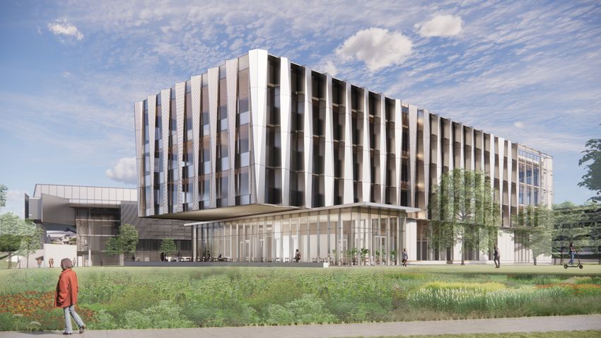

May 17, 2022

Lisa Nicholas, Director of Planning & Development
Department of Planning, Building, Zoning & Economic Development
City of Ithaca
108 East Green Street
Ithaca, NY 14850-5690

Re: Site Plan Review for Cornell University New Computing and Information Science Building

Dear Director Nicholas:

Cornell University is proposing to construct a Computing and Information Science (CIS) building that will create a
dynamic new environment for the growing areas of Computer Science, Information Science, and Statistics and Data
Science. The proposed building will be located adjacent to the south of the Bill and Melinda Gates Hall (Gates Hall), in
the area currently occupied by Hoy Baseball Field. The building is proposed as four-stories tall, approximately 133,000
square feet, and will include a diversity of spaces for students, faculty, and staff. The project site will be redeveloped
to include a new quad along with native landscaping and plaza spaces. The site will also include pedestrian/vehicular
circulation, accessible vehicle parking, electric vehicle parking, and a service drive/court.

Included in this booklet you will find a detailed project narrative and an illustrated site plan. Also included is an 11x17
drawing set. The City’s Development Review Application, Part I of the Full Environmental Assessment Form (FEAF), and
two full-size sets of drawings are also provided. The technical drawing set includes the following:

G0.00 Cover Sheet                          C403 Details                                L1.00 Site Plan
                                           C404 Details                                L1.01 Site Plan
Civil                                      C405 Details                                L1.02 Site Plan
C000 Civil Legend And Notes                                                            L1.03 Site Plan
C100 Survey                                Site Utility                                L2.00 Layout Plan
C101 Existing Topographic Plan             SU1.00 Site Utility Plan                    L2.01 Layout Plan
C102 Existing Topographic Plan             SU2.00 Site Details                         L2.02 Layout Plan
C103 Existing Utility Plan                 G3.00 Fire Apparatus Access Plan            L2.03 Layout Plan
C104 Existing Utility Plan                                                             L2.20 Lighting Layout Plan
C201 Site Demolition Plan                  Landscape                                   L2.21 Lighting Layout Plan
C202 Site Demolition Plan                  L0.01 Illustrative Site Plan                L2.22 Lighting Layout Plan
C203 Site Utility Demolition Plan          L1.00A Site Plan With Existing              L2.23 Lighting Layout Plan
C204 Site Utility Demolition Plan          Topography Background                       L3.00 Materials Plan
C301 Site Utility Plan                     L1.00B Site Plan With Existing              L3.01 Materials Plan
C302 Site Utility Plan                     Survey Background                           L3.02 Materials Plan
C401 Details                               L0.00 Key Plan                              L3.03 Materials Plan
C402 Details                               L0.50 Tree Protection Plan                  L3.50 Paving Plan

                                                                                              Continued on following page
                                  TWM - A Fisher Associates Landscape Architecture Studio
                                           Fisher Associates, P.E., L.S., L.A., D.P.C.
                          1001 West Seneca Street, Suite 201 Ithaca, New York 14850 ph: 607.277.1400
                                              www.twm.la | www.fisherassoc.com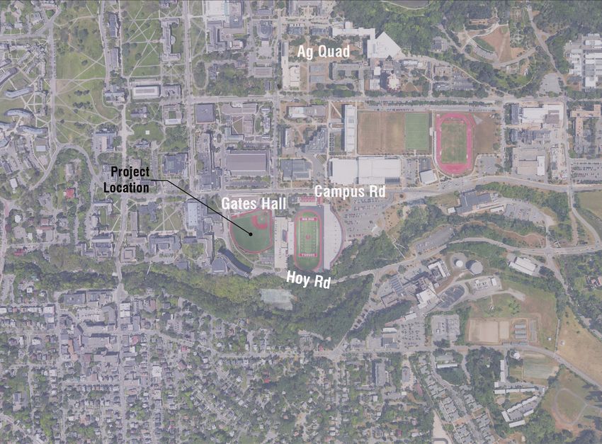
L3.51 Paving Plan - Enlargements         L8.03 Site Details                       A1.03 Third Floor Plan
L4.00 Grading Plan                       L8.04 Site Details                       A1.04 Fourth Floor Plan
L4.01 Grading Plan                       L9.00 Planting Plan                      A1.05 Roof Plan
L4.02 Grading Plan                       L9.01 Planting Plan                      A3.04 Composite Building
L4.03 Grading Plan                       L9.02 Planting Plan                      Elevations
L5.00 Soils Plan                         L9.03 Planting Plan                      A3.05 Composite Building
L5.01 Soils Plan                         L9.10 Planting Details                   Elevations / Campus Road Link
L5.02 Soils Plan                         L9.20 Planting Details
L5.03 Soils Plan                                                                  Photometrics
L7.00 Site Sections                      Architectural                            SE1.00 Site Photometrics Plan
L8.00 Site Details                       A1.00 Basement Plan                      SE1.01 Site Photometrics Plan
L8.01 Site Details                       A1.01 First Floor Plan
L8.02 Site Details                       A1.02 Second Floor Plan

If you have any questions or require further information, please do not hesitate to call. We are looking forward to
presenting the project to the Planning & Development Board on June 28th. At that meeting we are hoping to introduce
the project and have the Board declare its intent to act as Lead Agency pursuant to the State Environmental Quality
Review Act (SEQRA).

Sincerely,

Kimberly Michaels
Director of Landscape Architecture

                                TWM - A Fisher Associates Landscape Architecture Studio
                                         Fisher Associates, P.E., L.S., L.A., D.P.C.
                        1001 West Seneca Street, Suite 201 Ithaca, New York 14850 ph: 607.277.1400
                                            www.twm.la | www.fisherassoc.com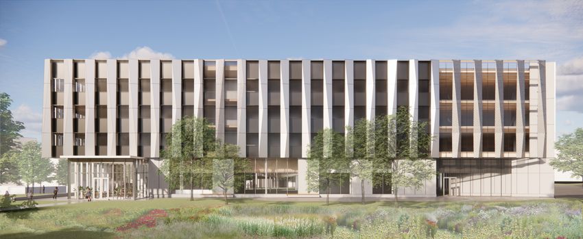
Project Consultants
Leers Weinzapfel Associates
Project Architect

TWM - A Fisher Associates Landscape Architecture Studio
Fisher Associates, P.E., L.S., L.A., D.P.C.
Project Municipal Approvals

The Olin Studio
Project Landscape Architect

T.G. Miller, P.C.
Project Civil Engineer

WB Engineers + Consultant
Accessibility and Code Support

Thornton Tomasetti
Project Structural Engineer

BVH Integrated Services
Project Mechanical, Electrical and Plumbing Engineers, Energy Modeling

John P. Stopen Engineering, LLP
Project Geotechnical Engineer
This page has been intentionally left blank.
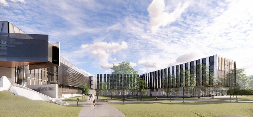
Table of Contents

Site Plan Review Application................................................................................................. 9
Project Narrative................................................................................................................. 13
Full Environmental Assessment Form.................................................................................. 37
Supplemental Information................................................................................................... 51
  Impact on Land................................................................................................................ 52
  Impact on Water............................................................................................................... 52
  Impact on Air................................................................................................................... 52
  Impact on Plants, Animals & Agriculture........................................................................... 53
  Impact on Aesthetic Resources......................................................................................... 53
  Impact on Cultural Resources........................................................................................... 53
  Impact on Open Space & Recreation................................................................................ 53
  Impact on Critical Environmental and Unique Natural Areas............................................... 53
  Impact on Transportation.................................................................................................. 54
  Impact on Energy............................................................................................................. 54
  Impacts from Sound, Odor & Light................................................................................... 54
  Impact on Human Health.................................................................................................. 55
  Impact on Growth & Character of Community................................................................... 55
  Impacts from Construction............................................................................................... 55
                                                                                                             (separate packet)
Technical Drawing Set (11x17)..........................................................................................          111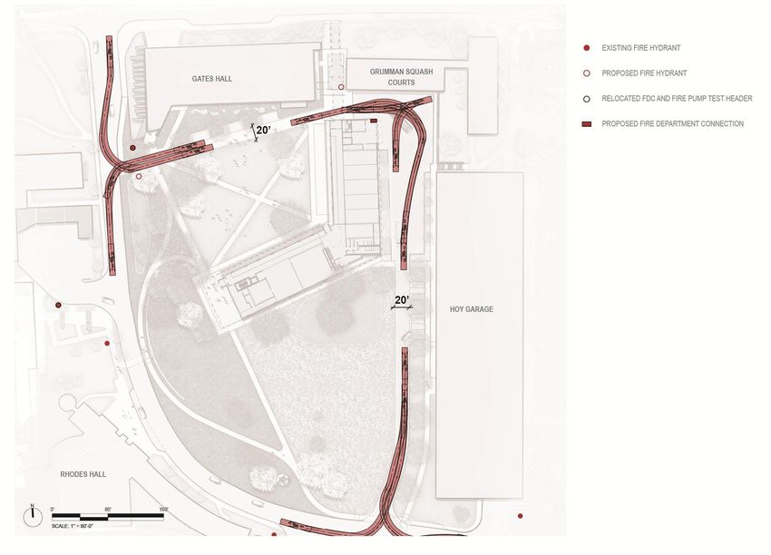
This page has been intentionally left blank.
Site Plan Review Application

                               9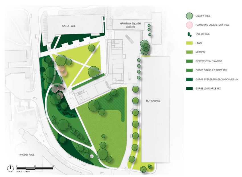
This page has been intentionally left blank.
CONTACT: BUILDING PERMIT NUMBER:
Lisa Nicholas, Deputy Director of Planning
PLANNING DIVISION ____________ (REQUIRED)
108 E. Green St., 3rd Floor
Ithaca, NY 14850 │ (607) 274‐6550
City of Ithaca
lnicholas@cityofithaca.org SITE PLAN REVIEW (SPR) APPLICATION
APPLICANT: Name: Kimberly Michaels Title/Role: Director of Landscape Architecture
Address 1: TWM, a Fisher Associates Landscape Architecture Studio
Address 2: 1001 W. Seneca St. Suite 201 City, State, & Zip Code: Ithaca, NY 14850
Telephone: 607-277-1400 Cell Phone: E‐Mail: Kam@twm.la
CONSULTANT: Name: Leers Weinzapfel Associates Title/Role: Project Architect
Address 1: 75 Kneeland Street
Address 2: City, State, & Zip Code: Boston, MA 02111
Telephone: 617-423-5731 Cell Phone: E‐Mail: wastopps@lwa-architects.com
PROJECT SPONSOR: Name: Patrick Conrad Title/Role: Project Manager
(if other than applicant)
Address 1: Cornell University, Humphreys Service Building
Address 2: 639 Dryden Road City, State, & Zip Code: Ithaca, NY 14850
Telephone: 607-255-1399 Cell Phone: E‐Mail: pcc23@cornell.edu
― PROJECT DESCRIPTION ―
Project Title: Cornell University New Computing and Information Science Building Project Address: Hoy Road
Project Type (check one): Residential Commercial Industrial Institutional Mixed‐Use
Scope of Work (check all that apply & indicate approximate operation/construction cost):
Vegetation Removal $ Façade Change $ Demolition $
New Paving $ Earthwork $ New Plantings $
New Structure $ Structure Expansion $ Accessory Structure $
Tree Removal $ New Parking $ Landscaping $
Addition to Building/Structure $
Total Construction Cost: $ 76 M Anticipated Construction Period: Feb/March '23 to Feb/March 25'
(best estimate) (best estimate)
― OWNER INFORMATION ―
1. If the development site is leased property, list the property owner's name and address below:
N/A
Length of Lease:
Note: If property is not owned by Project Sponsor, OWNER’S AUTHORIZATION FORM required.
1 of 22. Please record the application date and approval status of any required federal, state, and/or local permits or approvals
for this project:
Type Approval Agency Application Date Approval Status
Demolition Building Division
Building Building Division 5-17-2022
5-16-2022
Ithaca Landmarks Preservation Commission (ILPC)
Board of Zoning Appeals (BZA)
Board of Public Works (BPW)
3. Identify any existing restriction(s) relevant to development of this property: None
Other:
Deed Restriction(s) Lien(s) Easement(s) License Agreement(s)
_________________
― APPLICATION FEE ―
Application fee is based on total construction, site work, and landscaping costs, charged in accordance with the following
schedule. The fee is payable by check to the “City of Ithaca,” upon submission of this application.
Type of Approval Project Cost Application Fee
less than $10,000 $75
$10,000 to $49,999 $150
Site Plan Review
$50,000 to $100,000 $300
over $100,000 $1.50 per $1,000
* less than $50,000 $150
Modified Site Plan
Review $50,000 or more $250
* Modified Site Plan Review fee only applies to modifications to approved site plans that do not trigger reconsideration of
Determination of Environmental Significance. Modifications that require additional environmental review should follow fee
schedule for full Site Plan Review. This determination will be made at time of application.
― QUICK APPLICATION CHECKLIST ―
Item No. of Copies
Application Form (completely filled out and signed) 14
Short Environmental Assessment Form (SEAF) (completely filled out and signed) 14
Full Environmental Assessment Form (FEAF) ― Part 1 [if required] (completely filled out and signed) 14
Full‐Size Drawings: (1) scalable site survey with building footprint(s); and (2) height elevations 2
Reduced Drawings (11”x17”) [see “Site Plan Review Application Checklist”] 14
Site Plan Review Application Fee
ELECTRONIC SUBMISSIONS: You must provide electronic versions of ALL submitted documents.
LARGE FILES: Incoming e‐mails to the City must be under 10 MB in size (incl. message envelope), so please either provide a flash/thumb drive, or use a
free file‐sharing web site, like: www.hightail.com, www.dropbox.com, www.google.com/drive, etc. You can also split documents into smaller parts
and send multiple e‐mails/files to: lnicholas@cityofithaca.org or aharris@cityofithaca.org.
Applicant's Signature: Date: 5-17-2022
By signing this application form, the applicant acknowledges City staff may visit the site in order to fully understand the proposed development.
2 of 2Project Narrative
13This page has been intentionally left blank.
Project Narrative

Project Narrative
Project Summary
Cornell University is proposing to construct a Computing and Information Science (CIS) building that will create a dynamic new
environment for the growing areas of Computer Science, Information Science, and Statistics and Data Science. The proposed
building will be located adjacent to the south of the Bill and Melinda Gates Hall (Gates Hall), in the area currently occupied by
Hoy Baseball Field. The building is proposed as four-stories tall, approximately 133,000 square feet, and will include a diversity
of spaces for students, faculty, and staff. The project site will be redeveloped to include new greenspace along with native
landscaping and plaza spaces. The site will also include pedestrian/vehicular circulation, accessible vehicle parking, electric
vehicle parking, and a service drive/court.

Project Purpose, Need & Benefit
Burgeoning student enrollment is driving growth for Cornell Bowers Computing and Information Science (CIS) programs. Vital
to meeting this student demand and maintaining its world leadership is the expansion of the college’s faculty. Collaborative
research is fundamental to Cornell and the Ann S. Bowers College of Computing and Information Science. Its three departments
have a leadership role in several strategic disciplines of the university’s new “Radical Collaboration Drives Discovery” including:

    •    Artificial Intelligence (computational sustainability, ethics and policy, machine learning and robotics)

    •    Quantum Science and Technology (quantum computing and cryptography)

    •    Data Science (computational social science, privacy, security and fairness)

    •    Digital Agriculture to create sustainable agriculture and food systems

    •    Design and Technology to pioneer new advancements in experimental design and technology

         The new building will provide well-equipped academic and research facilities with cutting-edge technologies for
         Bowers CIS faculty and faculty across campus to collaborate on these cross-cutting research initiatives. The facilities
         also expand experiential learning opportunities for our 2,000 undergraduate majors to work with faculty, combining
         classroom and research experience. Examples of experiential learning and student projects benefiting the local
         community include:

    •    Students enrolled in Bowers CIS majors are members of a variety of student groups like CornellAppDev who develop
         tech and apps to assist our community. Recent examples include Ithaca Transit and Snow Angels.

    •    In partnership with the Unbroken Promise Initiative, students in Information Science’s Master of Information Science
         program researched and developed a report outlining the context, needs, and challenges of Ithaca’s West Village
         community.

         Other examples of programs focused on local STEM educational outreach include the Cornell High School
         Programming Contest and the undergraduate Women in Computing at Cornell who coordinate Girls Who Code
         workshops for high school and middle students in the Ithaca area.

         The Cornell Institute for Digital Architecture is helping regional farmers produce food (Programmable plant systems
         grant; create a digital ecosystem that has the computational tools and data analysis approaches that will allow users to
         use this dataset to ask important biological questions) and lower environmental impact; it also helps lower the cost and
         make food more accessible for all.

         Bowers CIS faculty who are recognized experts in their fields have an impact on federal research policy through their
         participation on national advisory boards, including security and artificial intelligence.

                                                                                                                                        15
Project Narrative
Location
The proposed CIS building is located on the Ithaca campus of Cornell University, in the City of Ithaca, on a site that is currently
improved with an artificial turf baseball field, associated facilities, landscaping/lawn, and parking. The site is accessed from
Hoy Road on the south and west. The site is bounded by the Bill and Melinda Gates Hall and Grumman Squash Courts building
on the north along Campus Road, Hoy Road on the west and south, and the Hoy Garage on the east. The project site is at the
southern portion of central campus.
The site of the proposed building is located within the City of Ithaca on a portion of Tax Parcel No 31.-1-1.2, which is
approximately 154 acres in size per the County Assessment tax mapping. This parcel has a “Campus” address, and the limit of
disturbance for the project will be approximately 5.7 acres confined to the area bounded by Hoy Road on the south and west,
Gates Hall on the north, and Hoy Garage on the east.
A small surface parking lot exists at the southern end of the site along Hoy Road. Cascadilla Creek is located across the
street from the site, south of Hoy Road and is confined to a relatively narrow channel, surrounded by steep slopes and dense
vegetation. The primary vehicular and service access for the site is Hoy Road on the west and south. The site is developed, and
its environs have been disturbed areas since the construction of the existing baseball field and support facilities several decades
ago.
The proposed Cornell Bowers Computing and Information Science (CIS) Building will be built to the immediate south of Bill and
Melinda Gates Hall which is located along Campus Roady Road at the corner of Hoy Road. The CIS building will be four stories
tall with an L-shaped configuration. Landscaped greenspace is proposed between the new building and Gates Hall.
Setting
The proposed project site at the southern portion of the campus is in an area that includes Bill and Melinda Gates Hall and
Grumman Squash Courts on the north, large academic buildings to the west, Hoy Garage and Schoelkopf Crescent and parking
areas to the east, and Cascadilla Creek and its associated natural protection zones to the south. The Cascadilla Creek corridor
and Hoy Road separate the campus at this point from residential areas to the south. To the north of Campus Road is the
developed campus, with research and teaching facilities, the central athletic facilities, and several parking areas.
16Project Narrative
Figure 1: Location Map.
17This page has been intentionally left blank.
Project Narrative

     Figure 2: Location Map in context with Cornell.

19
This page has been intentionally left blank.
Project Narrative

Zoning
The proposed building will be located fully within the City of Ithaca U-1 (University) Zoning District. The project is an
allowed use within the University Zone and meets all the regulations of the U-1 Zone.

         U1-Zone
         Within the U-1 zone, there are no requirements related to off-street loading, minimum lot size or lot width at
         the street line. There are also no yard dimension requirements in the code that are applicable to the project.
         Relative to building height, there are no limits to the number of stories, and building height is generally
         limited to 175 feet. The proposed building will be shorter than this limit, with the top of the roof structure at
         64 feet above grade and the top of elevator penthouse at 77 feet above grade.

         The project site is included tax parcel 31.-1-1.2, which captures most of central campus, approximately 80
         buildings and is 154 acres in total size. 35% lot coverage is permitted in this zone, allowing for 53.9 acres of
         development. Existing structures on this parcel amass to 31.6 acres. This project will add approximately half
         an acre of development to the tax parcel, which is well within the total lot coverage allowance.

         Gorge Protection Zone & Unique Natural Area
         The project is outside the proximate Gorge Protection Area (GP-A); the limit of GP-A limit is along the south
         edge of Hoy Road, which is across the street from the project. In addition, the project is fully outside the
         Cascadilla Unique Natural Area. The limit for this UNA is also the south edge of Hoy Road, across the street
         from the project.

         Tompkins County GML 239 Review
         The proposed project will likely require 239 Review based on geographic location triggers for being within
         500 feet of the following:
               “The boundary of any existing or proposed county or state park or any other recreation area”
               “The existing or proposed right-of-way of any stream or drainage channel owned by the county or for
               which the county has established channel line”

                                                                                                                                          21
Project Narrative
Building Program
The proposed new building for the Cornell Bowers College for Computing and Information Science will be linked to
the existing (Gates Hall) at 107 Hoy Road, the current home of Bowers CIS. The space between these two buildings
will create a new open green space that will provide a visual link across Hoy Road to Rhodes and Upson Halls,
buildings that also house elements of Bowers CIS. The proposed building will be four stories high, with a footprint
of approximately 28,500 square feet, and contain approximately 133,000 square feet of space including a large
mechanical basement. The ground floor of the proposed building will contain the most active elements of the building,
including a café adjacent to the entrance, a generous Commons for gathering, two classrooms and spaces for maker
and builder labs. The upper floors contain quiet research and administrative offices, research computational spaces,
instructional spaces, meeting spaces, common/multi-purpose spaces, and offices for faculty and staff. A three-story
enclosed bridge will connect the proposed new building to the east end of Gates Hall on the second through
fourth floors. The connection between the proposed building and Gates Hall includes a pedestrian entrance facing
Campus Road.
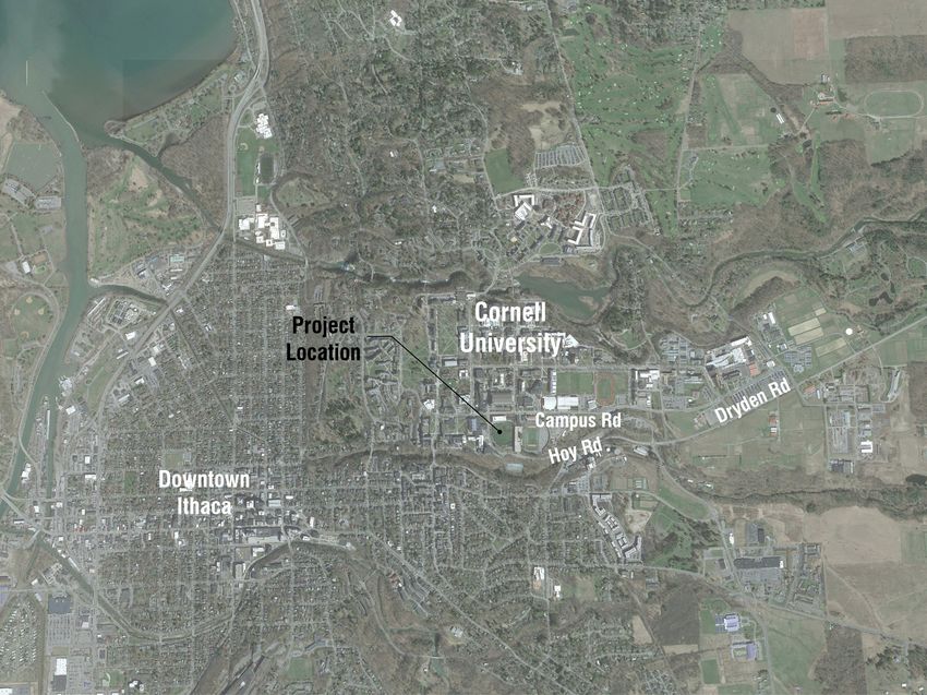
Architectural Design
The proposed new building consists of two four-story wings forming an open angle “L” which frames a shared
greenspace with Gates Hall. The new building will be fully accessible along its length, with multiple entrances. The
main entrance will face Hoy Road, reached by a sloping accessible path.
The ground floor is predominantly windows, with an exterior sheltered arcade and interior gallery surrounding the
proposed greenspace. A terrace at the Hoy Road entrance will provide exterior, covered seating for an interior café.
A predominantly metal panel envelope is proposed for the upper floors of the proposed building. Windows and
sunshades for offices and computational labs will be interwoven with vertical metal accent panels on the upper three
floors. The surrounding campus buildings have diverse façade materials, including concrete, brick, terra cotta and metal
panel. Gates Hall, (which is closest to and joins at three levels to the proposed building), is wrapped in a silvery metal
screen over a glazed curtainwall façade.
22Figure 3: Schematic Rendering, view looking east from Hoy Road.
23This page has been intentionally left blank. 24
Figure 4: Schematic Rendering, southwest corner of building.

                                                               25
This page has been intentionally left blank. 26
Figure 5: Schematic Rendering, south façade.

                                               27
This page has been intentionally left blank. 28
Project Narrative
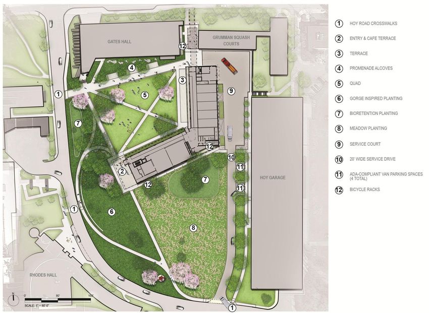
Site Development
The proposed building will be located adjacent and south of Gates Hall, in the area currently occupied by Hoy Baseball
Field. The project site will be redeveloped in service of the new building, with proposed site improvements include
pedestrian paths/sidewalks, an open lawn green, paved gathering/event spaces, and direct connections to Gates Hall,
Hoy Garage, and Hoy Road.
The overall site is gradually sloped which will facilitate programming within the green and new plantings. The
western edge of the site, along Hoy Road, will be planted with native species. Two bioretention zones will manage
site stormwater. To the south, the proposed building will overlook meadow plantings. Along the eastern edge of the
site, a row of trees will buffer views of Hoy Garage. Multiple pedestrian walkways provide interior site circulation and
connections to the greater campus. A service driveway a the south end of site leads to a service court.
DRAWING LIST - VOLUME 1
GENERAL ARCHITECTURAL
DEMOLITION A5.09A FOURTH FLOOR NORTH WING FINISH PLAN S3.23 SHEAR WALL ELEVATIONS III
G0.00A COVER SHEET - VOLUME 1 A1.00
D1.00 BASEMENT PLAN PLANS
GATES DEMOLITION A5.09B FOURTH FLOOR SOUTH WING FINISH PLAN S3.31 TYPICAL SHEAR WALL DETAILS I
G0.01A DRAWING LIST - VOLUME 1 A1.01 FIRST FLOOR PLAN A5.10 PARTITION TYPES - GWB S3.32 TYPICAL SHEAR WALL DETAILS II
G0.01B DRAWING LIST - VOLUME 2 A1.02 SECOND FLOOR PLAN A5.11 PARTITION TYPES - GWB S3.33 TYPICAL SHEAR WALL DETAILS III
G0.02 GENERAL NOTES & ANNOTATION LEGEND A1.03 THIRD FLOOR PLAN A5.12 PARTITION TYPES - CMU S4.01 TYPICAL CONCRETE COLUMN DETAILS
CIVIL A5.30 DOOR/FRAME TYPES S4.02 CONCRETE COLUMN SCHEDULE
G0.03
C100 ALTERNATES
SURVEY A1.04 FOURTH FLOOR PLAN
C000 CIVIL LEGEND AND NOTES A6.00 MOUNTING HEIGHT LEGEND S4.03 TYPICAL CONCRETE SLAB DETAILS I
G1.00 CODE SUMMARY A1.05 ROOF PLAN
C101 EXISTING TOPOGRAPHIC PLAN A6.40 INTERIOR ELEVATIONS - FIRST FLOOR S4.04 TYPICAL CONCRETE SLAB DETAILS II
G1.01 CODE SUMMARY A1.05ALT PHOTO-VOLTAIC ALTERNATES
C102 EXISTING TOPOGRAPHIC PLAN A6.41 INTERIOR ELEVATIONS - CROSSROADS S4.05 TYPICAL CONCRETE TWO WAY SLAB DETAILS I
G1.02 CODE SUMMARY
C103 EXISTING UTILITY PLAN A6.42 INTERIOR ELEVATIONS - NORTH WING CORRIDOR FLOORS 2 - 4 S4.06 TYPICAL CONCRETE TWO WAY SLAB DETAILS II
G2.00 LIFE SAFETY PLAN BASEMENT
C104 EXISTING UTILITY PLAN A6.43 INTERIOR ELEVATIONS - SOUTH WING CORRIDOR FLOORS 2 - 4 S5.01 TYPICAL STEEL COLUMN DETAILS I
G2.01 LIFE SAFETY PLAN FIRST FLOOR
C201 SITE DEMOLITION PLAN A7.00 NORTH STAIR 2 PLANS & SECTIONS S5.02 TYPICAL STEEL COLUMN DETAILS II
G2.02 LIFE SAFETY PLAN SECOND FLOOR
C202 SITE DEMOLITION PLAN A7.01 SOUTH STAIR 1 PLANS & SECTIONS S5.03 TYPICAL STEEL COLUMN DETAILS III
G2.03 LIFE SAFETY PLAN THIRD FLOOR
C203 SITE UTILITY DEMOLITION PLAN A7.02 CROSSROADS STAIRS 3 & 4 PLANS & SECTIONS S5.04 TYPICAL STEEL BEAM DETAILS I
G2.04 LIFE SAFETY PLAN FOURTH FLOOR
C204 SITE UTILITY DEMOLITION PLAN A7.10 STAIR DETAILS S5.05 TYPICAL STEEL BEAM DETAILS II
G2.05 LIFE SAFETY PLAN ROOF
C301 SITE UTILITY PLAN A8.00 FOUNDATION DETAILS S5.06 TYPICAL STEEL BEAM DETAILS III
C302 SITE UTILITY PLAN A8.01 EXTERIOR WALL SECTION DETAILS S5.07 TYPICAL STEEL BEAM DETAILS IV
C401 DETAILS S A8.02 EXTERIOR WALL SECTION DETAILS S5.08 TYPICAL STEEL BEAM DETAILS V
C402 DETAILS A1.10 BASEMENT ENLARGED PLAN A8.03 EXTERIOR WALL SECTION DETAILS S5.09 TYPICAL STEEL BEAM DETAILS VI
C403 DETAILS A1.11A FIRST FLOOR NORTH WING ENLARGED PLAN A8.04 EXTERIOR WALL SECTION DETAILS S5.10 TYPICAL STEEL BEAM PENETRATION DETAILS I
C404 DETAILS A1.11B FIRST FLOOR SOUTH WING ENLARGED PLAN A8.05 EXTERIOR WALL SECTION DETAILS S5.11 TYPICAL STEEL BEAM PENETRATION DETAILS II
C405 DETAILS A1.12A SECOND FLOOR NORTH WING ENLARGED PLAN A8.06 EXTERIOR WALL SECTION DETAILS S5.12 TYPICAL COMPOSITE STEEL DECK DETAILS I
A1.12B SECOND FLOOR SOUTH WING ENLARGED PLAN A8.11 EXTERIOR WALL PLAN DETAILS S5.13 TYPICAL COMPOSITE STEEL DECK DETAILS II
SITE UTILITY A1.13A THIRD FLOOR NORTH WING ENLARGED PLAN A9.00 INTERIOR GLAZING TYPES - FIRST FLOOR S5.14 TYPICAL COMPOSITE STEEL DECK DETAILS III
SU1.00 SITE UTILITY PLAN A1.13B THIRD FLOOR SOUTH WING ENLARGED PLAN A9.01 INTERIOR GLAZING TYPES - VESTIBULES AND SECOND FLOOR S5.15 TYPICAL COMPOSITE STEEL DECK DETAILS IV
SU2.00 SITE DETAILS A1.14A FOURTH FLOOR NORTH WING ENLARGED PLAN NORTH WING S5.16 TYPICAL COMPOSITE STEEL DECK DETAILS V
A1.14B FOURTH FLOOR SOUTH WING ENLARGED PLAN A9.02 INTERIOR GLAZING TYPES - SECOND FLOOR S5.17 TYPICAL COMPOSITE STEEL DECK DETAILS VI
A1.15A ROOF NORTH WING ENLARGED PLAN A9.03 INTERIOR GLAZING TYPES - 2ND TO 4TH FLOOR S5.20 STEEL COLUMN SCHEDULE I
LANDSCAPE A1.15B ROOF SOUTH WING ENLARGED PLAN A9.04 INTERIOR GLAZING TYPES - FOURTH FLOOR AND LINK S5.21 STEEL COLUMN SCHEDULE II
L0.00 KEY PLAN A1.16 LINK ENLARGED PLANS A9.05 CEILING MILLWORK - FIRST FLOOR S5.22 STEEL COLUMN SCHEDULE III
L0.01 ILLUSTRATIVE SITE PLAN
A2.00 BASEMENT REFLECTED CEILING PLAN A9.06 CEILING MILLWORK - FIRST FLOOR S5.23 STEEL COLUMN SCHEDULE IV
L0.02 FIRE ACCESS PLAN
L0.50 TREE PROTECTION PLAN A2.01A FIRST FLOOR NORTH WING REFLECTED CEILING PLAN S5.50ALT TYPICAL CLT DETAILS - ALTERNATE S1
L1.00A
L100A SITE PLAN -WITH EXISTING
EXISTING TOPOGRAPHY BACKGROUND
CONTOURS A2.01B FIRST FLOOR SOUTH WING REFLECTED CEILING PLAN VERTICAL TRANSPORTATION
L1.00B
L100B SITE PLAN -WITH EXISTING
EXISTING SURVEY BACKGROUND
LINEWORK A2.02A SECOND FLOOR NORTH WING REFLECTED CEILING PLAN VT.01 ELEVATOR 1 PLANS & SECTION
L1.00 SITE PLAN A2.02B SECOND FLOOR SOUTH WING REFLECTED CEILING PLAN VT.02 ELEVATOR 2 PLANS & SECTION
L1.01 SITE PLAN A2.03A THIRD FLOOR NORTH WING REFLECTED CEILING PLAN
L1.02 SITE PLAN A2.03B THIRD FLOOR SOUTH WING REFLECTED CEILING PLAN
L1.03 SITE PLAN A2.04A FOURTH FLOOR NORTH WING REFLECTED CEILING PLAN STRUCTURAL
L2.00 LAYOUT PLAN A2.04B FOURTH FLOOR SOUTH WING REFLECTED CEILING PLAN S0.00 COVER SHEET
L2.01 LAYOUT PLAN A2.05 LINK AND PENTHOUSE REFLECTED CEILING PLANS S0.01 GENERAL NOTES I
L2.02 LAYOUT PLAN A3.00 PERSPECTIVES S0.02 GENERAL NOTES II
L2.03 LAYOUT PLAN A3.01 NORTH EXTERIOR AXONOMETRIC VIEW S0.03 GENERAL NOTES III
L2.20 LIGHTING LAYOUT PLAN A3.02 WEST / EAST EXTERIOR AXONOMETRIC VIEWS S0.04 LOADING DIAGRAMS I
L2.21 LIGHTING LAYOUT PLAN A3.03 SOUTH EXTERIOR AXONOMETRIC VIEW S0.05 LOADING DIAGRAMS II
L2.22 LIGHTING LAYOUT PLAN A3.04 COMPOSITE BUILDING ELEVATIONS S0.06 LOADING DIAGRAMS III
L2.23 LIGHTING LAYOUT PLAN A3.05 COMPOSITE BUILDING ELEVATIONS / CAMPUS ROAD LINK S0.10 LAP SPLICE SCHEDULE I
L3.00 MATERIALS PLAN A3.06 COMPOSITE BUILDING ELEVATIONS MATERIAL CALCULATION S0.11 LAP SPLICE SCHEDULE II
L3.01 MATERIALS PLAN A3.07 COMPOSITE BUILDING ELEVATIONS MATERIAL CALCULATION / S1.10 BASEMENT FOUNDATION PLAN
L3.02 MATERIALS PLAN CAMPUS ROAD LINK S1.11 FIRST LEVEL FRAMING AND FOUNDATION PLAN
L3.03 MATERIALS PLAN A3.10 CURTAIN WALL TYPE A, B & C S1.12 SECOND LEVEL FRAMING PLAN
L3.50 PAVING PLAN A3.11 CURTAIN WALL TYPE D, E & F S1.12ALT SECOND LEVEL FRAMING PLAN - ALTERNATE S1
L3.51 PAVING PLAN - ENLARGEMENTS A3.12 CURTAIN WALL TYPE G, H, I & J S1.13 THIRD LEVEL FRAMING PLAN
L4.00 GRADING PLAN A3.13 CURTAIN WALL TYPE K S1.13ALT THIRD LEVEL FRAMING PLAN - ALTERNATE S1
L4.01 GRADING PLAN A3.14 CURTAIN WALL TYPE L S1.14 FOURTH LEVEL FRAMING PLAN
L4.02 GRADING PLAN A3.15 CURTAIN WALL TYPE M, N & O S1.14ALT FOURTH LEVEL FRAMING PLAN - ALTERNATE S1
L4.03 GRADING PLAN A3.16 CURTAIN WALL TYPE P & Q S1.15 ROOF FRAMING PLAN
L5.00 SOILS PLAN A3.17 CURTAIN WALL TYPE R, S & T S1.15ALT ROOF FRAMING PLAN - ALTERNATE S1
L5.01 SOILS PLAN A3.20 WINDOW TYPES S1.16 PENTHOUSE ROOF FRAMING PLAN
L5.02 SOILS PLAN A3.30 EXTERIOR DOOR TYPES S2.10 TYPICAL CAISSON DETAILS I
L5.03 SOILS PLAN A3.40 LOUVER TYPES S2.11 TYPICAL SLAB ON GRADE DETAILS I
L7.00 SITE SECTIONS A4.00 BUILDING LONGITUDINAL SECTIONS S2.12 TYPICAL SLAB ON GRADE DETAILS II
L8.00 SITE DETAILS A4.01 BUILDING PERPENDICULAR SECTIONS S2.13 TYPICAL STRUCTURAL SLAB ON GRADE DETAILS
L8.01 SITE DETAILS A4.02 LINK SECTIONS S2.14 TYPICAL FOUNDATION WALL DETAILS I
L8.02 SITE DETAILS A4.10 TYPICAL EXTERIOR ENVELOPE ASSEMBLIES S2.15 TYPICAL FOUNDATION WALL DETAILS II
L8.03 SITE DETAILS A4.20 EXTERIOR WALL SECTIONS AND ENLARGED ELEVATIONS S2.16 TYPICAL GRADE BEAM DETAILS I
L8.04 SITE DETAILS A4.21 EXTERIOR WALL SECTIONS AND ENLARGED ELEVATIONS S2.17 TYPICAL GRADE BEAM DETAILS II
L9.00 PLANTING PLAN A4.22 EXTERIOR WALL SECTIONS AND ENLARGED ELEVATIONS S2.18 TYPICAL GRADE BEAM DETAILS III
L9.01 PLANTING PLAN A4.23 EXTERIOR WALL SECTIONS AND ENLARGED ELEVATIONS S2.19 TYPICAL MAT FOUNDATION DETAILS
L9.02 PLANTING PLAN A4.24 EXTERIOR WALL SECTIONS AND ENLARGED ELEVATIONS S3.01 BRACED FRAME ELEVATIONS
L9.03 PLANTING PLAN A5.05A BASEMENT FLOOR NORTH WING FINISH PLAN S3.02 VIERENDEEL TRUSS ELEVATIONS I
L9.10 PLANTING SCHEDULE A5.06A FIRST FLOOR NORTH WING FINISH PLAN S3.03 VIERENDEEL TRUSS ELEVATIONS II
L9.20 PLANTING DETAILS A5.06B FIRST FLOOR SOUTH WING FINISH PLAN S3.11 TYPICAL BRACE FRAME CONNECTION DETAILS I
A5.07A SECOND FLOOR NORTH WING FINISH PLAN S3.12 TYPICAL BRACE FRAME CONNECTION DETAILS II
A5.07B SECOND FLOOR SOUTH WING FINISH PLAN S3.13 TYPICAL BRACE FRAME BASE CONNECTION DETAILS
A5.08A THIRD FLOOR NORTH WING FINISH PLAN S3.21 SHEAR WALL ELEVATIONS I
A5.08B THIRD FLOOR SOUTH WING FINISH PLAN S3.22 SHEAR WALL ELEVATIONS II
Figure 6. Illustrative Site Plan.
29Project Narrative
Fire/Emergency Access
Fire department apparatus can access the building and site from either a 20’ wide heavy-duty pathway from Hoy
Road to the west or from the 20’ service drive from the south along Hoy Garage. The fire access route allows access
to existing and proposed hydrants and connections as well as access to the north façade of the proposed building
DRAWING LIST - VOLUME 1
and the south façade of Gates Hall.
GENERAL ARCHITECTURAL
DEMOLITION A5.09A FOURTH FLOOR NORTH WING FINISH PLAN S3.23 SHEAR WALL ELEVATIONS III
G0.00A COVER SHEET - VOLUME 1 A1.00
D1.00 BASEMENT PLAN PLANS
GATES DEMOLITION A5.09B FOURTH FLOOR SOUTH WING FINISH PLAN S3.31 TYPICAL SHEAR WALL DETAILS I
G0.01A DRAWING LIST - VOLUME 1 A1.01 FIRST FLOOR PLAN A5.10 PARTITION TYPES - GWB S3.32 TYPICAL SHEAR WALL DETAILS II
G0.01B DRAWING LIST - VOLUME 2 A1.02 SECOND FLOOR PLAN A5.11 PARTITION TYPES - GWB S3.33 TYPICAL SHEAR WALL DETAILS III
G0.02 GENERAL NOTES & ANNOTATION LEGEND A1.03 THIRD FLOOR PLAN A5.12 PARTITION TYPES - CMU S4.01 TYPICAL CONCRETE COLUMN DETAILS
CIVIL A5.30 DOOR/FRAME TYPES S4.02 CONCRETE COLUMN SCHEDULE
G0.03
C100 ALTERNATES
SURVEY A1.04 FOURTH FLOOR PLAN
C000 CIVIL LEGEND AND NOTES A6.00 MOUNTING HEIGHT LEGEND S4.03 TYPICAL CONCRETE SLAB DETAILS I
G1.00 CODE SUMMARY A1.05 ROOF PLAN
C101 EXISTING TOPOGRAPHIC PLAN A6.40 INTERIOR ELEVATIONS - FIRST FLOOR S4.04 TYPICAL CONCRETE SLAB DETAILS II
G1.01 CODE SUMMARY A1.05ALT PHOTO-VOLTAIC ALTERNATES
C102 EXISTING TOPOGRAPHIC PLAN A6.41 INTERIOR ELEVATIONS - CROSSROADS S4.05 TYPICAL CONCRETE TWO WAY SLAB DETAILS I
G1.02 CODE SUMMARY
C103 EXISTING UTILITY PLAN A6.42 INTERIOR ELEVATIONS - NORTH WING CORRIDOR FLOORS 2 - 4 S4.06 TYPICAL CONCRETE TWO WAY SLAB DETAILS II
G2.00 LIFE SAFETY PLAN BASEMENT
C104 EXISTING UTILITY PLAN A6.43 INTERIOR ELEVATIONS - SOUTH WING CORRIDOR FLOORS 2 - 4 S5.01 TYPICAL STEEL COLUMN DETAILS I
G2.01 LIFE SAFETY PLAN FIRST FLOOR
C201 SITE DEMOLITION PLAN A7.00 NORTH STAIR 2 PLANS & SECTIONS S5.02 TYPICAL STEEL COLUMN DETAILS II
G2.02 LIFE SAFETY PLAN SECOND FLOOR
C202 SITE DEMOLITION PLAN A7.01 SOUTH STAIR 1 PLANS & SECTIONS S5.03 TYPICAL STEEL COLUMN DETAILS III
G2.03 LIFE SAFETY PLAN THIRD FLOOR
C203 SITE UTILITY DEMOLITION PLAN A7.02 CROSSROADS STAIRS 3 & 4 PLANS & SECTIONS S5.04 TYPICAL STEEL BEAM DETAILS I
G2.04 LIFE SAFETY PLAN FOURTH FLOOR
C204 SITE UTILITY DEMOLITION PLAN A7.10 STAIR DETAILS S5.05 TYPICAL STEEL BEAM DETAILS II
G2.05 LIFE SAFETY PLAN ROOF
C301 SITE UTILITY PLAN A8.00 FOUNDATION DETAILS S5.06 TYPICAL STEEL BEAM DETAILS III
C302 SITE UTILITY PLAN A8.01 EXTERIOR WALL SECTION DETAILS S5.07 TYPICAL STEEL BEAM DETAILS IV
C401 DETAILS S A8.02 EXTERIOR WALL SECTION DETAILS S5.08 TYPICAL STEEL BEAM DETAILS V
C402 DETAILS A1.10 BASEMENT ENLARGED PLAN A8.03 EXTERIOR WALL SECTION DETAILS S5.09 TYPICAL STEEL BEAM DETAILS VI
C403 DETAILS A1.11A FIRST FLOOR NORTH WING ENLARGED PLAN A8.04 EXTERIOR WALL SECTION DETAILS S5.10 TYPICAL STEEL BEAM PENETRATION DETAILS I
C404 DETAILS A1.11B FIRST FLOOR SOUTH WING ENLARGED PLAN A8.05 EXTERIOR WALL SECTION DETAILS S5.11 TYPICAL STEEL BEAM PENETRATION DETAILS II
C405 DETAILS A1.12A SECOND FLOOR NORTH WING ENLARGED PLAN A8.06 EXTERIOR WALL SECTION DETAILS S5.12 TYPICAL COMPOSITE STEEL DECK DETAILS I
A1.12B SECOND FLOOR SOUTH WING ENLARGED PLAN A8.11 EXTERIOR WALL PLAN DETAILS S5.13 TYPICAL COMPOSITE STEEL DECK DETAILS II
SITE UTILITY A1.13A THIRD FLOOR NORTH WING ENLARGED PLAN A9.00 INTERIOR GLAZING TYPES - FIRST FLOOR S5.14 TYPICAL COMPOSITE STEEL DECK DETAILS III
SU1.00 SITE UTILITY PLAN A1.13B THIRD FLOOR SOUTH WING ENLARGED PLAN A9.01 INTERIOR GLAZING TYPES - VESTIBULES AND SECOND FLOOR S5.15 TYPICAL COMPOSITE STEEL DECK DETAILS IV
SU2.00 SITE DETAILS A1.14A FOURTH FLOOR NORTH WING ENLARGED PLAN NORTH WING S5.16 TYPICAL COMPOSITE STEEL DECK DETAILS V
A1.14B FOURTH FLOOR SOUTH WING ENLARGED PLAN A9.02 INTERIOR GLAZING TYPES - SECOND FLOOR S5.17 TYPICAL COMPOSITE STEEL DECK DETAILS VI
A1.15A ROOF NORTH WING ENLARGED PLAN A9.03 INTERIOR GLAZING TYPES - 2ND TO 4TH FLOOR S5.20 STEEL COLUMN SCHEDULE I
LANDSCAPE A1.15B ROOF SOUTH WING ENLARGED PLAN A9.04 INTERIOR GLAZING TYPES - FOURTH FLOOR AND LINK S5.21 STEEL COLUMN SCHEDULE II
L0.00 KEY PLAN A1.16 LINK ENLARGED PLANS A9.05 CEILING MILLWORK - FIRST FLOOR S5.22 STEEL COLUMN SCHEDULE III
L0.01 ILLUSTRATIVE SITE PLAN
A2.00 BASEMENT REFLECTED CEILING PLAN A9.06 CEILING MILLWORK - FIRST FLOOR S5.23 STEEL COLUMN SCHEDULE IV
L0.02 FIRE ACCESS PLAN
L0.50 TREE PROTECTION PLAN A2.01A FIRST FLOOR NORTH WING REFLECTED CEILING PLAN S5.50ALT TYPICAL CLT DETAILS - ALTERNATE S1
L1.00A
L100A SITE PLAN -WITH EXISTING
EXISTING TOPOGRAPHY BACKGROUND
CONTOURS A2.01B FIRST FLOOR SOUTH WING REFLECTED CEILING PLAN VERTICAL TRANSPORTATION
L1.00B
L100B SITE PLAN -WITH EXISTING
EXISTING SURVEY BACKGROUND
LINEWORK A2.02A SECOND FLOOR NORTH WING REFLECTED CEILING PLAN VT.01 ELEVATOR 1 PLANS & SECTION
L1.00 SITE PLAN A2.02B SECOND FLOOR SOUTH WING REFLECTED CEILING PLAN VT.02 ELEVATOR 2 PLANS & SECTION
L1.01 SITE PLAN A2.03A THIRD FLOOR NORTH WING REFLECTED CEILING PLAN
L1.02 SITE PLAN A2.03B THIRD FLOOR SOUTH WING REFLECTED CEILING PLAN
L1.03 SITE PLAN A2.04A FOURTH FLOOR NORTH WING REFLECTED CEILING PLAN STRUCTURAL
L2.00 LAYOUT PLAN A2.04B FOURTH FLOOR SOUTH WING REFLECTED CEILING PLAN S0.00 COVER SHEET
L2.01 LAYOUT PLAN A2.05 LINK AND PENTHOUSE REFLECTED CEILING PLANS S0.01 GENERAL NOTES I
L2.02 LAYOUT PLAN A3.00 PERSPECTIVES S0.02 GENERAL NOTES II
L2.03 LAYOUT PLAN A3.01 NORTH EXTERIOR AXONOMETRIC VIEW S0.03 GENERAL NOTES III
L2.20 LIGHTING LAYOUT PLAN A3.02 WEST / EAST EXTERIOR AXONOMETRIC VIEWS S0.04 LOADING DIAGRAMS I
L2.21 LIGHTING LAYOUT PLAN A3.03 SOUTH EXTERIOR AXONOMETRIC VIEW S0.05 LOADING DIAGRAMS II
L2.22 LIGHTING LAYOUT PLAN A3.04 COMPOSITE BUILDING ELEVATIONS S0.06 LOADING DIAGRAMS III
L2.23 LIGHTING LAYOUT PLAN A3.05 COMPOSITE BUILDING ELEVATIONS / CAMPUS ROAD LINK S0.10 LAP SPLICE SCHEDULE I
L3.00 MATERIALS PLAN A3.06 COMPOSITE BUILDING ELEVATIONS MATERIAL CALCULATION S0.11 LAP SPLICE SCHEDULE II
L3.01 MATERIALS PLAN A3.07 COMPOSITE BUILDING ELEVATIONS MATERIAL CALCULATION / S1.10 BASEMENT FOUNDATION PLAN
L3.02 MATERIALS PLAN CAMPUS ROAD LINK S1.11 FIRST LEVEL FRAMING AND FOUNDATION PLAN
L3.03 MATERIALS PLAN A3.10 CURTAIN WALL TYPE A, B & C S1.12 SECOND LEVEL FRAMING PLAN
L3.50 PAVING PLAN A3.11 CURTAIN WALL TYPE D, E & F S1.12ALT SECOND LEVEL FRAMING PLAN - ALTERNATE S1
L3.51 PAVING PLAN - ENLARGEMENTS A3.12 CURTAIN WALL TYPE G, H, I & J S1.13 THIRD LEVEL FRAMING PLAN
L4.00 GRADING PLAN A3.13 CURTAIN WALL TYPE K S1.13ALT THIRD LEVEL FRAMING PLAN - ALTERNATE S1
L4.01 GRADING PLAN A3.14 CURTAIN WALL TYPE L S1.14 FOURTH LEVEL FRAMING PLAN
L4.02 GRADING PLAN A3.15 CURTAIN WALL TYPE M, N & O S1.14ALT FOURTH LEVEL FRAMING PLAN - ALTERNATE S1
L4.03 GRADING PLAN A3.16 CURTAIN WALL TYPE P & Q S1.15 ROOF FRAMING PLAN
L5.00 SOILS PLAN A3.17 CURTAIN WALL TYPE R, S & T S1.15ALT ROOF FRAMING PLAN - ALTERNATE S1
L5.01 SOILS PLAN A3.20 WINDOW TYPES S1.16 PENTHOUSE ROOF FRAMING PLAN
L5.02 SOILS PLAN A3.30 EXTERIOR DOOR TYPES S2.10 TYPICAL CAISSON DETAILS I
L5.03 SOILS PLAN A3.40 LOUVER TYPES S2.11 TYPICAL SLAB ON GRADE DETAILS I
L7.00 SITE SECTIONS A4.00 BUILDING LONGITUDINAL SECTIONS S2.12 TYPICAL SLAB ON GRADE DETAILS II
L8.00 SITE DETAILS A4.01 BUILDING PERPENDICULAR SECTIONS S2.13 TYPICAL STRUCTURAL SLAB ON GRADE DETAILS
L8.01 SITE DETAILS A4.02 LINK SECTIONS S2.14 TYPICAL FOUNDATION WALL DETAILS I
L8.02 SITE DETAILS A4.10 TYPICAL EXTERIOR ENVELOPE ASSEMBLIES S2.15 TYPICAL FOUNDATION WALL DETAILS II
L8.03 SITE DETAILS A4.20 EXTERIOR WALL SECTIONS AND ENLARGED ELEVATIONS S2.16 TYPICAL GRADE BEAM DETAILS I
L8.04 SITE DETAILS A4.21 EXTERIOR WALL SECTIONS AND ENLARGED ELEVATIONS S2.17 TYPICAL GRADE BEAM DETAILS II
L9.00 PLANTING PLAN A4.22 EXTERIOR WALL SECTIONS AND ENLARGED ELEVATIONS S2.18 TYPICAL GRADE BEAM DETAILS III
L9.01 PLANTING PLAN A4.23 EXTERIOR WALL SECTIONS AND ENLARGED ELEVATIONS S2.19 TYPICAL MAT FOUNDATION DETAILS
L9.02 PLANTING PLAN A4.24 EXTERIOR WALL SECTIONS AND ENLARGED ELEVATIONS S3.01 BRACED FRAME ELEVATIONS
L9.03 PLANTING PLAN A5.05A BASEMENT FLOOR NORTH WING FINISH PLAN S3.02 VIERENDEEL TRUSS ELEVATIONS I
L9.10 PLANTING SCHEDULE A5.06A FIRST FLOOR NORTH WING FINISH PLAN S3.03 VIERENDEEL TRUSS ELEVATIONS II
L9.20 PLANTING DETAILS A5.06B FIRST FLOOR SOUTH WING FINISH PLAN S3.11 TYPICAL BRACE FRAME CONNECTION DETAILS I
A5.07A SECOND FLOOR NORTH WING FINISH PLAN S3.12 TYPICAL BRACE FRAME CONNECTION DETAILS II
A5.07B SECOND FLOOR SOUTH WING FINISH PLAN S3.13 TYPICAL BRACE FRAME BASE CONNECTION DETAILS
A5.08A THIRD FLOOR NORTH WING FINISH PLAN S3.21 SHEAR WALL ELEVATIONS I
A5.08B THIRD FLOOR SOUTH WING FINISH PLAN S3.22 SHEAR WALL ELEVATIONS II
Figure 7. Fire Access Plan.
Service Access
A 20’ wide service drive from Hoy Road connects to a service court at the northeast corner of the site. The court
provides sufficient turning space to accommodate garbage trucks, delivery box trucks, and snow removal plows.
The service court includes a loading area at the northwest corner of the building and will also include a trash and
recycling dumpster. Snow removal plows will be able to clear this area, piling snow in both a northern location,
along the south façade of the Grumman Squash Courts, and a southern location, adjacent to the proposed
bioretention area.
30Project Narrative
Landscape
The existing site consists of a sizable artificial turf ballfield with accessory hardscape pathways and plazas; the total area
of existing landscape space is approximately 71,500 square feet. The total proposed landscaped area is approximately
148,500 square feet, nearly doubling the amount of landscaped space on the site.
Forty-six (46) trees currently exist within the project limit of work. In order to facilitate the construction of the Bowers
CIS Building and adjacent fully accessible path network, the removal of thirty-three (33) trees is required. Eight (8)
trees with a diameter at breast height (DBH) larger than 8” are slated for removal. Of these eight trees, two (2) are of
substantial size and aesthetic value - two 16” DBH Salix nigra (Black Willow) located at the northeast corner of the
project site, north of the Hoy Garage. The recommendation for the removal of these trees is based on the review of a
Certified Arborist. The Black Willows have limited space for both crown expansion and additional root growth, and a
high likelihood of future failure and instability due to suboptimal scaffold branch structure.
The proposed landscape design is defined by four planting typologies - lawn, bioretention, meadow, and gorge - and
makes use of primarily native and adapted species. The central element of the site, a gently sloping greenspace, is in
keeping with the overall character of the Cornell University Ithaca Campus. Two bioretention areas are incorporated into
the design, serving to manage the stormwater runoff on the site. These areas are low points which will be planted with
water-loving species, including understory trees. The meadow to the south of the proposed Bowers CIS Building creates
an attractive, low-maintenance landscape. The western edge of the site is proposed as a series of lushly planted beds,
displaying tree and herbaceous species representative of those found in the Cascadilla Gorge.
Figure 8. Landscape Diagram.
31Project Narrative
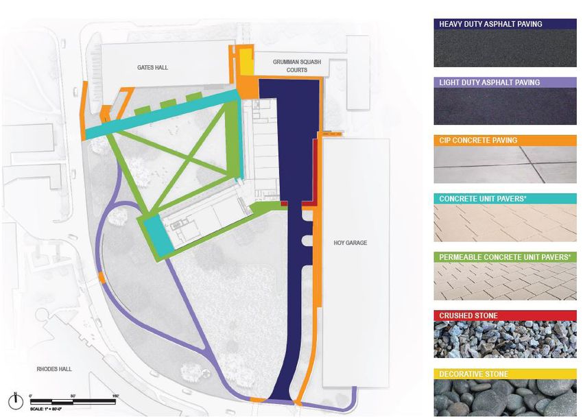
Site Materials
Site pavements are proposed to be heavy duty asphalt paving for the service drive/court, light duty asphalt paving
for sidewalks/paths along Hoy Road, concrete paving for sidewalks primarily adjacent to Gates Hall and Hoy Garage,
concrete unit pavers for sidewalks and plazas around the new greenspace and a small area of crushed stone adjacent to
the service court and beneath the bridge connection to Gates Hall.
Figure 9. Site Materials Diagram.
32Project Narrative
Parking
A small surface parking lot exists at the southern end of the site along Hoy Road. It has 26 existing parking spaces,
which will be removed as part of the project, along with a parking booth. Cornell manages all parking as a campus-
wide district and will continue to be in compliance with its Traffic Demand Management Plan and requirements for the
U-1 zoning including the development of this project.
There are four ADA parking spaces proposed along the service drive. An accessible sidewalk borders the service drive/
court, providing access to a mid-bay connection into the Hoy Garage.
Site Lighting
The site of the proposed building will include dark sky compliant, LED low-voltage lighting that complies with Cornell
standards for pedestrian spaces. Additional safety and security lighting will be provided for the service drive/court
and pedestrian circulation. Color temperature is proposed at 3000k throughout the project. Site lighting layout and
photometrics can be found in the technical drawing set.
Signage
Exterior signage will be in compliance with Cornell standards and will be compatible with nearby signage elements.
Energy
The building is designed with high-performance building materials to meet or exceed Cornell University’s sustainability
goals, and to achieve LEED Silver certification. The proposed building will comply with the Ithaca Energy Code
Supplement and NYStretch Energy Code.
The design team focused on including high-performance envelope strategies, including glazing selection, shading and
envelope assemblies optimization, as well as calculating water use and savings, coordinating stormwater management
strategies, and developing recommendations for carbon savings and healthy interiors.
The proposed mechanical design consists of multiple systems. This includes Variable Air Volume (VAV) Air Handling
Units (AHUs) with energy recovery wheels serving all terminal units. Active and passive chilled beam units are
provided for smaller offices and meeting rooms. Variable volume fan coils are provided for large open office areas,
classrooms, and larger meeting room type areas. VAV with reheat terminal units serve sections of the building such as
the maker spaces and common/entry areas. All AHUs are served with hot water (HW) heating coils and chilled water
(CHW) cooling coils.
The project shall be constructed using a solar-ready design approach. Building infrastructure to support the installation
of a rooftop solar photovoltaic array (power and communications conduit, electrical system connection points) will be
provided as part of this project. The University intends to pursue a solar photovoltaic power purchase agreement from
a third-party vendor. The facility rooftop can support a solar PV array of approximately 150kW size and will consist of
inverters, photovoltaic solar panels, integral-mounted AC/DC disconnect switches within inverters, and exterior roof-
mounted weatherproof DC disconnect switches.
Energy efficient LED lighting will be used for the interior and exterior. Daylighting controls in combination with
occupancy-based sensing are proposed.
The new building will be cooled using the campus chilled water utility, which is supplied by the Lake Source Cooling
district cooling system. The building mechanical systems will allow the building to operate using low temperature hot
water from the University district heating loop. While the building will be initially supplied with steam from the district
heating system, the installed equipment will be designed and sized to operate using low temperature hot water, which
will allow for easy conversion to a renewably generated hot water distribution district system in the future.
33Project Narrative
Site Utilities
Existing Conditions
Existing electric, gas, telecommunication, and chilled water services are provided near the site along Hoy Road.
Existing hot water services are available from Gates Hall.
Proposed Improvements
The project is not expected to impact the existing gas system, nor will new gas service be required for the project.
Electric services to the proposed building will be provided from the Cornell distribution system located on the west
side of Hoy Road. Telecommunication services to the proposed building will be provided from the existing Cornell
network. The new services will connect to existing distribution near the south end of the Hoy Road parking garage. The
project does not include steam system improvements or services. Chilled water service to the proposed building will
consist of new chilled water supply and return piping from the existing distribution pipes in Hoy Road. Hot water system
improvements will include new supply and return piping from Gates Hall.
Site Stormwater Management
Existing Conditions
Soils on the existing site are in most cases covered with artificial turf associated with the existing baseball field. The
field is relatively flat with existing grades sloping down from the infield at the northeast corner of the site to the outfield
fence and perimeter of the field to the south and west. The area of the site between the turf field and Hoy Road, which is
landscaped primarily with lawn and asphalt paths, slopes down more steeply towards the roadway. Based on previous
geotechnical reports the soils underlaying the site can be classified as Hydrologic Soils Group C or D. The site is
located above the 100-year flood level according to Federal Emergency Management Agency (FEMA) mapping.
Drainage for the existing turf field is provided by an array of drain tiles running from east to west and connecting to
drains which discharge to the larger university-owned storm sewer collection system. Stormwater runoff from the
landscape areas and pedestrian path along the west and south edges of the site drains overland to the easterly curb line
of Hoy Road where it is collected by drainage inlets in the roadway.
The larger storm system associated with the site collects runoff from most areas of the Hoy Road roadway, the Gates
Hall site as well as areas along Campus Road to as far north as Barton Hall. The larger system continues generally to
the west where it eventually discharging to Cascadilla Creek near the College Avenue bridge.
Proposed Improvements
Stormwater drainage improvements will include drains for the proposed building to the site drainage system. Site
drainage will be provided with storm sewer piping to collect and convey runoff from the site. The project is required
to prepare a Full Storm Water Pollution Prevention Plan (SWPPP) in compliance with the NYSDEC General Permit for
Construction Activities and City of Ithaca stormwater regulations. The SWPPP will include requirements for temporary
erosion control practices to be installed and maintained during construction, as well requirements for the construction,
operation and maintenance of permanent practices to remain after construction is complete. Obtaining permit coverage
for stormwater discharges under the general permit will require submission to the NYSDEC of a Notice-of-Intent along
with an MS4 SWPPP Acceptance Form approved by the City of Ithaca Stormwater Officer.
The project will change the soil cover on the site by replacing the artificial turf field with new pavements, buildings
and landscaped areas, and post-construction Stormwater Management Practices (SMP’s) will be required to manage
runoff from the completed site. The SMP’s will provide water quality treatment for the water quality volume (“WQv”)
of the finished site computed in accordance with the NYSDEC standards. The project is not expected to be subject to
the NYSDEC Total Maximum Daily Load (“TMDL”) for Phosphorous in Cayuga Lake which is currently in draft form.
The TMDL standards, if and when determined, will likely require projects to provide enhanced phosphorous removal in
34Project Narrative
accordance with Chapter 10 of the NYSDEC design manual.
The SMP’s for the project will also be required to provide a certain amount or runoff reduction volume (“RRv”) or
retention of runoff in order to comply with the general permit. Given the site soils are HSG C and D, the amount of RRv
required by the permit is reduced by a reduction factor of S=0.30 or 30% of the WQv of the finished site. Strategies to
provide the required RRv include pervious pavements, tree planting, and other standard or alternative practices with RRv
capacity. The currently identified SMP’s include a bioretention filter practice near the northwest corner of the site and a
second filter practice south of the proposed building and west of the eastern access drive. The NYSDEC considers such
filter practices as ‘standard’ SMP’s which inherently has RRv capacity.
35This page has been intentionally left blank.
Full Environmental
Assessment Form

                     37
Full Environmental Assessment Form
Part 1 - Project and Setting
Instructions for Completing Part 1
Part 1 is to be completed by the applicant or project sponsor. Responses become part of the application for approval or funding,
are subject to public review, and may be subject to further verification.
Complete Part 1 based on information currently available. If additional research or investigation would be needed to fully respond to
any item, please answer as thoroughly as possible based on current information; indicate whether missing information does not exist,
or is not reasonably available to the sponsor; and, when possible, generally describe work or studies which would be necessary to
update or fully develop that information.
Applicants/sponsors must complete all items in Sections A & B. In Sections C, D & E, most items contain an initial question that
must be answered either “Yes” or “No”. If the answer to the initial question is “Yes”, complete the sub-questions that follow. If the
answer to the initial question is “No”, proceed to the next question. Section F allows the project sponsor to identify and attach any
additional information. Section G requires the name and signature of the applicant or project sponsor to verify that the information
contained in Part 1is accurate and complete.
A. Project and Applicant/Sponsor Information.
Name of Action or Project:
Cornell University, New Computing and Information Science Building
Project Location (describe, and attach a general location map):
Hoy Road. See attached narrative and visual materials
Brief Description of Proposed Action (include purpose or need):
Cornell University is proposing to construct a Computing and Information Science (CIS) building that will create a dynamic new environment for the
growing areas of Computer Science, Information Science, and Statistics and Data Science. The proposed building will be located adjacent to the south of
the Bill and Melinda Gates Hall (Gates Hall), in the area currently occupied by Hoy Baseball Field. The building is proposed as four-stories tall,
approximately 133,000 square feet, and will include a diversity of spaces for students, faculty, and staff. The project site will be redeveloped to include a
new quad along with native landscaping and plaza spaces. The site will also include pedestrian/vehicular circulation, ADA parking, and a service drive/
court.
Name of Applicant/Sponsor: Telephone: 607-277-1400
Kimberly Michaels, Agent TWM, a Fisher Associates Landscape Architecture Studio E-Mail: kam@twm.la
Address: 1001 West Seneca Street, Suite 201
City/PO: Ithaca State: Zip Code:
NY 14850
Project Contact (if not same as sponsor; give name and title/role): Telephone: 607.255.1399
Patrick Conrad, Project Manager E-Mail: pcc23@cornell.edu
Address:
Humphreys Service Building, 639 Dryden Road
City/PO: State: Zip Code:
Ithaca NY 14850
Property Owner (if not same as sponsor): Telephone:
Cornell University E-Mail:
Address:
City/PO: State: Zip Code:
Ithaca NY 14850
Page 1 of 13
FEAF 2019B. Government Approvals
B. Government Approvals, Funding, or Sponsorship. (“Funding” includes grants, loans, tax relief, and any other forms of financial
assistance.)
Government Entity If Yes: Identify Agency and Approval(s) Application Date
Required (Actual or projected)
a. City Counsel, Town Board, 9 Yes ✔ 9 No
or Village Board of Trustees
b. City, Town or Village 9 Yes 9 No
✔ City of Ithaca Planning Board
May 16, 2022
Planning Board or Commission
c. City, Town or 9 Yes ✔
9 No
Village Zoning Board of Appeals
d. Other local agencies 9 Yes 9 No
✔ City of Ithaca MS4: SWPPP Acceptance
e. County agencies 9 Yes 9 No
✔ 239 Review
f. Regional agencies 9 Yes ✔
9 No
g. State agencies 9 Yes 9 No
✔ NYSDEC: SPDES GP-0-20-001 (stormwater)
NYS-OPRHP: PRHPL, Section 14.09
h. Federal agencies 9 Yes ✔
9 No
i. Coastal Resources.
i. Is the project site within a Coastal Area, or the waterfront area of a Designated Inland Waterway? 9 Yes ✔
9 No
ii. Is the project site located in a community with an approved Local Waterfront Revitalization Program? 9 Yes ✔
9 No
iii. Is the project site within a Coastal Erosion Hazard Area? 9 Yes ✔
9 No
C. Planning and Zoning
C.1. Planning and zoning actions.
Will administrative or legislative adoption, or amendment of a plan, local law, ordinance, rule or regulation be the 9 Yes ✔
9 No
only approval(s) which must be granted to enable the proposed action to proceed?
• If Yes, complete sections C, F and G.
• If No, proceed to question C.2 and complete all remaining sections and questions in Part 1
C.2. Adopted land use plans.
a. Do any municipally- adopted (city, town, village or county) comprehensive land use plan(s) include the site 9 Yes 9 No
✔
where the proposed action would be located?
If Yes, does the comprehensive plan include specific recommendations for the site where the proposed action 9 Yes ✔
9 No
would be located?
b. Is the site of the proposed action within any local or regional special planning district (for example: Greenway; 9 Yes ✔
9 No
Brownfield Opportunity Area (BOA); designated State or Federal heritage area; watershed management plan;
or other?)
If Yes, identify the plan(s):
_______________________________________________________________________________________________________
________________________________________________________________________________________________________
________________________________________________________________________________________________________
c. Is the proposed action located wholly or partially within an area listed in an adopted municipal open space plan, 9 Yes ✔
9 No
or an adopted municipal farmland protection plan?
If Yes, identify the plan(s):
________________________________________________________________________________________________________
________________________________________________________________________________________________________
________________________________________________________________________________________________________
Page 2 of 13You can also read