National Aeronautics and Space Administration
←
→
Page content transcription
If your browser does not render page correctly, please read the page content below
National Aeronautics and Space Administration

                                                NASA Sounding Rockets
                                                Annual Report 2021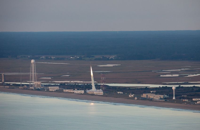
virtually. Content for the virtual workshop was developed by the PI Institu-
Message from the Chief
tion, Colorado Space Grant Consortium. These experiments, as well as the Table of Contents
RockSat-C experiments were flown in June 2021. RockSat-X, with the most Message from the Chief 2
advanced student experiments, was flown in August 2021.
Sounding Rockets Overview 4
One of the highlights for 2021 was the range setup trip to Australia. The Astrophysics Missions 2021 14
launches, originally planned for 2020, are now on schedule for 2022. Three Dual-channel Extreme Ultraviolet Continuum Experiment (DEUCE) 16
astrophysics missions will be launched from this new range, Equatorial Cosmic Infrared Background Experiment-2 (CIBER) 17
Launch Australia (ELA), near Nhulunbuy, Northern Territory. Launchers and Geospace Missions 2021 19
ground support equipment were setup during the summer 2021, and ELA is Kinetic-scale Energy and momentum Transport eXperiment (KINET-X) 20
continuing site preparations to ensure range is ready before launch operations Vlf trans-Ionospheric Propagation Experiment Rocket (VIPER) 21
commence. This is an incredible step toward realizing a vision of returning to DYNAMO-2 22
Australia for southern hemisphere research after almost three decades. Kudos
Solar Physics 2021 25
to the setup team from SRPO, NSROC, and the Wallops Range who endured
Spatial Heterodyne Interferometric Emission Line Dynamics Spectrometer (SHIELDS) 26
a two week quarantine, then several weeks of hard work in intense Australian
Giovanni Rosanova, Jr. Extreme Ultraviolet Normal-Incidence Spectrograph (EUNIS) 27
heat to establish this capability.
Chief, Sounding Rockets Program Office Marshall Grazing Incidence X-ray Spectrometer (MaGIXS) 28
Solar Dynamics Observatory - EUV Variability Experiment (SDO-EVE) 29
Thanks to the extraordinary resilience and grit of the people in the sounding After some schedule slips due to COVID, the launch manifest is filling up
rockets program, both civil service and contractor, we had a very successful for the near future. A total of 22 launches are currently manifested (two have
Reimbursable Missions 2021 31
fiscal year 2021. Fourteen missions, covering five disciplines, launched from two already been launched) for FY 22. Similarly, FY 23 has 22 missions manifested.
Aerodynamic Buffet Flight Test (ABFT) 32
ranges, were flown with a success rate of 100%. While the pandemic has made Future launches include some very exciting projects: Mars Ascent Vehicle
High Operational Tempo (HOTShot) 33
the work environment different in many ways, our adherence to COVID -19 (MAV) flight tests for a collaborative team from Jet Propulsion Laboratory Education Missions 2021 34
protocols, such as masking and social distancing, allowed missions to be inte- (JPL) and Marshall Space Flight Center (MSFC) and Advanced Supersonic RockOn 36
grated and flown in support of NASA’s scientific objectives. Kudos to the entire Parachute Inflation Research and Experiments (ASPIRE) 2 for JPL. These RockSat-X 37
staff for stepping up during these difficult times. projects include launches during FY 24 and 25. Additionally, we are looking Technology Development 40
forward to supporting a solar physics campaign from Poker Flat Research Sounding Rockets Program Technology Roadmap 44
Our missions this year included four Solar physics flights: the Extreme Ultra- Range, AK in FY 24. Three missions will be launched to study solar flares. The
STEM Engagement 49
violet Normal-Incidence Spectrograph (EUNIS) and the Marshall Grazing operations will be similar to our Geospace Science missions, and the launches
Wallops Rocketry Academy for Teachers and Students 50
Incidence X-ray Spectrometer (MaGIXS) studied the solar corona in two differ- will occur during a launch window of approximately two weeks. Scientists
Internships and Outreach 51
ent wavelengths; Spatial Heterodyne Interferometric Emission Line Dynamics will monitor solar activity and evaluate flare intensity before committing to a
Spectrometer (SHIELDS) investigated particles entering the heliopause; Solar launch. We are keen to expand the operations envelope for our solar research- On the Horizon 53
Dynamics Observatory - EUV Variability Experiment (SDO-EVE) calibrated ers. Charts 56
sensors onboard SDO. Astrophysics missions included observations in both Sounding Rocket Launch Sites 56
the Extreme Ultraviolet (Dual-channel Extreme Ultraviolet Continuum On November 30, 2021, John Hickman, Deputy Chief for the Sounding Sounding Rocket Vehicles 57
Experiment, or DEUCE) and the Infrared (Cosmic Infrared Background Rockets Program, retired after 36 years of service to NASA. Several long serv- Sounding Rocket Vehicle Performance 58
Experiment-2, CIBER-2) parts of the spectrum. Four missions were flown ing NSROC employees, including 41-year sounding rocket veteran, Jim Diehl, Sounding Rockets Program Office personnel 60
for Geospace Science, and, although infrequent for this discipline, all were also will retire by the end of the calendar year. I wish to thank John, Jim, and Contact Information 61
launched from Wallops Island, VA. The Kinetic-scale Energy and momentum the others for their outstanding contributions to the program, and wish them
Transport eXperiment (KINET-X) mission focused on energy and momentum a safe, healthy, and enjoyable retirement. Their diligence and efforts have made
transport between different regions of space, VLF trans-Ionospheric Propagation all the difference throughout the years.
Experiment Rocket (VIPER) studied very long frequency radio waves and their
propagation along the Earth's magnetic field lines, and DYNAMO-2 studied As the year nears its end, we often take stock of the events, good and bad, that
the atmospheric dynamo create by global systems of currents. Additionally, two make each year unique. Needless to say, 2020 and 2021, were overwhelmed
reimbursable missions were flown. NASA Langley Research Center studied with health concerns due to the COVID-19 pandemic, however, I am, as
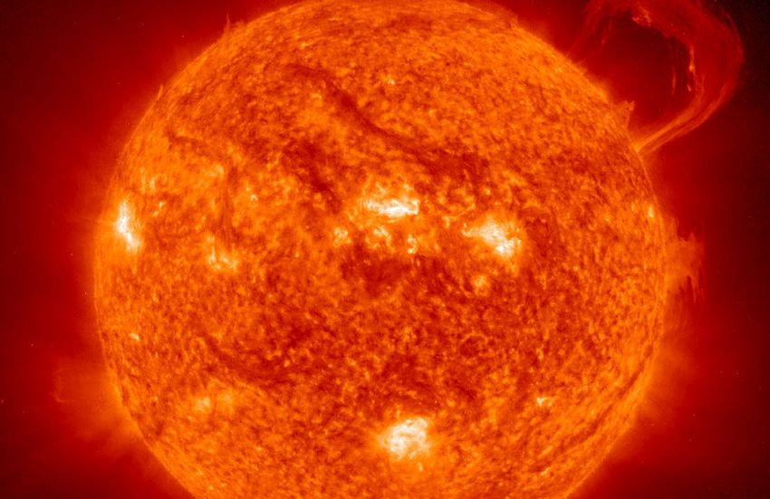
transonic buffet acting on launch vehicles, using a vehicle specially designed for always, inspired by the individuals that form the great teams that support the Cover photo: VIPER launch from Wallops Island, VA.
this purpose, and Sandia National Laboratories flew a High Operational Tempo, sounding rockets program. Without the team effort, excitement, and the sense
Credit: Wallops Imaging Lab
or HOTShot, mission testing newly developed components for space flight on a of duty exhibited by each of you, the program would not be what it is.
Terrier-Improved Malemute.
I wish all of you a great 2022. Onward and upward!
We were delighted to welcome back our student missions after a one-year delay
due to COVID. Both the RockOn and RockSat-X missions were flown in 2021.
RockOn, the workshop flight opportunity, is the first step in developing student
2 experiments for spaceflight. In the past the workshop has been held at Wallops
Giovanni Rosanova, Jr. 3
Flight Facility, but due to COVID restrictions this year’s workshop was held
Science with Sounding Rockets

    Sounding                                                                                                            In 1957 scientists participating in the International Geophysical Year (IGY) had available to them rockets as

    Rockets                                                                                                             research tools for the first time in history. They took full advantage of these new assets, and launched a total of
                                                                                                                        210 rockets from 7 different sites as part of the United States contribution to the IGY.

    Overview
                                                                                                                        The research ranged from atmospheric sciences to astronomy. Ionospheric soundings
                                                                                                                        included direct electron density measurements and detailed mapping of the E and F
                                                                                                                        regions.

    The Sounding Rockets Program supports the NASA Science Mission Directorate’s strategic vision and goals             IGY 1957 firmly established sounding rockets as viable tools for science and proved
    for Earth Science, Heliophysics and Astrophysics. The 20+ suborbital missions flown annually by the program         their utility for in-situ measurements, quick response, and temporal and geographic
    provide researchers with unparalleled opportunities to build, test, and fly new instrument and sensor design        mobility. The utilization of sounding rockets for science has continued with undimin-
    concepts while simultaneously conducting world-class scientific research. Coupled with a hands-on approach to       ished importance.
    instrument design, integration and flight, the short mission life-cycle helps ensure that the next generation of
    space scientists receive the training and experience necessary to move on to NASA’s larger, more complex space      Heliophysics, Astrophysics, Geospace science and Aeronautics benefit from sounding
    science missions. The cost structure and risk posture under which the program is managed stimulates innova-         rockets. Advantages such as the quick response to scientific events, low cost, and mo-
    tion and technology maturation and enables rapid response to scientific events.                                     bile operations provide researchers with opportunities to conduct world class science.

    With the capability to fly higher than many low Earth orbiting satellites and the ability to launch on demand,      Some of the highest resolution spectral data of the Sun are recorded with telescope
    sounding rockets offer, in many instances, the only means to study specific scientific phenomena of interest to     payloads flying on sounding rockets. Payload recovery yields significant cost savings by
    many researchers. Unlike instruments onboard most orbital spacecraft or in ground-based observatories, sound-       ensuring that sensors, one-of-a-kind telescopes, cameras and recorders are available for
    ing rockets can place instruments directly into regions where and when the science is occurring to enable direct,   reflight on future missions.
    in-situ measurements. The mobile nature of the program enables researchers to conduct missions from strategic
    vantage points worldwide.                                                                                           As research tools, sounding rockets are key to the study of the near Earth space envi-
                                                                                                                        ronment; in fact, they are the only means of collecting in-situ data in the ionosphere.
    Telescopes and spectrometers to study Solar and Astrophysics are flown on sounding rockets to collect unique        Several launch sites in the arctic region enable studies of phenomena such as mag-
    science data and to test prototype instruments for future satellite missions. The program’s rapid response          netic re-connection, ion outflows and the effects of Joule heating. Understanding the
    capability enabled scientists to study the Supernova 1987A before it faded from view. Currently, new detectors,     fundamental processes that govern the Sun-Earth space environment will enhance our
    expected to revolutionize X-ray astronomy, are under development and have been successfully tested on sound-        ability to more accurately predict the solar storms that can disrupt power grids and
    ing rocket flights. An important aspect of most satellite missions is calibration of the space based sensors.       satellite-based information systems on Earth.

                                                                                                                        In the high energy and the ultraviolet and visible parts of the spectrum, Astrophysics
                                                                                                                        uses sounding rockets to test new instruments on unique scientific missions. Sub-sys-
                                                                                                                        tems, developed by NASA, provide unprecedented pointing accuracy for stellar target-
                                                                                                                        ing, yielding high resolution spectra and potentially leading to new ground breaking
                                                                                                                        discoveries about our own galaxy. rockets offer calibration and validation flights for
                                                                                                                        many space missions, particularly solar observatories such as the Thermosphere-Ion-
                                                                                                                        osphere-Mesosphere-Energetics-Dynamics (TIMED) satellite, the Solar Heliospheric
                                                                                                                        Observer and the future Solar Dynamics Observatory (SDO).

                                                                                                                        Additionally, sounding rockets are well suited for testing new technologies for future space missions. For ex-
                                                                                                                        ample, parachute technologies for the Mars 2020 mission were tested on sounding rockets.
4                                                                                                                                                                                                                                             5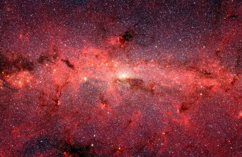
End-to-End Mission Support
    The NASA Sounding Rocket Program provides comprehensive mission support and management services from
    concept through post flight data distribution. This end-to-end support capability enables the Principal Investi-
    gator (PI) to focus on the research aspect of the mission.

    Extensive experience, over 2,500 missions flown, has lead to streamlined processes and efficient design, manu-
    facturing and assembly techniques. Management and technical support is provided for all facets of a mission
    and includes engineering design, manufacturing, integration, and testing and evaluation. Periodic reviews are
    conducted to ensure mission requirements are being met on time and on budget.

    Launch Vehicles

                                                                                                                                    Sounding Rocket Vehicle Performance
                                                                                                                                    By NSROC Flight Performance

                                                                                                                       Payload Design
                                                                                                                       The payload design process begins immediately after the Mission Initiation
                                                                                                                       Conference (MIC) is completed. Initial flight requirements and schedules
                                                                                                                       are discussed at the MIC.

                                                                                                                       All payload components, mechanical and electrical systems,
                                                                                                                       telemetry, recovery and other sub-systems are designed using
                                                                                                                       state-of-the-art software, modelling and analysis tools.
                                                                                                                       3-D visualization tools facilitate the iterative design
                                                                                                                       process by allowing flexibility in design updates and
                                                                                                                       changes. The integrated multi-disciplinary design
                                                                                                                       methods are effective in meeting the needs of                                3D model of payload.
                                                                                                                                                                                                    By NSROC Mechanical Section
                                                                                                                       the PI.

         Sounding Rocket Vehicles
         By NSROC Mechanical Section

    The Sounding Rocket Program offers multiple proven launch vehicles to meet the needs of most researchers.
    New vehicles are brought online periodically to meet customer requirements and enhance capability. Currently,
    13 vehicles are provided “off-the-shelf ” and range in performance from a single stage Orion to a four stage
    Black Brant XII-A and Oriole IV.

6                                                                                                                                                                                                                                 7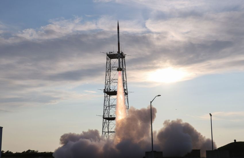
Manufacturing
    Extensive in-house manufacturing capability is vital in a program with many customization requirements. The             Electrically operated vacuum doors are available for most tele-
    machine shop includes a vast assortment of machinery such as Computer Numerical Controlled (CNC) mill-                  scope payloads.
    ing machines, lathes, welders, sheet metal breaks/shears/rollers and additional tools/processes to support the
    mechanical needs of the program. A waterjet cutting machine enables fast manu facturing of small parts in large         Deployment mechanisms actuated by pyrotechnic, electric or
    quantities.                                                                                                             mechanical means are available for doors, booms, shutters, etc.

                                                                                                                            In instances where missions require measurements from multiple
                                                                                                                            widely spaced platforms a special payload is created to permit
                                                                                                                            separation into several sub-payloads. Each sub-payload has it’s       Open shutter door with instrument visible during testing at
                                                                                                                                                                                                  Wallops. Photo by: Berit Bland/NSROC
                                                                                                                            own Telemetry link to transmit all science and housekeeping data
                                                                                                                            for that section.
    Machine shop in Building F-10 at Wallops Flight Facility. Photos by: Berit Bland/NSROC
                                                                                                                            Telemetry systems are designed to support the requirements of a mission and the configuration is determined by
    Assembly
                                                                                                                            the complexity of the experiment, the configuration of the detectors, and the size of the rocket. Systems vary in
    Payload electrical and mechanical assembly begins with
                                                                                                                            complexity from a single link with no command or trajectory equipment to systems containing as many as eight
    decks, longerons and electrical wiring and ends with the
                                                                                                                            downlinks, and complex command and trajectory hardware.
    integration of all sub-systems and science instruments.
    Electrical and mechanical technicians are assigned to a
                                                                                                                            When payload recovery is required, flight performance engi-
    mission at the MIC and, to the extent possible, stay with
                                                                                                                            neers predict the radius within which the payload will land; the
    the assigment through flight, contributing greatly to a
                                                                                                                            re-entry path is tracked by radar and the recovery achieved by
    responsive and customer focused program.
                                                                                                                            parachuting the payload to a land or water landing. Recovery is
                                                                             Payload assemblies during integration.         accomplished by boat, helicopter or land vehicle. Additionally,
    Sub-systems                                                              Photo by: Berit Bland/NSROC
                                                                                                                            payloads may be designed with gas or liquid tight bulkheads fit-
    The Sounding Rocket Program provides standard sub-
                                                                                                                            ted with sealed passages for electrical wiring or piping.
    systems such as recovery, ACS, and the S-19 boost guidance system as required by the mission profile. Custom
    systems such as telemetry, based on heritage components, are also available.                                                                                                                 Payload recovery at White Sands Missile Range, NM. Photo
                                                                                                                            Testing and Evaluation                                               by: Visual Information Branch/WSMR.
                                                                                                                            The launch and flight phases of a sounding rocket mission are
    The boost guidance system controls the path of the rocket during the initial 18 seconds of flight where air den-
                                                                                                                            stressful events for the scientific payload. The sum of the stressful elements to which such a payload is exposed is
    sity is adequate to permit course correction by means of movable fins. The vehicle pitch and yaw angles are de-
                                                                                                                            called the “payload environment.” A rigorous environmental test plan helps to ensure that a payload will survive
    tected by a gyro platform which produces corresponding output signals; the signals are processed in an autopilot
                                                                                                                            this hostile environment and continue working through the successful completion of its mission.
    and, after roll resolution, are used as servo command signals.

                                                                                                                            The ultimate purpose of environmental testing and evaluation is to determine if a particular payload can survive
    Several types of sensors are used, singly or in combina-
                                                                                                                            the environment specific to the vehicle configuration designated for that mission. A comprehensive preflight
    tion to provide payload attitude information. They include
                                                                                                                            qualification process involves subjecting the complete payload, in its flight configuration, to a series of environ-
    Magnetometers, Gyroscopes, Solar/Lunar Sensors, Horizon
                                                                                                                            mental elements such as vibration, bending, heating, spin, de-spin, and vacuum exposure.
    Sensors, Television Cameras, and Film Cameras. The Atti-
    tude Control System positions the payload as required using
    compressed gas that is released through small nozzles located
    on the payload skin.
                                                                               Magnetic Attitude Control Systems testing.
8                                                                              Photo by: Berit Bland/NSROC
                                                                                                                                                                                                                                                                9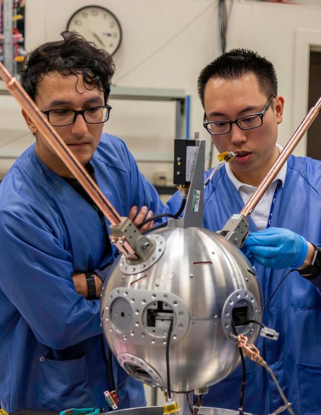
Vibration Testing                                                                                                                      Mass Properties Measurements
     The test specifications used for a particular payload are determined                                                                   A payload’s mass properties – weight, center of gravity, and moments
     by the ignition and burn parameters of the rocket motors used for                                                                      of inertia – are calculated during the design phase. These numbers are
     that launch. Vibration tests are performed in three payload axes -                                                                     incorporated into the early performance and ACS analyses to verify flight
     thrust and two orthogonal laterals. There are two types of vibra-                                                                      and control stability. Design changes are incorporated to enhance stability,
     tion inputs – sine and random – for each axis. Shock pulses can                                                                        to incorporate customer requirement changes, and to reacquire stability in
     also simulate motor ignition or payload separation events. A pay-                                                                      an iterative process that may continue right up to the brink of test time.
     load’s response to an input vibration depends on the size, weight                                                                      Accurate mass property measurements of the launch and control configura-
     distribution, and harmonic frequencies of the assembly. A test is                                                                      tions are used to confirm the theoretical calculations and to provide the
     considered successful when the payload continues to perform all          Payload on vibration table. Photo by: Berit Bland/NSROC       performance and ACS analysts with data to be used in the final pre-flight       Payload place on mass properties measurement table.
                                                                                                                                                                                                                            Photo by: Berit Bland/NSROC
     functions as designed after each round of vibration.                                                                                   performance predictions.

     Bend Testing                                                                                                                           Static And Dynamic Balancing
     The pressure effects of high velocity atmospheric flight create bending moments along the                                              Dynamic imbalances in the launch configuration could cause an unstable flight profile
     length of a payload, with the maximum moment occurring at the base where the payload                                                   such as coning, which would decrease apogee altitude and experiment data collection
     attaches to the motor. The severity of this moment and the resultant payload bending are                                               time. Static or dynamic imbalances in the control configuration could degrade the
     predicted during a detailed performance analysis prior to testing. Commonly, deflection                                                attitude control system’s ability to align property and acquire the mission target(s).
     is measured at the tip to determine the sum of all joint deflections under the anticipated                                             The balance facility uses technology similar to that used for automobile tires but it is
     bending moment. A test is considered successful if the total tip deflection is equal to or less                                        more accurate. Imbalances are first detected, and adjusted using lead or brass correction
     than that predicted in the performance analysis, and if the deflection at an individual joint is                                       weights, then re-measured to verify that the problem has been resolved. Each payload
     within acceptable limits.                                                                                                              has its own imbalance limits, determined by the launch, control, and mass property
                                                                                                              Bend testing of payload.      parameters specific to that payload.
                                                                                                              Photo by: Berit Bland/NSROC
     Spin Testing - Operational and Deployment
     Sounding rockets are spin stabilized. Motor vehicle fin cants ensure that the                                                          Thermal Testing
     assembly begins to spin-up as soon as it leaves the launch rail. The amount                                                            Thermal testing verifies the ability of a payload or component to withstand elevated
     of spin at any given time in the flight sequence is referred to as the roll rate.                                                      temperatures, caused by friction or onboard heat souces such as a transmitter. Several
                                                                                                                                                                                                                                          Payload being prepared for balancing.
     Payloads often use the resultant centrifugal force to deploy doors, sensors, and                                                       thermal testing chambers are available to accommodate components and systems of               Photo by: Berit Bland/NSROC
     other devices. Some deployments increase the spin inertia and thereby decrease                                                         various sizes.
     the roll rate. Some payloads are designed to operate at zero roll rate and de-spin
     weights can be deployed to achieve that effect. Roll rate gradients occur during                                                       Vacuum Testing
     the intervals of rate change. Maximum spin rates, maximum rate gradients, and                                                          Vacuum testing is conducted to verify that component shields and conduc-
     even the entire flight sequence spin rate profile can be reproduced in the spin                                                        tive heat sinks are designed such that the components will survive space
     test bay.                                                                                                                              conditions and function properly throughout all phases of exo-atmospheric
                                                                                                                                            flight. Out-gassing is a release of molecules from a material caused by expo-
     Most spin deployments are performed in the same facility and photo or video                                                            sure to vacuum and/or heat. Scientific detectors are often very sensitive to
     data are collected. Using this optical data, in conjunction with telemetry signal                                                      contamination and must be isolated from materials that out-gas excessively.
                                                                                             Payload with deployed booms and
     data monitored during the tests, the payload team can verify that payload               instruments. Photo by: Berit Bland/NSROC       Materials that cannot be isolated from the detectors must be thoroughly
     instruments are functioning properly throughout these events, and that the                                                             cleaned and then forced to out-gas completely by high temperature baking
     deployments can be performed successfully in flight, and/or they can identify problems which need to be ad-                            and other methods. Subsequent thermal vacuum testing can verify that            Payload ready to enter the thermal-vacuum chamber.
                                                                                                                                                                                                                            Photo by: Berit Bland/NSROC
     dressed.                                                                                                                               these materials have been rendered inert.
10                                                                                                                                                                                                                                                                                11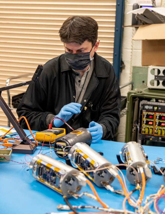
Launch operations support
         Both established and temporary launch sites world wide are available to accommodate the needs of the PI.
         Established launch ranges exist in Alaska, New Mexico, Virginia, Norway, Sweden and Australia. Coupled with
         temporary sites in Greenland, Marshall Islands, Puerto Rico and Brazil provide extensive access to phenomena
         of interest to the science community.

         The Sounding Rockets Program, in cooperation with the Wallops Range, provide all necessary personnel and
         equipment to conduct successful missions anywhere in the world.

         Additionally, ground and flight safety analyses are provided by the NASA Safety group at Goddard Space Flight
         Center’s Wallops Flight Facility, home of the Sounding Rockets Program.

                                                                           13
                                                     9       10            11
                                   3                                         12

                                        4        8
                2
                                                 7

     1
                                                         6
                                            5

                                                                                                                       14

                        Past and present world wide launch sites used by the Sounding Rockets Program
                                                to conduct scientific research:
                    1. Kwajalein Atoll, Marshall Islands          8. Wallops Island, VA
                    2. Barking Sands, HI                          9. Fort Churchill, Canada *
                    3. Poker Flat, AK                             10. Greenland (Thule & Sondre Stromfjord) *
                    4. White Sands, NM                            11. Andøya, Norway
                    5. Punta Lobos, Peru *                        12. Esrange, Sweden
                    6. Alcantara, Brazil *                        13. Svalbard, Norway
                    7. Camp Tortuguero, Puerto Rico *             14. Australia (Equatorial Launch Australia (ELA) & Woomera)

                                                                  * Inactive launch sites

                                                                                                                                RockSat-X 2021 launching from Wallops Island, VA
                                                                                                                                Photo by: Berit Bland/NSROC
12                                                                                                                                                                                 13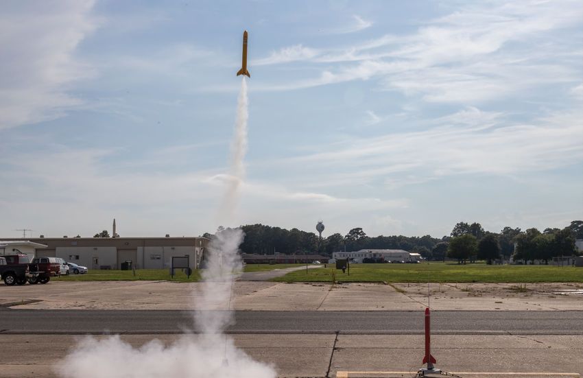
Astrophysics
Missions 2021
In 2021 two Astrophysics missions were flown. The Dual-channel Extreme Ultraviolet Continuum Experiment
(DEUCE) measured how much ionizing photons B stars, such as the target star for this mission ß Canis
Major, produce, and the Cosmic Infrared Background Experiment-2 conducted multi-band measurements of
extragalactic background light (EBL) anisotropy.

                                                                                                          Milky Way galaxy in this 2006 infrared image from the Spitzer Space Tele-
                                                                                                          scope.

                                                                                                          Image credit: JPL-CALTECH/NASA, S. STOLOVY, SSC

   14                                                                                                                                                                                 15
Dual-channel Extreme Ultraviolet Continuum Experiment (DEUCE) Cosmic Infrared Background Experiment-2 (CIBER)
The Dual-channel Extreme Ultraviolet Continuum Experiment (DEUCE) is a spectrograph operating from CIBER-2 is a near-infrared rocket-borne instrument designed to
650 to 1100 Å. DEUCE measured how much ionizing photons B stars, such as the target star for this mission conduct comprehensive multi-band measurements of extragalactic
ß canis major, produce. DEUCE was successfully flown from White Sands Missile Range, NM on November 2, background light (EBL) anisotropy on arcsecond to degree angular
2020. scales. CIBER-2 builds on the successful measurements and proven
methodology of the predecessor CIBER-1 instrument.
Dual-channel Extreme Ultraviolet Continuum Experiment (DEUCE)
DEUCE has two modes; a low resolution, high throughput mode operating from 650 – 890 Å, and a high
resolution, low throughput channel from 650 – 1100 Å. The stellar brightness changes dramatically above 912 CIBER-2 investigated the spectral and spatial properties of the
Å and below 912 Å and therefore the two modes are necessary. The change in intensity is unknown, and may extragalactic near-infrared background, and required acquisition
range from 10/1 to 10,000/1. DEUCE measured the flux of local, bright, hot stars that have very little inter- of multiple targets with minimal contamination from terrestrial
vening absorbing material in the interstellar medium. There are no preexisting measurements of the flux of these sources of infrared emission.
types of stars in the critical 700 – 900 Å regime, and the fundamental objective of DEUCE is to understand
how bright these types of stars are in the 700 – 900 Å regime. The Extragalactic Infrared Background (EBL) is the integrated
light from all of the infrared sources in the Universe. In the near
Cosmic Infrared Background Experiment-2 (CIBER)
This was also a test flight for a new variant of the NASA ETD designed Autonomous Rocket Tracker (ART) For IR, these photons are produced by stars as a by-product of nucleo-
this mission two trackers were integrated into the nosecone and bolted to the skin. ART relays GPS coordinates synthesis. Measurement of the near IR EBL therefore constrains
to a remote user via the Iridium satellite network, and enables tracking and locating vehicle and payload parts the stellar content of the Universe.
after impact. This was the third flight for ART and the first of this configuration.
Data from CIBER-2 will help determine the origin and history of
CIBER-2 in the cleanroom at Wallops Flight Facility.
This was the third flight of DEUCE. EBL fluctuations by carrying out multi-wavelength imaging in 6
spectral bands from 0.5 to 2.0 µm.
CIBER-2 was specifically designed to help disentangle the reion-
ization signal from emission from sources at lower wavelength.
One of the primary CIBER-1 results was unexpectedly bright,
large-angle fluctuations at wavelengths of 1.1 and 1.6 microns,
which may be identified with stars flung outside of galaxies or
other new populations that result from large-scale structure forma-
tion. The CIBER-2 data set will give us our most complete view of Cleanroom inspection of CIBER-2.
the near-IR background to date.
DEUCE payload team before launch. DEUCE science team members with payload during recovery
Photo by: Visual Information Branch/WSMR operations.
Photo by: Visual Information Branch/WSMR
CIBER-2 science team in the Attitude Control Systems Lab at
Wallops Flight Facility.
Photos by: Berit Bland/NSROC
Principal Investigator: Dr. James Green/University of Coloardo• Mission Number(s): 36.368 UG Principal Investigator: Dr. Michael Zemcov/Rochester Institute of Technology • Mission Number(s): 36.281 UG
Launch site: White Sands Missile Range, NM • Launch date: November 2, 2020 Launch site: White Sands Missile Range, NM • Launch date: June 7, 2021
16 17
Geospace Missions 2021
     Three Geospace Science missions, all from Wallops Island, VA, were launched in 2021. Kinetic-scale
     Energy and momentum Transport eXperiment (KiNet-X), studied space plasmas, Vlf trans-Ionospheric
     Propagation Experiment Rocket (VIPER) studied very low frequency radio, or VLF, waves that are
     produced by both natural and artificial means, and Dynamo-2 studied the upper atmosphere and its
     interactions with the ionosphere.

                                          Background image: Wallops Island Launch Range
                                          NASA Photo
18                                                                                                        19
Kinetic-scale Energy and momentum Transport eXperiment (KiNet-X) Vlf trans-Ionospheric Propagation Experiment Rocket (VIPER)
KiNet-X was designed to study a very fundamental problem VIPER studied very low frequency radio, or VLF, waves that are
in space plasmas; how are energy and momentum transport- produced by both natural (e.g. lightning) and artificial means.
ed between different regions of space that are magnetically During the day these waves are trapped or absorbed by the Earth’s
connected? ionosphere. At night some of the waves escape through the iono-
Kinetic-scale Energy and momentum Transport eXperiment (KINET-X)
sphere and accelerate electrons in the Van Allen Radiation Belt.
Auroras, for example, are formed when particles in the
Earth’s near-space environment interact with the atmo- At night, the lower layers of the ionosphere are much less dense,
Vlf trans-Ionospheric Propagation Experiment Rocket (VIPER)
sphere. The electrons in Earth’s space environment and in and more of the VLF can leak through,propagate along the Earth's
the solar wind have relatively low energies; yet the aurora is magnetic field lines, and endup interacting with the high energy
generated by very high energy electrons. What is this energi- electrons trapped in the Van Allen Radiation Belts. The Van Allen
zation mechanism? Radiation belts, of intense energetic electron fluxes, cover a range
of distances from the Earth, from as close as 14,300 miles altitude
Another example of energy and momentum transport is (~4.4 Earth radii) out to 23,500 miles altitude (~7 Earth radii).
the Io-Jupiter interaction. Io is the most volcanically active GPS satellites orbit at around 4.4 Earth radii, and geosynchronous
object in the solar system and has a tenuous atmosphere. satellites at about 6.6 Earth radii. Satellites in those orbits are of-
The interaction between Io’s atmosphere and Jupiter’s ten engulfed by the Van Allen Radiation Belts and have to tolerate
space environment leads to an Io-induced auroral spot in the effects those energetic particles have on electronics and materi-
Jupiter’s atmosphere. We know the power generated by Io’s als. By making accurate measurements of the VLF electromagnetic
interaction, and we know the auroral power from the spot, fields and the properties of the ionosphere below, at, and above
but how are energy and momentum transported along the the absorption and reflection layers in the ionosphere, VIPER
KiNet-X launch from Wallops Island, VA. VIPER launch from Wallops Island, VA
connecting magnetic field line? KiNET-X is like a mini-Io Photo credit: Allison Stancil-Erwin/NASA provides a novel data set for comparison with existing numeri- Photo credit: Allison Stancil-Erwin/NASA
with two barium vapor clouds that were emitted from the calmodels of the fields and the ionosphere, as well asobservations
rocket’s payload to generate a magnetic field perturbation, made in the past of the escaping VLF radiation at higher altitudes
leading to energized electrons. and on the ground.
The KiNET-X experiment, with known input parameters, While many ground-based and orbital observations of the VLF
was designed to quantify the flow of energy to the elec- absorption/reflections/transmission have been made, VIPER is the
trons. In-situ instruments measured the energized electrons first mission to make measurements right in the region where all
directly. In addition, specialized cameras in Bermuda and on the action happens. There are models of what to expect in such
an aircraft were used to observe the interactions. regions, but actual measurements are key to pin down the details
of those models, as well as, to develop the instruments required to
The KiNet-X experiment consisted of a single rocket launch explore more challenging regions.
carrying seven separable payloads. Diagnostic instrumenta- Barium vapor clouds from KiNET-X. VIPER payload during integration at Wallops.
Photo credit: Dr. Delamere Photo credit: Berit Bland/NASA
tion was carried on the main payload and four small subpay- In addition to the in-situ measurements made by VIPER as it
loads, while the barium vapor clouds were released from two flies through the area of interest, the mission also will employ
additional larger subpayloads. This allowed for a multiple-point view of the disturbances created by the barium numerous ground-based systems, including thosei n Maine, North
vapor releases. The four small subpayloads made measurements of the space environment through which the Carolina, Georgia, Colorado and Virginia.
barium-vapor-induced disturbance traveled.
Principal Investigator: Dr. Delamere/University of Alaska • Mission Number(s): 52.007 UE Principal Investigator: Dr. John Bonnell/University of Berkeley • Mission Number(s): 46.028 UE
Launch site: Wallops Island, VA • Launch date: May 7, 2021 Launch site: Wallops Island, VA • Launch date: May 27, 2021
20 21Dynamo-2
Two rockets with scientific instruments were launched to
study the upper atmosphere and how it interacts with the
ionosphere. The rockets, both two-stage Terrier-Black Brants
were flown on July 7 (36.358) and July 11 (36.357). The Dy-
namo-2 flights build on discoveries made by the first Dynamo
payloads launched im 2013.
Atmospheric dynamos create global systems of currents
driven by winds within the conducting upper atmospheres of
magnetized planets, such as Earth, Jupiter, and Saturn. The
Earth's atmospheric dynamo is accessible to detailed scientific
study and can be explored directly with probes on sounding
rockets, revealing the interdependency of the forces that drive
the dynamo and their consequential patterns of currents and
electric felds.
The Dynamo-2 mission incoporated rocket borne, ground
based, and satellite based data.
Two identical instrumented payloads were carried to an apogee
of 135 km with instruments to measure DC electric fields,
plasma density, currents, neutral winds, neutral density and
temperature, and ion mass distributions.
NASA’s Ionospheric Connection Explorer (ICON) satellite First Dynamo-2 rocket launches from Wallops Island, VA.
gathered measurements of winds in the same volume as the Photo by: NASA Wallops Imaging Lab
sounding rockets over Wallops. It also gathered simultaneous
ion drifts (electric fields) in the F-region ionosphere at low
latitudes.
A magnetometer at Wallops provided local current measure-
ments and helped determine the launch conditions. The world
wide magnetometer network helped characterize the mid-
latitude current patterns on the day of each flight.
DYNAMO-2
The Vertical Incidence Pulsed Ionospheric Radar (VIPIR) and Principal Investigator, Dr. Pfaff (third from right) and the science
team work on the Goddard Sphere portion of the Dynamo payload.
digital ionosonde at Wallops provided plasma density profiles, Photo by:Berit Bland/NSROC
and evidence of gravity waves, and the presence of sporadic-E.
Integration of a Goddard Sphere for the Dynamo Payloads.
Principal Investigator: Dr. Robert Pfaff/NASA Goddard Space Flight Center • Mission Number(s): 36.357&36.358 GE Photo by: Berit Bland/NSROC
Launch site: Wallops Island, VA • Launch date: July 7 & 11, 2021
22 23Solar Physics 2021
Four Solar Physics missions were flown from White Sands Missile Range (WSMR), NM in 2021. The
missions focused on the heating mechanism of the solar corona, calibration of orbiting observatories,
and studies of particles from interstellar space entering the heliosphere.
24 25Spatial Heterodyne Interferometric Emission Line Dynamics Spectrometer (SHIELDS) Extreme Ultraviolet Normal-Incidence Spectrograph (EUNIS)
The SHIELDS mission studied particles from the interstel- This, the fourth mission for EUNIS, was similar to the prior flight
Spatial Heterodyne Interferometric Emission Line Dynamics Spectrometer
lar medium entering the heliosphere, a magnetic bubble in 2013 and was intended to further enhance the theory of coro-
created by the sun. As the heliosphere moves through the nal heating by nanoflares on the Sun.
Local Bubble, a low-density region of the galactic inter-
stellar medium, at roughly 52,000 mph (84,000 kph), During the 2013 flight, EUNIS scanned an active region – a mag-
particles from interstellar space fall on the heliosphere. netically complex area on the Sun, often the site of solar flares and
sunspots – when a spectral line from iron that had lost 18 of its 26
SHIELDS measured light from neutral hydrogen atoms electrons (Fe XIX) was observed.
Extreme Ultraviolet Normal-Incidence Spectrograph (EUNIS)
originally from interstellar space. These neutral atoms,
with a balanced number of protons and electrons, must Fe XIX is formed at temperatures between about 14 and 16
pass through a barrier formed by charged particles in the million degrees Fahrenheit. These ions are typically associated
heliopause. This barrier alters the paths of the netural with flares and not with the quiescent active regions that EUNIS
atoms. SHIELDS was designed to reconstruct the tra- observed. These observations added to the debate about coronal
jectories of the neutral particles to determine where they heating on the Sun. While the Sun’s surface is about 10,000 de-
originated. Measuring how the wavelength, from neutral grees F, the corona, is 300 times hotter despite being farther from
hydrogen, stretches or contracts reveals the particles’ speed. the core.
SHIELDS will produce a map to reconstruct the shape
and varying density of matter at the heliopause. The observations in 2013 boosts the theory that ‘nanoflares’, tiny
magnetic explosions, are responsible for the coronal heating. These
SHIELDS will further our understanding of the distribu- nanoflares are usually too small to detect, yet should leave behind
tion of matter in the Local Bubble. The density of the bursts of extreme heat as observetd by EUNIS.
bubble is estimated at about 1/10 of the rest of the Milky
Way's main disk, but the distribution is unknown. For the 2021 flight the EUNIS instrument suite was modified
to capture even brighter spectral lines from Fe XIX. It will also
The properties of the galaxy's magnetic field are largely capture lines from Fe XVIII, which is nearly as hot.
SHIELDS team at White Sands Missile Range, NM. EUNIS team at White Sands Missile Range, NM.
unknown, but the heliopause is compressed in specific ways Photo by: Visual Information Branch/WSMR Photo by: Visual Information Branch/WSMR
based on the strength and orientation of the galactic mag- The 2013 mission included two channels, 30‐37 and 52‐63 nm. For
netic field. SHIELDS can detect these changes. the 2021 mission a 9-11 nm channel replaced the 30-37 nm channel.
Data from the SHIELDS mission is currently being EUNIS’s measurements resolve a few specific wavelengths extremely precisely, helping calibrate orbital space-
analyzed. craft, such as the Solar Dynamics Observatory (SDO).
(SHIELDS)
SHIELDS science team at Wallops during integration.
Photo by: Berit Bland/NSROC
Principal Investigator: Dr. Walter Harris/University of Arizone• Mission Number(s): 36.324 US Principal Investigator: Dr. Adrian Daw/NASA Goddard Space Flight Center • Mission Number(s): 36.322 GS
Launch site: White Sands Missile Range, NM • Launch date: April 19, 2021 Launch site: White Sands Missile Range, NM • Launch date: May 18, 2021
26 27Marshall Grazing Incidence X-ray Spectrometer (MaGIXS) Solar Dynamics Observatory - EUV Variability Experiment (SDO-EVE)
The MaGIXS mission included a high-powered camera, The primary objective for this mission is to provide an underflight
telescope, and X-ray spectrometer containing a matched calibration for the EUV Variability Experiment (EVE) aboard the
pair of grazing incidence parabolic mirrors – to study NASA Solar Dynamics Observatory (SDO) satellite.
“soft” X-rays at a wavelength that has not been previously
Solar Dynamics Observatory - EUV Variability Experiment (SDO-EVE)
observed in detail. Specifically, MaGIXS aimed to further The EVE program provides solar EUV irradiance data for NASA’s
our understanding of how the Sun's corona, the atmo- Living With the Star (LWS) program, including near real-time
sphere, is heated to temperatures much higher than the data products for use in operational atmospheric models that
Sun's surface. specify the space environment and to assist in forecasting space
weather operations.
Marshall Grazing Incidence X-ray Spectrometer (MaGIXS)
Past soft X-ray spectrometer missions have only ob-
served the Sun’s corona over a fairly large field of view, This was the 10th underflight calibration for the EUV Variability
or with limited energy diagnostic capabilities. MaGIXS, Experiment (EVE) aboard the NASA Solar Dynamics Observatory
by comparison, was the first imager to measure specific (SDO) satellite. Prior calibration missions have been flown on
temperature distributions at different parts of an active May 3, 2010, October 28, 2006, April 14, 2008, March 23, 2011,
solar region. That precision data will help scientists resolve June 23, 2012, October 21, 2013, May 21, 2015 (LV failure),
the debate concerning how – and how often – the corona June 1, 2016, and June 18, 2018.
is superheated.
This mission also provided underflight calibrations for several solar
Shedding new light on coronal heating mechanisms EUV imagers aboard orbiting observatories.
could help researchers better understand and even predict
potential solar flares and coronal mass ejections, both of NASA 36.353 was a reflight of NASA 36.336 but with some
which occur most often in connection with regional spikes changes:
in coronal heating. These violent outbursts can interfere The Compact SOLSTICE (CSOL) solar FUV-MUV spectrograph
with communications satellites and electronic systems, eve and the GOES-R prototype XRS solar X-ray photometers were
causing physical drag on satellites as Earth’s atmosphere removed.
MaGIXS on the pad at WSMR. EVE team at WSMR.
expands to absorb the added solar energy. Photo by: Visual Information Branch/WSMR Photo by: Visual Information Branch/WSMR
Three Solar Photometer Array (SPA) units to provide special calibra-
Additionally, the MaGIXS sounding rocket mission also tions for Hydrogen Lyman-alpha (121.6 nm), X-ray bands (0.1-2 nm), and EUV
served as a testbed for instrumentation for future NASA missions to study solar flares in greater detail, possibly bands (10-35 nm) were added.
tying their origins to measurable coronal activity and helping demonstrate how advanced flight hardware and
space systems can be hardened to withstand these high-energy flares and mass ejections.
Principal Investigator: Dr. Amy Winebarger/NASA Marshall Space Flight Center • Mission Number(s): 36.319 NS Principal Investigator: Dr. Thomas Woods/University of Colorado • Mission Number(s): 36.353 US
Launch site: White Sands Missile Range, NM • Launch date: July 30, 2021 Launch site: White Sands Missile Range, NM • Launch date: September 9, 2021
28 29Reimbursable Missions
2021
Two reimbursable missions were flown in 2021. The Aerodynamic Buffet Flight Test (ABFT), launched
from White Sands Missile Range, NM, investigated the unsteady aerodynamic environment acting on
a launch vehicle in the transonic flight regime, called transonic buffet. HOTShot, part of the HOTShot
program, launched from Wallops Island, VA and collected scientific data that benefits aerospace
research.
Background image: HOTShot launches from Wallops Island, VA
Photo Credit: NASA Photo/Lee Wingfield
30 31Aerodynamic Buffet Flight Test (ABFT) High Operational Tempo (HOTShot)
The ABFT investigated the unsteady aerodynamic The HOTShot payload was successfully launched on
environment acting on a launch vehicle in the transonic a NASA sounding rocket on September 11, 2021 from
flight regime, called transonic buffet, by measuring the Wallops Island, VA.
constantly-changing surface pressures on a rocket using
several hundred miniature pressure transducers imbedded This flight was part of the HOTShot program, which
in the skin of the vehicle. collects scientific data that benefits aerospace research
and informs future weapon designs for the U.S. nuclear
The measurements will be used to better understand the enterprise. Its non-nuclear scientific experiments evalu-
shortcoming, and help improve, current analytical meth- ate prototypes and help develop high-fidelity computer
ods used to model this aerodynamic environment and how models and mechanical flight simulators.
it interacts with the structure of a launch vehicle. Current
state-of-the-art prediction methods are based on wind tun-
nel data measured at quasi-steady test conditions. These
conditions do not simulate the constantly-accelerating
trajectory conditions of a launch and may result in less
accurate load predictions, ultimately requiring heavier
than necessary vehicle structures to account for these
uncertainties. Since transonic buffet loads are some of the
largest contributors to the structural design requirements,
Aerodynamic Buffet Flight Test (ABFT)
improving these prediction methods loads may lead to
lighter, more efficient, and more capable launch vehicles.
High Operational Tempo (HOTShot)
This mission also demonstrated the “Ship and Shoot”
operations concept. Due to the complex assembly process
the payload/vehicle will be completely assembled for flight
ABFT lift-off from White Sands Missile Range, NM. HOTShot payload during integration at Wallops.
and shipped to the field in two sections. Shipment in a Photo by: Visual Information Branch/WSMR Photo by: Berit Bland/NSROC
controlled environment will enable minimal testing in the
field prior to loading on the rail. This approach enables
reduced duration of field operations, reduced field hazard-
ous operations, increased quality assurance, and will result
in cost savings to the program.
Principal Investigator: Dr. Gilbert/NASA Engineering Safety Center • Mission Number(s): 12.088 NR Principal Investigator: Dr. Leathe/Sandia • Mission Number(s): 46.033 AR
Launch site: White Sands Missile Range, NM • Launch date: March 30, 2021 Launch site: Wallops Island, VA • Launch date: September 11, 2021
32 33Education Missions Level 1 Level 2 Level 3 2021 RockOn! RockSat-C RockSat-X
RockOn & RockSat-C                                                                                             RockSat-X
         The RockOn! workshop was conducted virtually in 2021. Hundred and                                              RockSat-X was successfully launched from Wallops Island, VA on August 19,
         two students and faculty members participated in the virtual work-                                             2021. RockSat-X carried student developed experiments and is the third, and
         shop, which was the 13th since the inception of the program in 2008.                                           most advanced, student flight opportunity. RockSat-X experiments are fully
         RockSat-C experiments are flown in the same rocket as the workshop                                             exposed to the space environment above the atmosphere. Power and telemetry
         experiments but are more advanced and completely designed and                                                  were provided to each experiment deck. Additionally, this payload included an
         fabricated by the students. Thirty-two RockOn experiments and eight                                            Attitude Control System (ACS) for alignment of the payload. These ameni-
         RockSat-C experiments were flown on this mission.                                                              ties allow experimenters to spend more time on experiment design and less on
                                                                                                                        power and data storage systems.
         The goal of the RockOn missions is to teach university faculty and
         students the basics of rocket payload construction and integration.                                            The following experiments were flown on RockSat-X in 2021:
         RockOn also acts as the first step in the RockSat series of flight op-                                         Community Colleges of Colorado
         portunities, and workshop participants are encouraged to return the                                            The experiment involved create a virtual reality camera assembly that fits into a
         following year to design, build, test, and fly their own experiment.                                           payload, enabling a 360° video of the rocket outside of the Earth’s atmosphere,
         The RockOn experiments are designed to capture and record 3-axis                                               and assess the effects of microgravity and radiation exposure on the bacterial
         accelerations, humidity, pressure, temperature, radiation counts, and                                          species Serratia marcescens. The project is a collaboration between three com-
         rotation rates over the course of the mission. All items and instruction                                       munity colleges in Colorado: Arapahoe Community College, Community Col-
         necessary to complete the experiment are provided for the participants                                         lege of Aurora, and Red Rocks Community College. Their primary experiment
         during the workshop, and teams of students and faculty work together                                           was to develop a cost-effective method to alter the trajectory of space debris in
         to build their experiment. The workshop culminates with the launch of                                          suborbital flight.
         the experiments on a Terrier-Improved Orion sounding rocket.
                                                                                                                        College of the Canyons
         RockSat-C offers students an opportunity to fly more complex experi-                                           The goal was to design a drop capsule that utilizes the properties of auto
         ments of their own design and construction. The intent is to provide                                           rotation to provide the necessary lift for the capsule to slow and successfully
         hands-on experiences to students and faculty advisors to better equip                                          splashdown with the vehicle and test cargo intact
         them for supporting the future technical workforce needs of the United
         States and/or helping those students and faculty advisors become prin-                                         University of Kentucky
         cipal investigators on future NASA science missions. Teaming between                                           The University of Kentucky improved upon an experiment flown in 2017 that
         educational institutions and industry or other interests is encouraged.                                        tested data acquisition, communication, and thermal protection of a small
                                                                                    Photos by: Berit Bland/NSROC
                                                                                                                        reentry capsule. This year’s experiment is one of the last stages of the devel-
         Cubes in Space is a program for middle school students that allows them the opportunity to design an experi-   opment which aims to increase the technology readiness level (TRL) of the
         ment that fits in a 40 x 40 x 40 mm cube. The cubes were flown inside the nose cone of the RockOn! payload.    capsule to TRL 7.
         Seventy-five middle school experiments, with approximately 375 participating students, were flown on the
         RockOn! mission.                                                                                               Colorado School of the Mines
                                                                                                                        The experiment tested various space debris remediation techniques to deorbit

                                                                                                                                                                                                                                           RockSat-X
                                                                                                                        space debris less than 1 cm. Also included was testing of a communication
RockOn

                                                                                                                        system from a ground-based system.

         RockOn website: https://spacegrant.colorado.edu/national-programs/rockon-home
         RockSat-C website: https://spacegrant.colorado.edu/rs-c-home/previous-experiments/rs-c-2020-home                                                                                                   Photos by: Berit Bland/NSROC

         Principal Investigator: Mr. Chris Koehler/Colorado Space Grant Consortium• Mission Number(s): 41.130 UO          Principal Investigator: Mr. Chris Koehler/Colorado Space Grant Consortium• Mission Number(s): 46.030 UO
                                Launch site: Wallops Island, VA • Launch date: June 25, 2021                                                    Launch site: Wallops Island, VA • Launch date: August 19, 2021
 36                                                                                                                                                                                                                                           37
University of Colorado
The experiment was designed to design and test a rigid panel deployment sequencing mechanism and dem-
onstrate the device’s feasibility in a microgravity environment. The objectives were to demonstrate a successful
boom deployment using folded strain technology, collect data on shock, deployment rate, temperature, humid-
ity and video footage of deployment, and demonstrate the application of a strain deployed boom for use of
extending a wireless transmission module.
Virginia Tech
The primary objective of the experiment was to test a deployable solar array for future CubeSat or other small
satellite energy production applications. The goals included the successful deployment of a solar array from
a sounding rocket payload deck, successful retraction of the array and recovery of the intact experiment after
re-entry and splashdown, and the successful use power generated by the solar array to run at least one onboard
sensor.
University of Puerto Rico
The University of Puerto Rico’s mission was to collect micrometeorites in the Meteor Trail at altitudes of 50-68
miles (80-110 km) in order to gather organic molecules for complete Nucleic Acids sequencing of DNA and
RNA. The experiment uses polymer aerogels to gather samples of micrometeorites and organic molecules. An
additional objective was to continue the MinION™ trade study and incorporate the Oxford Nanopore Voltrax™
device and certify it to Technical Readiness Level (TRL) 9.
Northwest Nazarene University (NNU) & Kaua’I Community College (KCC)
This University team tested RFID devices in space and aimed to create a high quality 360-degree VR experi-
ence. Education focused objectives include bringing together students from NNU and KCC to construct a
low-cost space-ready payload employing RFID and Virtual Reality technologies in order to develop students’
real-world engineering skills and provide opportunity to share the results with a broader community.
West Virginia Collaboration
The West Virginia Space Flight Design Challenge is a collaboration between several colleges and include West-
Virginia University (WVU), Morgantown; Blue Ridge Community and Technical College (BRCTC), Mar-
tinsburg; West Virginia State University (WVSU), Institute; and West Virginia Wesleyan College (WVWC),
Buckhannon. Each school had its own experiment which were integrated together with an additional system
that provides power and telemetry. The objectives of the WVSU experiment were to compare Geiger-Muller
tube designs, determine orientation of radiation sources relative rocket and improve the mounting mechanism
to reduce noise obtained from vibration throughout the mission, detect orientation of the rocket relative to the
Sun, and measure flight dynamics (acceleration and rotation rates), magnetic fields, and temperature. WVU's
experimemt used a Raspberry Pi, two speakers and a microphone to measure the transmission of pressure waves.
The WVWC experiment used two Inertial Measurement Units (IMU) to study rocket motion during a multi-
stage parabolic space flight. BRCTC provided an experiment to record an accurate vibration profile (Power
Spectral Density) of the canister in the rocket to provide vital hertz data to future RockSat teams. University of Colorado RockSat-X Team taking flight.
38 Photo by Berit Bland/NSROC 39Technology
The NASA Sounding Rocket Program (NSRP) continues to assess new technologies in order to expand the
capabilities for our science and technology customers, address obsolescence, and to improve efficiency. The
major initiatives of the NSRP technology roadmap continue to focus on:
Development 1.
2.
Sub-payload development – turn deployable small payloads into science platforms, and increase the
capability of sub-payload systems.
High data rate telemetry and onboard recording – increase the amount of science data obtained on
each flight.
3. Miniaturization and modernization of payload systems – minimize weight and volume of support
system.
4. High altitude vehicle with reentry and recovery – allow longer science observation times while still
allowing re-flight of science instruments and payload systems.
5. Mesospheric vehicle and payload – leverage sub-payload systems to develop miniature yet capable
payloads for mesospheric science.
The NSRP leverages resources from NSROC, the NASA Engineering and Technology Directorate (ETD),
the WFF Technology Investment Board, Small Business Innovative Research (SBIR), and Internal Research
and Development (IRAD) programs to meet our growing technology needs.
The next dedicated technology development flight is SubTEC-9, scheduled for launch in 2022. As with prior
technology development missions, SubTEC-9 will carry a multitude of experiments. The high level objectives
of the flight are:
• Test high data rate C-band telemetry link (~40 Mbps) to test out both flight and ground components
• Test the Deploying and Retracting Tubular (DaRT) boom system with 360º cameras
• Test the ETD Wallops Integrated Star Tracker (WaIST) in a relevant flight environment
• Provide a test flight opportunity for several NSROC and NASA ETD development components and
subsystems
• Provide a testflight opportunity for external piggyback experiments
Main objectives for SubTEC-9
High Data Rate C-band Telemetry Link (NSROC)
A C-band telemetry link will be tested and evaluated as an alternative to the currently used S-band systems.
Increasing commercial wireless demand is making S-band use less desireable for SRPO. There are several
benefits to transitioning to C-band use:
• C-Band allows 540 MB RF bandwidth (lower C-Band)
• C-Band allows for higher data rates and/or more downlinks
• Flight hardware need minimal Non-recurring engineering (NRE) for C-band compatibility
Terrier-Improved Malemute on Wallops Island, VA. • Minimal ground station upgrades are required for C-band
NASA Photo Jamie Adkins
40 41You can also read