Modular controller line - Installation instructions - Pluto Orion - TKH Security
←
→
Page content transcription
If your browser does not render page correctly, please read the page content below
Installation instructions
    Modular controller line

     • Pluto
     • Orion

                                Doc. no.: 01052018

1
About this publication
May 2018,
Keyprocessor BV
Paasheuvelweg 20
1105BJ Amsterdam
The Netherlands
www.keyprocessor.com
Tel.: +31 (0)2 04 62 07 00

This instruction manual is based on knowledge relevant at the above-mentioned date.
Keyprocessor is constantly working towards the improvement of its products. For information on
the most recent technical state of affairs, please contact your consultant or distributor.

 Table of contents

About this publication .................................................................................................... 1
Table of contents ........................................................................................................... 2
List of images ............................................................................................................... 5
1          Introduction ................................................................................................... 6
2          General .......................................................................................................... 7
2.1           Mounting .................................................................................................... 7
2.2           Power supply connection and tamper contact .................................................. 8
2.3           Stacking connector ...................................................................................... 8
3          Pluto .............................................................................................................. 9
3.1           Applications ................................................................................................ 9
3.2           Required software versions ........................................................................... 9
3.3           Connections ...............................................................................................10
3.4           Status LED ................................................................................................10
3.5           Support in offline situation...........................................................................10
4          Pluto connection options .................................................................................12
4.1           Connecting with Orion .................................................................................12
4.2           Serial connection (RS-232) ..........................................................................13
5          Maintenance page Pluto ..................................................................................14
5.1           Network settings ........................................................................................14
6          Orion ............................................................................................................16
6.1           Applications ...............................................................................................16
6.2           Required software versions ..........................................................................16
6.3           Functions and support .................................................................................16
6.3.1         Orion – connected to the Pluto .....................................................................16
6.3.2         Orion – RS485 bus communication (kpBus) ...................................................17
6.3.3         Orion – functional replacement for the Orbit reader ........................................17
6.4           Connections ...............................................................................................18
6.4.1         Description imprint Orion ............................................................................19
6.5           Status LED ................................................................................................20
6.6           SD-card functionality ..................................................................................21
6.6.1         Inserting the SD card ..................................................................................21
6.6.2         Calamity cards ...........................................................................................21
6.6.3         Support in offline situation ...........................................................................21
7          Orion connection options .................................................................................23
7.1           Connecting with Orion .................................................................................23
7.2           Connecting card reader ...............................................................................24
7.2.1         RS485 card reader .....................................................................................24
7.2.1.1       Connection of RS485 card reader .................................................................24

2

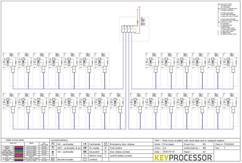
7.2.1.2       Wiring requirements ...................................................................................25
7.2.2         Clock- data / Wiegand card reader ...............................................................25
7.2.2.1       Connecting the card reader ..........................................................................26
7.2.2.2       Wiring requirements ...................................................................................26
7.3           Bus configuration with card reader ...............................................................26
7.3.1         Pluto – Orion as starting point of kpBus ........................................................27
7.3.1.1       Connection of kpBus ...................................................................................28
7.3.2         Polyx as communication starting point ..........................................................29
7.3.2.1       Connection of kpBus ...................................................................................30
7.3.3         Connection via an adapter board ..................................................................30
7.3.3.1       Wiring requirements ...................................................................................30
7.4           kpSensor bus connection .............................................................................31
7.4.1         Wiring requirements ...................................................................................31
7.5           Default inputs and outputs ..........................................................................32
7.5.1         Monitored inputs (A1 – A6) ..........................................................................32
8          Orion as replacement for the Orbit reader .........................................................34
8.1           Connecting to a network controller ...............................................................34
8.1.1         Controller  Orion PRT1 - RS422 ...............................................................35
8.1.2         Wiring requirements ...................................................................................35
8.1.3         Default inputs and outputs ..........................................................................36
9          Pluto-Orion as replacement for the iPU-8 ...........................................................37
10         Diagnostics ....................................................................................................38
10.1          Initiating Pluto diagnostics ...........................................................................38
10.2          Polyx/iPU-8: Connecting across the Console port ............................................39
10.2.1        Initiating iPU-8 diagnostics ..........................................................................39
10.2.2        Initiating Polyx diagnostics ..........................................................................42
10.2.2.1      Orion as functional replacement for the Orbit reader .......................................42
10.2.2.2      Multiple Orions on a single data line (bus) .....................................................44
11         How to ..........................................................................................................46
11.1          Installation Pluto ........................................................................................46
11.2          New Orion on existing Pluto .........................................................................47
11.3          New RS485 reader on existing Orion .............................................................47
11.4          New Orion on existing Polyx ........................................................................48
11.5          Replace Polyx for Pluto and Orion .................................................................48
11.6          Replace Polyx (2x kpBus) for Pluto and two Orions .........................................49
11.7          Replace iPU-8 for a Pluto with four Orions .....................................................50
11.8          Pluto - Make factory default .........................................................................50
11.9          Pluto – Removing iProtect data ....................................................................51
12         Technical data................................................................................................52
12.1          Pluto .........................................................................................................52
12.2          Orion ........................................................................................................53
13         Declaration of conformity ................................................................................55
13.1          Pluto .........................................................................................................55
13.2          Orion controller ..........................................................................................56
14         Technical drawings .........................................................................................57
14.1          72000310 – Pluto/Orion setup with network connection and power supply.........57
14.2          72000206 - Pluto/Orion with Sirius RS485 and IO ..........................................58
14.3          72000202 - Pluto/Orion with Sirius clock-data/Wiegand and I-O ......................59
14.4          72000207 – Pluto/Orion with IO, Sirius Clock-data/Wiegand and Orbits ............60
14.5          72000304 - Pluto with power supply and USB-RS232 converter .......................61
14.6          72000203 – Pluto/Orion with kpBus ..............................................................62
14.7          72000204 - Orion with kpSensor bus ............................................................63
14.8          72000602 - Pluto Orion stacked with 8x RS485 Sirius-i readers .......................64
14.9          72000602 - Pluto Orion with clock-data or Wiegand readers ............................65
14.10         72000602 - Pluto Orion with RS485 readers & kpBus combi .............................66
14.11         72000504 - Polyx with kpBus .......................................................................67

3
4

List of images
Figure 1: Mounting controller .......................................................................................... 7
Figure 2: Tamper contact ............................................................................................... 8
Figure 3: Stacking connector .......................................................................................... 8
Figure 4: Front side Pluto ............................................................................................. 10
Figure 5: Rear side Pluto ............................................................................................. 10
Figure 6: Example of connection with Orions ................................................................... 12
Figure 7: Pluto serial connection .................................................................................... 13
Figure 8: Orion connections front .................................................................................. 18
Figure 9: Orion connections rear ................................................................................... 18
Figure 10: Imprint Orion rear ........................................................................................ 19
Figure 11: Imprint Orion front ....................................................................................... 19
Figure 12: Inserting the SD card ................................................................................... 21
Figure 13: Connecting with Orions with Pluto .................................................................. 23
Figuur 14a: Connecting with Orions kpBus ...................................................................... 23
Figure 15: Polyx with RS485 card reader ........................................................................ 24
Figure 16: Pluto with RS485 card reader ........................................................................ 24
Figure 17: Orion with Clock- data / Wiegand reader ......................................................... 25
Figure 18: Pluto/Orion - kpBus ...................................................................................... 27
Figure 19: Pluto/Orion - kpBus with Clock- data / Wiegand and RS485 reader ..................... 28
Figure 20: Polyx - kpBus .............................................................................................. 29
Figure 21: Polyx - kpBus with Clock- data / Wiegand and RS485 reader ............................. 29
Figure 22: Orion - kpSensor connection.......................................................................... 31
Figure 23: iPU-8 with Orions ......................................................................................... 34
Figure 24: iPU-8 with Orbits.......................................................................................... 34
Figure 25: Polyx with Orbits .......................................................................................... 35
Figure 26: Polyx with Orions ......................................................................................... 35
Figure 27: Pluto and Orion with 2 Orbits ......................................................................... 37
Figuur 28: iPU-8 with 2 Orbits ....................................................................................... 37

5
1 Introduction
This instruction manual covers the entire range of Keyprocessor modular controllers.
One or more software versions are specified in every module-related chapter. These versions
are important when it comes to support for the product.

6

2 General
2.1 Mounting
Mount on a 35mm DIN rail type O profile.
Mount the rail to a wall or inside a secure casing.
Place the modular controller against the rail and click it into place.
Figure 1: Mounting controller
Mounting the modular controller onto the rail.
NOTE For every modular controller, note the location, serial number and/or MAC address
of the device. This information can be found on top of the device, just below the
LED.
7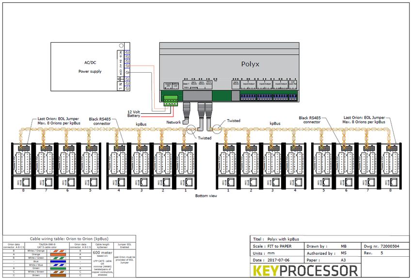
2.2            Power supply connection and tamper contact
The controller requires a power feed. For this purpose, use an orange four-pole power terminal
or the stacking connector.

The tamper contact T must be connected to the – GND terminal.
                          SW-1

    ─
    T
                                                         Figure 2: Tamper contact

              Connector D                           The Pluto can be connected to a 12VDC or 24VDC
    Symbol   Description                            power supply.
      ⏚      Earth ground                           Higher input power results in lower power
      ─      GND (digital ground)                   consumption and ensures cost-efficient wiring
      +      12V – 24VDC                            requirements as smaller-diameter conductors are
      T      Tamper contact                         needed.
                                                    The power supply must conform to SELV directives.

2.3            Stacking connector
The modular controller is fitted with a stacking connector terminal on either side.
This connector links together both the power and the communication feeds between the modular
controllers. Sections 4.1 and 7.1 specify specific conditions for the use of this connector.

Operation:
The supplied stacking connector must be inserted according to the below image:

Orion side (short pins)

                                                    Pluto side (long pins)

                                 Figure 3: Stacking connector

8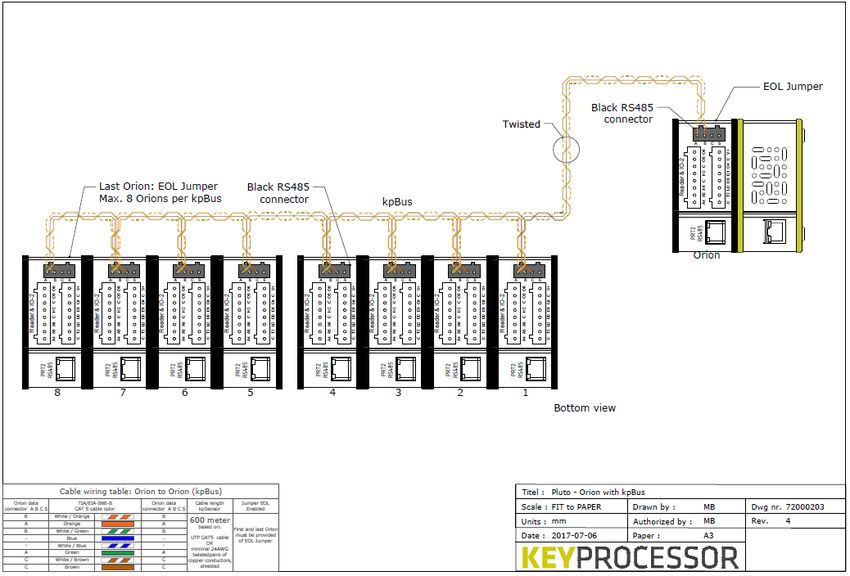
3 Pluto
The Pluto is an extremely powerful controller with a multicore processor, a secure bootloader
(u-boot), and a linaro release with Linux kernel.

3.1           Applications
Depending on the situation, the Pluto can be used in a range of different ways.
The Pluto can be used if:
   • More flexibility is required
   • More redundancy is required
   • End-to-End security is required
   • Maximum security is required

3.2           Required software versions
In order to guarantee optimum performance, the following software versions are required:

    Version          Supported                                              iProtect Support

    Linux            ≥ Ubuntu 16.04                                         ≥ 8.04
    Rootfs           ≥ V4.22

9
3.3            Connections
                 C                                                               C

                                              B                                                   G
D

E

        A                    Figure 5: Rear side Pluto
                                                             F                    Figure 4: Front side Pluto

 Port       Description
   A        USB 2.0 port (x2)
   B        Stacking connector for Orions
   C        Status LED
   D        Power input
   E        USB OTG console port
   F        Network port
   G        Stacking terminal (for future use)

3.4            Status LED
With the RGB LED, the current mode of the Pluto can be determined at a single glance. The
Pluto’s status LED is described in the table below:
                                Port C

 Colour of the LED         Description
 Blue                      No connection
 Red                       No active Node manager
 Yellow                    Line active, Node(s) inactive (0%)
 Green                     Line and Node(s) active (100%)

3.5            Support in offline situation
When a Pluto no longer has a network connection with the server, an offline situation arises. In
order to guarantee autonomous operation, local data storage is necessary (including cards with
valid access rights). And in this offline situation, the events of inputs, (lock control)outputs and
cards may not be lost.

10
The maximum numbers are described in the table below: Pluto storage (FIFO) Nr. Description: Maximum per Pluto: 1 Cards with valid access rights 50.000 2 Events 50.000 11
4 Pluto connection options
The Pluto’s various connection options are described in this section.

4.1           Connecting with Orion
The right-hand terminal on the Pluto is not designed for use with a controller. Connecting a
modular controller (e.g. an Orion) to the LED side of the Pluto will not damage it, however,
communication with the device will not be possible.

                                 4x Stacking connector

              Orion-4      Orion-3      Orion-2   Orion-1      Pluto

              PRT2   L    PRT2   L     PRT2   L   PRT2   L          N

                                     Front                         Figure 6: Example of connection with Orions

When it comes to connection, the following conditions are important:
•  when inserting stacking connectors, always ensure the power is off
•  depending on the power feed being used (at least 75W), a maximum of four Orions can be
   interconnected to one another to the left of the Pluto, using the stacking connector (see
   Figure 3: Stacking connector)
•  if the stacking connector is used to supply the Orions with power and the door controllers
   collectively draw more power than 50W, the C (GND) on the last Orion, beside the High-
   Power output, must be separately wired to the power supply (-).

12
4.2 Serial connection (RS-232)
If a connection in series is preferred, a
USB-to-RS232 converter (recommended
by Keyprocessor, part number 503-1805)
must be used. Only one USB-to-RS-232
converter can be used per Pluto (See
chapter 14.5).
USB
Rear
RS-232
Figure 7: Pluto serial connection
135 Maintenance page Pluto
The Pluto has its own maintenance page. This maintenance page includes assistance with
network settings as well as system testing.
The Pluto’s default IP address is 192.168.1.195. In order to access the maintenance page, enter
the following into your browser: https://192.168.1.195
When the page opens, it will display a login screen. Once the right username and corresponding
password have been entered, the system status page will be displayed.
Default login:
• Username: controller
• Password: Pluto
The following page is displayed:
NOTE When iProtect connects to the Pluto, the default password will expire. The new login
password will be displayed in the iProtect line in the admin page.
5.1 Network settings
Network settings, e.g. IP address settings, can be manually configured.
• To do so, click on the ‘Network settings’ button and enter the desired settings into
the ‘device’ field.
14Once saved, the new settings will take immediate effect and the Pluto will only be accessible using the new IP address. 15
6 Orion

6.1           Applications
The Orion can be used for a range of applications. Extra features include:
   • End-to-End security (RS485 card reader)
   • RS485 communication bus (kpBus)
   • Replacement of existing Orbit reader
   • Additional functionality

6.2           Required software versions
In order to guarantee optimum performance, the following software versions are required:

 Version                             Supported                                        iProtect
                                                                                      version
 Orion      Applicatie: 1.1.26       Functional replacement for Orbit reader;         ≥ 8.03
 firmware   Bootloader 2.0.1         kpBus communication
            Applicatie: ≥ 1.4.37     Functional replacement for Orbit reader;         ≥ 8.04
            Bootloader ≥ 2.3.0.14    kpBus communication; calamity card (SD-
                                     card); Sirius Pincode based on Clock- data/
                                     Wiegand protocol; NO/NC-output behavior;
                                     provisioning; connection to Pluto

6.3           Functions and support
Depending on the desired application of the Orion, a range of functions are available. Below is a
list of functions.

6.3.1           Orion – connected to the Pluto

 Type of controller                   Pluto
 connected:
                                      Number        Connection
 Digital input                        2             T1, T2
 Digital output                       8             O1, O2, O3, O4, O5, O6, H1 and H2
 Monitored inputs (ADC)               6             A1, A2, A3, A4, A5, A6
 Orion override input                 1             T
 Wiegand/ABA card reader              2*            LD, D0, D1, C and V+
 kpSensor                             2**           C, S
 Location buzzer                      Yes
 Status LED                           Yes
 MicroSD card                         -
 RJ45 – PRT1                          RS485 card reader or Orbit
 RJ45 – PRT2                          kpBus communication or RS485 card reader or Orbit
 Indoor temperature sensor            Yes
 Power supply measurement             Yes

16
Power measurement reader Yes
Power consumption readers Yes
H1 and H2 overload detection Yes
6.3.2 Orion – RS485 bus communication (kpBus)
Type of controller Polyx, Pluto
connected:
Number Connection
Digital input 2 T1, T2
Digital output 8 O1, O2, O3, O4, O5, O6, H1 and H2
Monitored inputs (ADC) 6 A1, A2, A3, A4, A5, A6
Orion override input 1 T
Wiegand/ABA card reader 2* LD, D0, D1, C and V+
kpSensor 2** C, S
Location buzzer Yes
Status LED Yes
MicroSD card For emergency card use
RJ45 – PRT2 kpBus communication
Indoor temperature sensor Yes
Power supply measurement Yes
Power measurement reader Yes
Power consumption readers Yes
H1 and H2 overload detection Yes
6.3.3 Orion – functional replacement for the Orbit
reader
Type of controller connected: iPU-8, Polyx or Pluto
Number Connection
Digital input 8 A1, A2, A3, A4, A5 A6, T1, T2
Digital output 4 H1, H2, O2, O5
Wiegand/ABA card reader 2 LD, D0, D1, C and V+
Status LED Yes
RJ45 – PRT1 RS422 communication with controller
Indoor temperature sensor Internal only
Power supply measurement Internal only
Power measurement reader Internal only
Power consumption readers Internal only
H1 and H2 overload detection Internal only
* D0 and D1 are shared inputs. If no card reader is used, D0 and D1 can be used as digital
inputs.
** Only the combined Temperature & Humidity sensor supplied by Keyprocessor is supported.
176.4 Connections
The connection ports on the Orion are described in this section. Options depend on the
application and the method of connection.
E F G G F E
D H I H
H H
C J
B K
PRT2
PRT1
Figure 8: Orion
Figure 9: Orion connections front
connections rear
A L
Port Description
A PRT1
B Reader 1
C IO 1
D Power input
E Status LED
F MicroSD slot
G End of line jumper
H Stacking connector
I RS485 and kpSensor bus
J Reader 2
K IO 2
L PRT2
186.4.1 Description imprint Orion
The connection ports and imprints on the Orion are illustrated below:
C
K Figure 10: Imprint Orion
rear
D B A
L
Figure 11: Imprint Orion
front
L J I
Reader & IO-1
Connector: A Description
PRT1 Communication port
Connector: B Description Connector: C Description
C GND (digital ground) A1 Monitored input 1
T1 Digital input (Override card reader) A2 Monitored input 2
LD Card reader LED operation A3 Monitored input 3
D0 DO/Data or Digital input C Digital ground
D1 D1/Clock or Digital input H1 High Power output 1
O1 Digital output 1 C Digital ground
C GND (digital ground) O2 Digital output 2
+V Power feed card reader O3 Digital output 3
Connector: D Description
⏚ Earth ground
- GND (digital ground)
+ Orion power input (12-24VDC)
T Tamper input
19Connector: I Description
A kpBus (RS485)
B kpBus (RS485)
C GND (digital ground), for data use only.
S kpSensor
Reader & IO-2
Connector: J Description Connector: K Description
C GND (digital ground) A4 Monitored input 4
T2 Digital input (Override card reader) A5 Monitored input 5
LD Card reader LED operation A6 Monitored input 6
D0 DO/Data or Digital input C GND (digital ground)
D1 D1/Clock or Digital input H2 High Power output 2
O4 Digital output 4 C GND (digital ground)
C GND (digital ground) O5 Digital output 5
+V Power feed card reader O6 Digital output 6
Connector: L Description
PRT2 Communication port
NOTE the Orion must not be connected directly to the network. Doing so may result in
severe damage to the device, including loss of functions.
6.5 Status LED
With the RGB LED, the current mode of the Orion can be determined at a single glance. The
Orion’s status LED is described in the below table:
Port D
Colour of the LED Description
Light blue Bootloader : Connecting to iProtect
Blue Bootloader : Starting
Blue Bootloader : Programming firmware (Or violet)
Pink Bootloader : No valid application to start
Pink Application : Format SD card
Orange Application : Checking SD card (initialisation)
Green Application : Calamity mode
Red Application : When using no SD card, the LED will flash red if the
device cannot communicate with the network controller.
Red Application : If the LED displays a solid red light, the Orion has
detected a surge or short circuit. This also means that the Orion is
not communicating with the network controller.
Orange Application : If the LED displays a solid amber light, the Orion has
detected a surge or short circuit, but is nevertheless
communicating with the network controller.
Green Application : The LED will display a solid green light when the
Orion is communicating with the network controller and no input
or output anomalies are detected.
Green Application : If the location buzzer of the Orion is activated, the
green status LED will flash fast.
206.6 SD-card functionality
Additional functionality is available when using an SD card in the Orion. When there is no
communication (kpBus) with the network controller, the local operation of the access will be
guaranteed.
This functionality is available from:
• iProtect version 8.04 or higher
• Orion application version 1.4.37 or higher
• Orion bootloader version 2.3.0.14 or higher
6.6.1 Inserting the SD card
Part number: 501-1905
Figure 12: Inserting the SD card
1. Remove the power from the Orion before inserting the SD card.
2. The copper slots of the SD card must be facing inwards for inserting the SD card. The
card must be clicked without any pressure. See Figure 12.
Note! Inserting the SD card incorrectly could cause serious damage to the Orion
or SD card.
6.6.2 Calamity cards
Calamity cards are cards that need access to a door(s) when there is no communication with the
Network Controller (offline).
In an offline situation, the Orion will function fully independently. If a user has a calamity priority,
which is created within iProtect in the card dialog, there will be no noticeable issues for the user.
If the Orion communicates with the Network Controller, all events will be sent to iProtect.
6.6.3 Support in offline situation
The following features are supported during the Offline situation:
The following table shows the maximum numbers:
Storage SD-card
Nr. Description: Maximum per Orion:
1 Cards with valid access rights 4.000
2 Events 560.000
The following table shows all the events:
21Events
Nr. Description
1 Push button access
2 Push button no access
3 Card access
4 Card no access
5 Card no calamity card
6 Emergency door release activated
7 Emergency door release deactivated
The following table shows all the inputs:
Inputs
Nr. Connection: Description: Reader nr. Invert (NO/NC)
1 A1 Loop (enable) Reader 1 Yes
2 A2 Push button
3 T1 Emegency door release
4 A4 Loop (enable) Reader 2
5 A5 Push button
6 T2 Emegency door release
The following table shows all the outputs:
Outputs
Nr. Connection: Description: Reader nr. Invert (NO/NC)
1 H1 Door lock Reader 1 Yes
2 O1 Output
3 O2 Alarm
4 O3 Output
5 H2 Door lock Reader 2
6 O4 Output
7 O5 Alarm
8 O6 Output
The following table shows the reader:
Reader
Nr. Description: Protocol: Kaartdata Pincode
interpretation: function offline
1 Reader 1 Clock – data/ Wiegand Max. 1 Pincode
2 Reader 2 Clock – data/ Wiegand Max. 1 switched off
Note: It is possible to use combined input or output by a reader. Consider a door with a card
reader on both sides.
227 Orion connection options
The Orion’s various connection options are described in this chapter.
7.1 Connecting with Orion
When it comes to connection, the following conditions are important:
• When inserting stacking connectors, always ensure the power is off.
• Depending on the power feed being used (at least 24VDC – 75W), a maximum of four Orions
can be interconnected to one another by means of stacking connectors.
• If stacking connectors are used to supply the Orions with power and the door controllers
collectively draw more than 2A, the C (GND) on the last Orion, beside the High-Power output,
must be separately wired to the power supply (-).
• When connecting Orion(s) to a Pluto, the kpBus should not be connected externally. See
figure 13.
• When linking only Orions, the kpBus must be connected externally. See figure 13a.
Stacking connector (communication (USB) and power)
Orion-4 Orion-3 Orion-2 Orion-1
Pluto
PRT2 L PRT2 L PRT2 L PRT2 L N
Front
Figure 13: Connecting with Orions with Pluto
Stacking connector (power)
Orion-4 Orion-3 Orion-2 Orion-1
kpBUS
ABC ABC ABC ABC
PRT2 X
L PRT2 X
L PRT2 X
L PRT2 X
L
Figuur 14a: Connecting with Orions kpBus
Front
237.2 Connecting card reader
7.2.1 RS485 card reader
Choosing the option to connect RS485 card readers to the controller offers the following
advantages:
• ‘Key information’ from the card reader is transferred to the controller. The card reader
is always publicly accessible, while the controller is located in a secure and concealed
area. This means that the settings required for reading cards are located in the controller
instead of in the card reader.
• Communication between cards and the system can be secured by means of AES
encryption.
• When (the maximum of) four Orions are connected to a Pluto (see figure 13), a maximum
of eight RS485 card readers can be connected.
Orion Pluto
X
Polyx
PRT2 L N USB A PRT1
N D 1 2 3
Max. 4x Orion Front Rear Max. 4x Orion
RS485 RS485 RS485
Figure 16: Pluto with Figure 15: Polyx with
RS485 card reader RS485 card reader
7.2.1.1 Connection of RS485 card reader
PRT1(A)- 2(L) TIA/EIA-568-B Sirius i-serie
Nr. Description Wire color Sticker Description
1 B White/Orange 2 B
2 A Orange 1 A
3 B (Z) White/Green 2 B
4 12Vdc Blue Vcc Vcc
5 GND White/Blue GND GND
Figure T-
568B
6 A (Y) Green 1 A
7 GND White/Brown GND GND
8 GND Brown GND GND
247.2.1.2 Wiring requirements
The wiring required between the card reader and the Orion is listed below:
Cable Communication Remote Communication between
protocol
UTP ≥Cat5e RS485 120m Orion and Sirius i-series card reader
7.2.2 Clock- data / Wiegand card reader
In virtually all configurations, you have the option of connecting a Clock- data / Wiegand card
reader to either side of the Orion, except if an RS485 card reader is connected. It is not
possible to connect a second card reader to any one side of the Orion.
Orion Pluto
J B
USB PRT1
PRT2 N
Front Rear
Clock– data Clock– data
Wiegand Wiegand
Figure 17: Orion with Clock- data / Wiegand reader
257.2.2.1 Connecting the card reader
Orion reader & TIA/EIA-568-B Sirius i-serie
IO-1/2
Description Wire color Sticker Description
D0 White/orange 3 D0
- Orange - -
D1 White/green 4 D1
+V Blue Vcc Vcc
LED White/blue 5 LED
- Green - -
C White/brown GND GND
C Brown GND GND
7.2.2.2 Wiring requirements
The wiring required between the card reader and the Orion is listed below:
Cable Communication Remote Communication between
protocol
UTP ≥Cat5e Wiegand 120m Orion and Sirius i-series card reader
Clock/Data 50m
7.3 Bus configuration with card reader
If an Orion is connected in bus configuration (kpBus):
• communication must be established via the black 4-pole screw connector
• a maximum of eight Orions per kpBus applies
• the maximum cable length is 600m
• the power feed does not run across the kpBus
• every Orion must be provided with its own power feed
• the serial number and location of every Orion must be noted (see section 2.1)
267.3.1 Pluto – Orion as starting point of kpBus
If the Orion is linked to the Pluto and the relevant Orion is used as the beginning of a kpBus,
then:
• The Orion connected to the Pluto is not included in the number of Orions in the kpBus.
• A maximum of one kpBus can be established per Orion. So, if four Orions are stacked with
a Pluto, four kpBuses can be established (see figure 13).
• A RS485 card reader cannot be connected to PRT2.
• A clock data / Wiegand card reader can be connected on both sides of the Orion.
• if there is no clock data/ Wiegand reader is connected to the "Reader & IO 1" side, a
RS485 card reader can be connected to PRT1, see figure 18.
EOL
Jumper
Orion Pluto
kpBus I
ABC
Max. 32x Orions
Max. 32x card readers
PRT2 X N
I I I
Max 8
ABC ABC ABC
The last Orion must
have an EOL Jumper.
1 2 3
PRT2 X PRT2 X PRT2 X
Figure 18: Pluto/Orion - kpBus
27kpBus Orion Pluto
I
ABC
Max. 32x Orions
Max. 32x card readers
PRT1
PRT2 X N
I I I
Max. 8
ABC ABC ABC
1 2 3
PRT2 X PRT2 X PRT2 X
Figure 19: Pluto/Orion - kpBus with Clock- data / Wiegand and RS485 reader
7.3.1.1 Connection of kpBus
ABCS
Orion (I) TIA/EIA-568-B Orion (I)
I
ABCS Colour of the cable ABCS
B White/orange B
A Orange A
B White/green B
- Blue -
- White/blue -
A Green A
PRT2 X C White/brown C
C Brown C
Illustration of
kpBus
connection
NOTE If the kpBus begins with an Orion, the start and the end of the kpBus must have
an EOL jumper, see Figure 18: Pluto/Orion - kpBus.
287.3.2 Polyx as communication starting point
Polyx
Max. 16x Orions
Max. 32x card readers
N D 1 2 3
kpBus-1 Polyx the starting point of kpBus
at all times!
I I ABC I
Max. 8
ABC ABC
The last Orion must
have an EOL Jumper.
1 2 3
PRT2 X PRT2 X PRT2 X
Figure 20: Polyx - kpBus
Polyx
max. 16x Orions
max. 32x card readers
N D 1 2 3
kpBus-1
I I I
Max. 8
1 2 3
J J J
PRT2 X PRT2 X PRT2 X
Figure 21: Polyx - kpBus with Clock- data / Wiegand and RS485 reader
297.3.2.1 Connection of kpBus
When using shielded cable, one end of the cable’s metal sheath must be attached to the earth
ground connection ⏚ in the system cabinet.
Polyx TIA/EIA-568-B Orion
I ABCS
PRT1– 2 (I)
ABCS
Nr. Description Wire color
1 RxA White/orange B
2 RxB Orange A
3 TxZ White/green B
Afbeelding
T-568B 4 +12Vdc Blue -
5 Orbit sense White/blue -
PRT2 X
6 TxY Green A
Illustration
7 GND White/brown C of kpBus
8 GND Brown C connection
NOTE the Polyx is always the starting point of a kpBus. Add an EOL jumper to the end
of the kpBus, see Figure 20: Polyx - kpBus.
7.3.3 Connection via an adapter board
If no direct UTP connection between the network controller and the Orion is possible, an adapter
board can be used.
Possible reasons for the use of an adapter board include:
• The Orion and the network controller are mounted in different buildings, so the connection
cable exits the building
• The connection cable is not – or is not guaranteed to be – a (≥Cat5e) UTP cable (e.g. if an
existing connection cable is being reused)
• Surge protection is required
The adapter board along with the network controller are connected using standard UTP ≥Cat5e
cable (plug-in connection). For more information, please refer to the adapter board manual.
7.3.3.1 Wiring requirements
Recommended cable for communication bus between network controller and Orion(s):
Cable Communication Total kpBus distance (metres)
protocol
UTP ≥Cat5e RS485 600
Twisted pairs of 24AWG (at least)
copper conductors, shielded
307.4 kpSensor bus connection
The Orion is fitted with a kpSensor bus port. This allows the Orion to measure, for instance, the
temperature and humidity in a certain area.
Connector I TIA/EIA-568-B 571-1013 Sensor
Colour of the cable
Wire color Nr. Description
- White/orange 1 GND
- Orange 2 -
V+ (reader) White/green 3 12VDC
S Blue 4 kpSensor
C (reader) White/blue 5 GND
- Green 6 - Figure
T-568B
- White/brown 7 -
- Brown 8 -
I 571-1013 571-1013
ABCS
S
V+ V+
C C (GND)
Figure 22: Orion - kpSensor connection
Illustration
of kpBus
connection
PRT2
NOTE the Orion only supports one type of kpSensor. It is the combined temperature
and humidity sensor (kpSensor: 571-1013).
7.4.1 Wiring requirements
The required wiring between the kpSensor and the Orion is listed below:
Connector I
Symb Description Bus length Number of kpSensors Type of cable
ol
C GND (reader) 30m 2 UTP
S kpSensor
V+ 12VDC (reader)
317.5 Default inputs and outputs
The Orion’s inputs and outputs are described below.
Reader & IO-1:
Symbol Description iProtect default
T1 Digital input Door in latch mode
D0 D0 / Data or Digital input*
D1 D1 / Clock or Digital
input*
O1 Digital output
A1 Monitored input 1 Loop / Enable
A2 Monitored input 2 Button
A3 Monitored input 3 Door mode
H1 High Power output Door operation
O2 Digital output Alarm
O3 Digital output
Reader & IO-2:
Symbol Description iProtect default
T2 Digital input Door in latch mode
D0 D0 / Data or Digital input*
D1 D1 / Clock or Digital input*
O4 Digital output
A4 Monitored input 4 Loop / Enable
A5 Monitored input 5* Button
A6 Monitored input 6* Door mode
H2 High Power output Door operation
O5 Digital output Alarm
O6 Digital output
7.5.1 Monitored inputs (A1 – A6)
When using monitored inputs (ADC), a certain state of the input can be determined by one or
more resistance values. This includes a detection of tampering or intrusion detector sabotage.
Default input types are:
- NO - Normally open
- NC - Normally closed
- Blocked
- EOL (End Of Line)*
- DEOL (Dual End Of Line)*
- DEOL inverted*
- TEOL (Triple End Of Line)*
- TEOL inverted*
* Recommended resistor values: EOL: 4k7 or 5k6 and Masking 22K
32Resistor values
NC NO EOL DEOL DEOL TEOL TEOL
Sabotage inverted inverted
0 – 699 0 – 699 0 – 699 0 – 699 0 – 699 0 – 699 0 – 699
Idle Active Sab. Closed Sab. Closed Sab. Closed Sab. Closed Sab. Closed
700 – 60K 700 – 60K 700 – 6999 700 – 6999 700 – 6999 700 – 6999 700 – 6999
Active Idle Idle Idle Active Idle Active
7K – 60K 7K – 14999 7K – 14999 7K – 14999 7K – 14999
Sab. Open Active Idle Active Idle
15k – 60K 15k – 60K 15k – 40K 15k – 40K
Sab. Open Sab. Open Masking Masking
40k – 60K 40k – 60K
Sab. Open Sab. Open
Input GND Input GND Input GND Input GND Input GND Input GND Input GND
Contact Contact Contact Alarm Alarm Anti Mask
Anti Mask
Contact Contact Contact Contact
Alarm Alarm
NC NO EOL DEOL DEOL Contact Contact
Sabotage inverted
TEOL TEOL
inverted
338 Orion as replacement for the Orbit reader
As is the case with the Orbit reader, the Orion also supports Clock- Data / Wiegand card readers.
In order to use the Orion as a functional replacement for the Orbit reader:
• The Orion must be configured within iProtect™ as node type “Orbit(RS422)”. Different
iProtect™ software versions do not have to be taken into account here.
• The Orion must be connected to the network across PRT1.
8.1 Connecting to a network controller
The Orion is functionally compatible with the Orbit reader. All Orbit reader inputs and outputs
are available on the Orion. However, the inputs and outputs are different. This must be taken
into account (See chapter 8.1.3).
Below is an installation illustration. It is possible to combine existing Orbit readers and Orions:
iPU-8 iPU-8
N 1 2 3 4 5 6 7 8 N 1 2 3 4 5 6 7 8
Max 8 Max. 8
RS422 RS422 Orion
Orbit 1
Orbit 2 PRT1 A
PRT1 A
Clock- Data / Clock- Data /
Wiegand Wiegand
Figure 24: iPU-8 with Orbits Figure 23: iPU-8 with Orions
34Polyx Polyx
N D 1 2 3 N D 1 2 3
Max. 2 Max. 2
RS422 RS42 Orion
2
Orbit 1
Orbit 2 PRT1 A
PRT1 A
Clock- Data /
Clock- Data /
Wiegand
Wiegand
Figure 25: Polyx with Orbits Figure 26: Polyx with Orions
8.1.1 Controller Orion PRT1 - RS422
iPU-8 PRT 1 – 8 TIA/EIA-568-B Orion (A)
OF PRT1
Polyx PRT1– 2
Nr. Description Wire color Nr. Description
1 RxA White/orange 1 B
2 RxB Orange 2 A
3 TxZ White/green 3 Z
4 +12Vdc Blue 4 12Vdc
Figure 5 Orbit sense White/blue 5 GND
T-568B
6 TxY Green 6 Y
7 GND White/brown 7 GND
8 GND Brown 8 GND
8.1.2 Wiring requirements
The cable recommended for use between the Orion and the network controller is listed below:
Cable Communication Remote Communication between
protocol
UTP/STP Cat≥3 RS422 1200m Network controller and Orion
358.1.3 Default inputs and outputs
When replacing an Orbit reader with an Orion, the below table can be used:
Orbit 2 Description of Orion iProtect™
Reader 1 connection Reader & IO-1 default
+5V 200mA MAX Reader voltage +V
GND GND (digital ground) C
D1 / CLK D1 / Clock D1
D0 / DAT D0 / Data D0
LED LED LD
⏚ Earth ground ⏚
Inputs 1 Inputs 1 Input/Output
IN0 Digital input A1 Loop
COM 0+1 GND (digital ground) C C
IN1 Digital input A2 Button
IN2 Digital input A3 Door mode
COM 2+3 GND (digital ground) C
IN3 Digital input T1 Door in latch mode
Outputs 1 Outputs 1
0 Digital output H1 Door operation
GND GND (digital ground) C
1 Digital output O2 Alarm
Orbit 2 Description of Orion iProtect™
Reader 2 connection Reader & IO-2 default
+5V 200mA MAX Reader voltage +V
GND GND (digital ground) C
D1 / CLK D1 / Clock D1
D0 / DAT D0 / Data D0
LED LED LD
⏚ Earth ground ⏚
Inputs 2 Inputs 2 Input/Output
IN0 Digital input A4 Loop
COM 0+1 GND (digital ground) C C
IN1 Digital input A5 Button
IN2 Digital input A6 Door mode
COM 2+3 GND (digital ground) C
IN3 Digital input T2 Door in latch
mode
Outputs 2 Outputs 2
0 Door Output H2 Door operation
GND GND (digital ground) C
1 Alarm output O5 Alarm
369 Pluto-Orion as replacement for the iPU-8
A Pluto in combination with the Orion can serve as a functional replacement unit for the Stellar
or ipU-8 Network Controller.
When an existing iPU-8 with 8 Orbits installation needs to be replaced, a Pluto with 4 stacked
Orions will suffice. Each Orion can be linked with maximal two Orbits. The type of Orbit is in this
case not relevant (Orbit-1, Orbit-2 or Obit-IO).
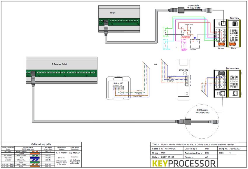
NOTE The existing UTP cabling of the Orbit is connected to the S2M cable. This must be
connected to the Orion. The cable length between iPU-8 and Orbit or between
Orion and Orbit remains unchanged.
In the picture below there is an example of replacing an iPU-8 for a Pluto and Orion:
iPU-8 Orbit-2
N 1 2 3 4 5 6 7 8
Max 8 Clock- Data /
Wiegand
S2M cable to PRT1
Orbit-1 Orion Pluto
Orbit-2
X
Clock- Data /
Wiegand
PRT2 N
Figuur 28: iPU-8 with 2 Orbits
Front side
S2M cable to PRT2
Orbit-1
Clock- Data /
Wiegand
Figure 27: Pluto and Orion with 2 Orbits
3710 Diagnostics
The Orion can be fully tested before communicating with iProtect ™ through a diagnostic
program on the Network Controller.
10.1 Initiating Pluto diagnostics
NOTE System diagnostics are only possible if there is no communication between the Pluto and
iProtect™.
Navigate to the Pluto’s IP address and perform the following steps:
• Click on the ‘Hardware’ button and activate diagnostics.
• Reader manager: The connected RS485 card readers will automatically be retrieved and
a (scroll-down) list will appear.
• Node manager: The connected Orions will automatically be retrieved and a (scroll-down)
list will appear.
• Select the Orion in question according to its serial number
• All inputs will be displayed
• All outputs will be displayed by selecting an output, it can also be switched
• The on-board sensors will be displayed
• When an access card is presented to a reader, the card number will be displayed
3810.2 Polyx/iPU-8: Connecting across the Console
port
System diagnostics can be carried out with the help of a PC / laptop.
For the purpose of diagnostics, every Controller has a diagnostics menu.
All that is required to do this is a series connection between the Controller and the PC or laptop.
However, “Terminal software” must be used.
A range of software, such as Teraterm (or hyperterminal) can emulate a VT100 terminal on a
PC. Such software must therefore be in place or must promptly be installed.
• Connect the PC to the Console port of the Polyx. To do this, use the adapter listed below
(available from Keyprocessor BV).
• Run the terminal software and establish a connection using the following settings:
• Select the COM port for the connected controller.
• If an iPU-8 controller is used:
o Set the baud rate to “9600”, Data to “8 bit”, Stop to “1 bit”, Parity to “None” and
Hardware control to “None”
• If a Polyx controller is used:
o Set the baud rate to “115200”, Data to “8 bit”, Stop to “1 bit”, Parity to “None”
and Hardware control to “None”
10.2.1 Initiating iPU-8 diagnostics
• iPU-8 diagnostics can be accessed by pressing on any key when the following text is
displayed: Hit any key within 5s to run diagnostics
The main menu will appear, containing the following options
--- iPU-8 diagnostics V1.00 ---
1) Environment settings
2) Test serial ports (loopback)
3 Test Profi-device communications
4) Test Profi-device functionality
5) Show board revision and test diag LEDs & inputs
6) Test Power
7) Test EEPROM
8) Test RTC
9) Test Watchdog
q) Start application
r) Restart system
Enter menu option:
Screen 1: iPU-8 diagnostics main menu
When it comes to testing the Orion, only options 2 and 3 apply for use by the installer.
39Option 3: Profibus communication test
If option 3 - Test Profi device communications - is selected from the main menu of the iPU-8
Diagnostics software, the Profibus DP communication test screen will appear. Here, it is
possible to specify per port whether a Profibus device is connected and, if so, which slave it is.
Communication mode indicates whether communication has been established
(connected/disconnected). The identification number of the relevant device is displayed, along
with the hardware and software version numbers.
--- Profibus DP communication test ---
Comm. status Ident no. Hw/Sw version
------------ --------- ---------------
1) Profi slave 1 Connected 0xfffd IE-ORBRD2 V1.03
2) Profi slave 1 Connected 0xfffd KP-ORION V1.00
3) Profi slave 1 Connected 0xfffd IE-ORBRD2 V1.03
4) No profi-dev. Disconnected
5) No profi-dev. Disconnected
6) No profi-dev. Disconnected
7) No profi-dev. Disconnected
8) No profi-dev. Disconnected
1..8) : toggle device type S) : toggle start/stop Q) : Quit
Screen 2: Profibus communication test
If option 4 - Test Profi device functionality - is selected from the main menu of the iPU-8
Diagnostics software, correct performance of the connected devices can be tested. Firstly, the
port to which the test device is connected must be entered. This will bring up a list of the
various types of devices that may be connected.
40In the menu, an Orion corresponds to an Orbit-2 (Profi DP reader*2).
In the following example, option 2, Profi DP reader-2, has been selected:
--- Device functionality test ---
Enter the device to test 1..8) : 1
1) Profi DP reader-1
2) Profi DP reader-2
3) Profi DP io
Enter the device type : Profi DP reader-2
Enter slave no. 1)..4) (CR=1): 1
MT interface or Wiegand interface [M/W] for reader 1 ? : M
MT interface or Wiegand interface [M/W] for reader 2 ? : M
Continue [Y] ? :
Screen 3: Device functionality test
On this screen, entry of the slave number is requested. This value must be set to 1.
The right type of interface must be chosen for both reader inputs.
Once all entries have been confirmed as correct, the options and mode relevant to the selected
device are displayed:
--- Profibus DP orbit reader test, no. 2 ---
Label Orion
1) Output R1-0: On : (H1)
2) Output R1-1: On : (O2)
3) Output R2-0: On : (H2)
4) Output R2-1: On : (O5)
5) RdrLED R1
6) RdrLED R2
Input R1-0: Off 128 : (A1)
Input R1-1: Off 128 : (A2)
Input R1-2: Off 128 : (A3)
Input R1-3: Off 128 : (T1)
Input R2-0: Off 128 : (A4)
Input R2-1: Off 128 : (A5)
Input R2-2: Off 128 : (A6)
Input R2-3: Off 128 : (T2)
Reader : R1: 29748424 08
State : Data exch.
1)... : toggle output state or flash reader LED S) : stop
Screen 4: Device functionality test, options and mode of an Orion as an Orbit reader
On the above screen, the inputs and outputs can be tested. The outputs can be activated or
deactivated using keys 1 to 4. Keys 5 or 6 can be used to test the card reader LEDs (rapidly
press 5 times to turn on or off).
When a card is presented to one of the card readers, the relevant card information will be
displayed after the Reader field. Here, R1 indicates that card reader 1 has read a card. R2
indicates that card reader 2 has read a card. The number after the scanned card number (08 in
this instance) indicates the number of characters in the card number.
4110.2.2 Initiating Polyx diagnostics
Depending on the function and the method of connection (PRT1 or PRT2 from Orion), it is possible
to use certain sections of the diagnostics menu. Diagnostics for both connection methods are
described in the below paragraphs.
10.2.2.1 Orion as functional replacement for the Orbit reader
• iPU-8 diagnostics can be accessed by pressing on any key when the following text is
displayed: Hit any key within 5s to run diagnostics
The main menu will appear, containing the following options
Polyx Diags version V3.0.5
1) Environment settings
2) Test onboard I/O
3) Test RS422 devices (loopback)
4) Test profi-device Communications
5) Test profi-device functionality
6) Test Orion-device Communications
7) Test Orion-device functionality
8) Clean nodemgr
9) Test Watchdog
a) Clean system
b) Clean /etc/rc.d/* to /etc/save.d/*
v) Version
p) Polyx menu
q) Start application
r) Restart system
Enter menu option:
Screen 1: Polyx diagnostics main menu
When it comes to testing the Orion, only options 4 and 5 apply for use by the installer.
Option 4: Profibus communication test
If option 4 - Test Profi device communications - is selected from the main menu of the Polyx
Diagnostics software, the Profibus DP communication test screen will appear. Here, it is
possible to specify per port whether a Profibus device is connected and, if so, which slave it is.
Communication mode indicates whether communication has been established
(connected/disconnected). The identification number of the relevant device is displayed, along
with the hardware and software version numbers.
--- Profibus DP communication test ---
Comm. status Ident no. Hw/Sw version
------------ --------- ---------------
1) Profi slave 1 Connected 0xfffd IE-ORBRD2 V1.03
2) Profi slave 1 Connected 0xfffd KP-ORION V1.00
1..8) : toggle device type S) : toggle start/stop Q) : Quit
Screen 2: Profibus communication test
If option 5 - Test Profi device functionality - is selected from the main menu of the Polyx
Diagnostics software, correct performance of the connected devices can be tested. Firstly, the
port to which the test device is connected must be entered. This will bring up a list of the
various types of devices that may be connected. In the menu, an Orion corresponds to an
Orbit-2 (Profi DP reader*2).
42In the following example, option 2, Profi DP reader-2, has been selected:
--- Device functionality test ---
Enter the device to test 1..8) : 1
1) Profi DP reader-1
2) Profi DP reader-2
3) Profi DP io
Enter the device type : Profi DP reader-2
Enter slave no. 1)..4) (CR=1) : 1
MT interface or Wiegand interface [M/W] for reader 1 ? : M
MT interface or Wiegand interface [M/W] for reader 2 ? : M
Continue [Y] ? :
Screen 3: Device functionality test
On this screen, entry of the slave number is requested. This value must be set to 1.
The right type of interface must be chosen for both reader inputs.
Once all entries have been confirmed as correct, the options and mode relevant to the selected
device are displayed:
--- Profibus DP orbit reader test, no. 1 ---
1) Output R1-0: On : (H1)
2) Output R1-1: On : (O2)
3) Output R2-0: On : (H2)
4) Output R2-1: On : (O5)
5) RdrLED R1
6) RdrLED R2
Input R1-0: Off 128 : (A1)
Input R1-1: Off 128 : (A2)
Input R1-2: Off 128 : (A3)
Input R1-3: Off 128 : (T1)
Input R2-0: Off 128 : (A4)
Input R2-1: Off 128 : (A5)
Input R2-2: Off 128 : (A6)
Input R2-3: Off 128 : (T2)
Reader : R1: 29748424 08
State : Data exch.
1)... : toggle output state or flash reader LED S) : stop
Screen 4: Device functionality test, options and mode of an Orion as an Orbit reader
On the above screen, the inputs and outputs can be tested. The outputs can be activated or
deactivated using keys 1 to 4. Keys 5 or 6 can be used to test the card reader LEDs (rapidly
press 5 times to turn on or off).
When a card is presented to one of the card readers, the relevant card information will be
displayed after the Reader field. Here, R1 indicates that card reader 1 has read a card. R2
indicates that card reader 2 has read a card. The number after the scanned card number (08 in
this instance) indicates the number of characters in the card number.
4310.2.2.2 Multiple Orions on a single data line (bus)
• iPU-8 diagnostics can be accessed by pressing on any key when the following text is
displayed: Hit any key within 5s to run diagnostics
The main menu will appear, containing the following options
Polyx Diags version V3.0.5
1) Environment settings
2) Test onboard I/O
3) Test RS422 devices (loopback)
4) Test profi-device Communications
5) Test profi-device functionality
6) Test Orion device
7) Clean nodemgr
8) Test Watchdog
9) Clean system
c) Clean /etc/rc.d/* to /etc/save.d/*
v) Version
p) Polyx menu
q) Start application
r) Restart system
Enter menu option:
Screen 1: Polyx diagnostics main menu
When it comes to testing the Orion, only option 6 applies for use by the installer. (Polyx diags
version ≥V3.06 required)
Option 6: Orion device functionality
If option 6 - Test Orion device - is chosen from the main menu of the Polyx Diagnostics
software, the Polyx communication port to which the Orions are connected (PRT2 (1) – PRT3
(2) must be selected.
--- Device functionality test ---
Enter the interface to test 1..2) :
Scanning done, please select an Orion device:
1) Orion snr: 140025, V1.0.20
2) Orion snr: 140026, V1.0.20
3) Orion snr: 140028, V1.0.20
4) Orion snr: 140040, V1.0.20
5) Orion snr: 140042, V1.0.20
6) Orion snr: 140043, V1.0.20
7) Orion snr: 140045, V1.0.20
8) Orion snr: 140046, V1.0.20
Enter the device to id to test 1..8) : 1
Screen 2: Device functionality test
In the above example, PRT2 (1) of the Polyx has been selected for the detection and scanning
of connected devices. Device serial numbers and firmware versions are displayed once
detected.
By making a selection between 1 and 8, the next screen is displayed and a specific Orion can
be tested. In the following example, the device in question is Orion 1 with serial number
140025.
44You can also read