Modeling of Twin Screw Extrusion of Polymeric Materials - MDPI
←
→
Page content transcription
If your browser does not render page correctly, please read the page content below
polymers
Review
Modeling of Twin Screw Extrusion of Polymeric Materials
Adrian Lewandowski and Krzysztof Wilczyński *

                                          Polymer Processing Department, Faculty of Mechanical and Industrial Engineering, Warsaw University of
                                          Technology, Narbutta 85, 02-524 Warsaw, Poland; adrian.lewandowski@pw.edu.pl
                                          * Correspondence: k.wilczynski@wip.pw.edu.pl

                                          Abstract: An issue of modeling of twin-screw extrusion of polymeric materials is reviewed. The paper
                                          is written in honor of Prof. James L. White who was a pioneer in studying this issue. A global approach
                                          to process modeling is presented which includes solid polymer transport, polymer plasticating, and
                                          the flow of molten polymer. The methodology of CFD modeling of twin-screw extrusion is presented
                                          as well as the examples of this modeling which show the details of the process. Optimization and
                                          scaling of twin-screw extrusion are also covered. And finally, the future prospects of developments
                                          and research of twin screw extrusion is discussed.

                                          Keywords: polymers; twin screw extrusion; modeling

                                          1. Introduction
                                                Extrusion is the most mass technology in the polymer processing industry. It is widely
                                          used for production of profiles, e.g., sheets, pipes, films, and for specialty operations, e.g.,
                                compounding, granulating, etc.
                                         Extruders can be classified as single screw, twin screw, and multi-screw machines.
Citation: Lewandowski, A.;                Special extruders can also be distinguished. Single screw machines may have smooth
Wilczyński, K. Modeling of Twin          or grooved barrels and may be equipped with conventional or non-conventional screws
Screw Extrusion of Polymeric              with elements intensifying melting or mixing. Twin screw machines can be co-rotating or
Materials. Polymers 2022, 14, 274.        counter-rotating, with varying degrees of screw meshing. In the single screw extrusion
https://doi.org/10.3390/
                                          mixing action is poor, and melting is slow. In the twin screw extrusion, mixing is much
polym14020274
                                          better and melting is faster. Extruders are usually fed with solid polymers (plasticating
Academic Editor: José António             extruders), although they can also be fed with molten polymers (melt extruders). Extrusion
Covas                                     can be performed with gravitational feeding (flood-fed extrusion) or with metering (starve-
                                          fed extrusion). Single screw extruders are usually flood fed, while twin screw extruders are
Received: 17 December 2021
                                          starve fed.
Accepted: 4 January 2022
                                                At present, designing the polymer processing is aided by process simulations which
Published: 10 January 2022
                                          allow predicting the process, i.e., to compute the output process parameters using the input
Publisher’s Note: MDPI stays neutral      parameters (material characteristics, machine geometry and operating conditions).
with regard to jurisdictional claims in         In the modeling of polymer processing, the models are generally deterministic, trans-
published maps and institutional affil-   port phenomena based, of distributed parameters or locally lumped parameters. For en-
iations.
                                          gineering calculations, the lumped parameter approach is generally sufficient. The main
                                          objective of engineering designs of extrusion is to predict the pressure and mean polymer
                                          temperature along the machine for a given screw/die geometry as a function of operating
                                          conditions. In these models, the screw channel is divided into short segments, where
Copyright: © 2022 by the authors.
Licensee MDPI, Basel, Switzerland.
                                          the input data come from the calculation in the previous segment, and the output data
This article is an open access article
                                          from the current segment are the input data for the next segment. In the segments, the local
distributed under the terms and
                                          parameters are assumed to be constant. This locally lumped parameters concept is particu-
conditions of the Creative Commons        larly useful when dealing with plasticating processes, such as extrusion, where in addition
Attribution (CC BY) license (https://     to the melt flow, solids transport and melting are modeled.
creativecommons.org/licenses/by/                Computer modeling allows us to answer practical questions of polymer extrusion.
4.0/).                                    It allows to study the impact of the input parameters variation on the material/process

Polymers 2022, 14, 274. https://doi.org/10.3390/polym14020274                                             https://www.mdpi.com/journal/polymers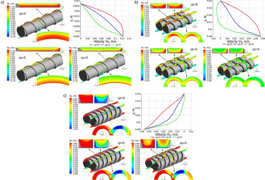
Polymers 2022, 14, 274                                                                                            2 of 28

                         outputs and to show the trends on the material reaction to hundreds of potential input
                         data configurations. It allows to get quickly the process map for identifying the requested
                         process parameters, according to the targeted materials and the selected screw profile,
                         that is, distribution of the thermo-mechanical results (temperature, pressure, viscosity,
                         filling) along the screw, detailed energy balance of the process, residence time analysis, etc.
                         The scale-up modules of the software allow the transferring of processes to machines with
                         larger or smaller diameters. Starting from the model process, the geometry of the target
                         design and the associated process parameters are calculated on the basis of transfer rules.
                               However, there are also some shortcomings in practical use. The important one is that
                         the global models which describe the complete extrusion process including solid transport,
                         polymer melting and melt flow are based on the relatively simple 1D or 2D models, and do
                         not allow looking into details of the process.
                               Many important books have been written on polymer extrusion, e.g., by Fischer [1],
                         Schenkel [2], Mc Kelvey [3], Fenner [4], Tadmor and Klein [5], Potente [6], Hensen et al. [7],
                         White [8], White and Potente [9], Tadmor and Gogos [10], White and Kim [11], Vlachopou-
                         los [12], Rauwendaal [13], Lafleur and Vergnes [14], Vlachopoulos and Polychronopou-
                         los [15], Chung [16], Noriega and Rauwendaal [17], Kohlgrüber [18,19], Campbell and
                         Spalding [20], and many others [21–33]. However, only a few of them have been de-
                         voted wholly to twin screw extrusion, namely the books of White on both co-rotating and
                         counter-rotating extrusion [8,9,11] and Kohlgrüber on co-rotating extrusion [18,19].
                               This paper is written in honor of Prof. James L. White who was a pioneer in studying
                         and modeling twin screw extrusion, both co-rotating and counter-rotating. A comprehen-
                         sive approach to process modeling is presented which includes the solid polymer transport,
                         the polymer plasticating, and the flow of molten polymer. These are based on strong
                         experimentation. The software used for global simulation of twin screw extrusion is also
                         reviewed, as well as CFD modeling of the process is presented with the modeling examples
                         which show the details of the process, which are not available when using the global
                         software. Optimization and scaling twin screw extrusion are also covered. And finally,
                         the future prospects of developments and research of twin screw extrusion are discussed.

                         2. Twin Screw Extrusion
                              Twin screw extrusion is divided due to the direction of the screw’s rotation into:
                         co-rotating extrusion, when the screws rotate in the same direction (Figure 1), and counter-
                         rotating extrusion, when the screws rotate in the opposite direction (Figure 2). Twin screw
                         extrusion can be performed with varying degrees of meshing. And so, it stands out:
                         extruders with non-intermeshing screws, tangential or separated, and extruders with
                         intermeshing screws, partially or closely intermeshing (with a special type of self-wiping
                         screws). Three practically used, twin screw extrusion techniques can be distinguished:
                         intermeshing co-rotating operations (including self-wiping), non-intermeshing tangential
                         counter-rotating operations, and intermeshing counter-rotating operations.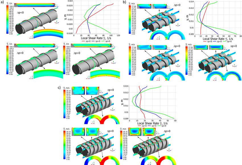
Polymers 2022,14,
Polymers2022, 14,274
x FOR PEER REVIEW 3 of
of2828
ers 2022, 14, x FOR PEER REVIEW 3 of 28
Figure1.1.The
Figure Thepolymer
polymerflow
flowininthe
theco-rotating
co-rotatingtwin
twinscrew
screwextruder:
extruder:QQ d—drag flow, Qp—pressure
d —drag flow, Qp —pressure
Figure 1. The polymer
flow, Qa —axial flow, Ql —leakage flow (adopted with permission from:p—pressure
flow, Q aflow in
—axial the co-rotating
flow, Q l—leakage twin screw
flow extruder:
(adopted with Q d—drag flow,
permission Q
from: Wilczyński,
Wilczyński,K.K.Rheology
Rheologyin
flow, Qa—axial Polymer
flow, QlProcessing.
—leakage flow (adopted
Modeling with permission
and Simulation; from: Verlag:
Carl Hanser Wilczyński, K. Rheology
Munich in
2021 [34]).
in Polymer Processing. Modeling and Simulation; Carl Hanser Verlag: Munich 2021 [34]).
Polymer Processing. Modeling and Simulation; Carl Hanser Verlag: Munich 2021 [34]).
Figure 2. The polymer flow in the counter-rotating twin screw extruder: (a) leakage flows, Qc—
Figure 2. The polymer flow in theQcounter-rotating
f—flight flow, Qttwin screw extruder: (a) leakage Qsflows, Qflow,
c—
Figure 2. Theflow,
calendering polymer —pressure
flow in the counter-rotating (tetrahedral)
twin screwflow,
extruder: —side
(a) leakage (b) C-shaped
flows, Qc —
calendering flow, Qf—flight
chamber, 1—side flow, Qt—pressure
surface (tetrahedral)
of the screw flow, Qsurface,
flight, 2—barrel s—side 3—front
flow, (b)surface
C-shaped of the screw flight,
calendering flow, Qf —flight flow, Qt —pressure (tetrahedral) flow, Qs —side flow, (b) C-shaped
chamber, 1—side surface ofofthe
4—surface thescrew
screwflight, 2—barrelwith
root (adopted surface, 3—front
permission surface
from: of the screw
Wilczyński, flight, in Polymer Pro-
K. Rheology
chamber,
4—surface of the 1—side
screw Modeling
root surface
(adopted of permission
with the screw flight,
from:2—barrel surface,
Wilczyński, 3—front
K. Rheology surface Pro-
in Polymer of the screw flight,
cessing. and Simulation; Carl Hanser Verlag: Munich 2021 [34]).
4—surface of the screw root (adopted with permission
cessing. Modeling and Simulation; Carl Hanser Verlag: Munich 2021 [34]). from: Wilczy ński, K. Rheology in Polymer
Processing.
Twin Modeling
screw and Simulation;
extruders areCarl Hanser
mostly Verlag:
used Munich 2021of
for processing [34]).
thermally sensitive poly-
Twin screw
mers, extruders
e.g., PVCare mostly used
(polyvinyl for processing
chloride), of thermally
and for specialty sensitive
operations, e.g., poly-
compounding, pol-
Twin screw extruders are mostly used for processing of thermally sensitive polymers,
mers, e.g., PVCymer
(polyvinyl chloride),
filling and and for specialty operations, e.g., compounding, pol-
reinforcing.
e.g., PVC (polyvinyl chloride), and for specialty operations, e.g., compounding, polymer
ymer filling and reinforcing.
The mechanism of polymer flow in twin screw extruders differs from that one in sin-
filling and reinforcing.
The mechanism
gle screw of polymer
extrudersflowandin totwin
a largescrew extruders
extent depends differs
on thefrom that one
meshing in sin-In single screw
degree.
The mechanism of polymer flow in twin screw extruders differs from that one in single
gle screw extruders
machines,and to a large
the polymer extent depends on the meshing degree. In single screw there is also a
screw extruders and to aflowlarge is of dragdepends
extent type, while in twin
on the meshingscrewdegree.
machines In single screw
machines, the positive
polymerdisplacement
flow is of drag type, while in twin screw machines there is also a
machines, the polymer mechanism flow is of drag which is dependent
type, while in twin on thescrewdegree of screws
machines theremeshing.
is also
positive displacement
It occurs mechanism
most fully inwhich
the is dependentcounter-rotating
intermeshing on the degree ofextruders.
screws meshing.
In the non-intermesh-
a positive displacement mechanism which is dependent on the degree of screws meshing.
It occurs mosting
fullyscrews,
in the intermeshing counter-rotating extruders. In thethe non-intermesh-
It occurs mostthisfullymechanism does notcounter-rotating
in the intermeshing occur. Generally,extruders. closer
In thethe meshing is, the
non-intermeshing
ing screws, this mechanism
transport does not
mechanism is occur.different.
more Generally, the closer the meshing
Non-intermeshing extruders is,resemble
the basically
screws, this mechanism does not occur. Generally, the closer the meshing is, the transport
transport mechanism
single screwis more different. Non-intermeshing extruders resemble basically
mechanism is extruders and therefore
more different. do not have
Non-intermeshing such good
extruders transportability
resemble basically as the closely
single screw
single screw extruders
intermeshing and therefore
screws. do not have such good transportability
extruders and therefore do not have such good transportability as the closely intermesh- as the closely
intermeshingingscrews.Another important difference is the polymer velocity distribution in the extruder. In
screws.
Another importantscrewdifference
twinAnother machines,
important is this
the polymer
distribution
difference isvelocity distribution
theispolymer
complex in the
and difficult
velocity extruder.
to describe
distribution In themathemati-
in extruder.
twin screw machines,
cally. this
However, distribution
this is
complicated complexnature andof difficult
the flow to describe
causes that mathemati-
twin
In twin screw machines, this distribution is complex and difficult to describe mathematically. screw extruders have
cally. However,goodthismixing
However, complicated
this and nature of
devolatilizing
complicated the abilities
nature flow
of thecauses
and that
flow are twin screw
twinextruders
characterized
causes that by good
screw have
heat exchange
extruders and
have good
good mixing mixing
and devolatilizing
fast polymer abilities and
plasticating.abilities
and devolatilizing are characterized
The difficulty by
and areofcharacterized good
describing such heat
by good exchange
a flow, and
heathowever,
exchange makes the
and fast
fast polymer polymer
plasticating.
twin screw The difficulty
extrusion theory of describing
less developed suchthana flow,
the however,
single screw
plasticating. The difficulty of describing such a flow, however, makes the twin makes
process thetheory.
twin screw extrusion
screwTwin theory
screw
extrusion less developed
machines
theory thansignificant
have
less developed thethan
single
thescrew
singleprocess
disadvantages theory.
alongside
screw process theory.their advantages.
Twin screw
They machines have significant
are expensive, structurallydisadvantages alongside
complex and difficult their advantages.
to manufacture.
They are expensive, structurally complex and difficult to manufacture.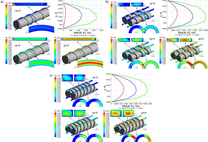
Polymers 2022, 14, 274                                                                                             4 of 28

                             Twin screw machines have significant disadvantages alongside their advantages.
                         They are expensive, structurally complex and difficult to manufacture.

                         2.1. Co-Rotating Twin Screw Extrusion
                               Co-rotating twin screw machines are mainly applied for compounding, e.g., polymer
                         mixing, devolatilization, filling, reinforcing or reactive extrusion. The schematic of the co-
                         rotating process is depicted in Figure 1.
                               In this process, the polymer flows from one screw to the other and moves in an open
                         figure-eight pattern, along with the so-called twisted eight. There is a counter-rotating
                         movement in the inter-screw gap, as a result of which high shear stresses are produced
                         in this area. And therefore, this method is used in compounding.
                               Co-rotating twin screw extrusion is usually performed with metered feeding (starve
                         feeding), which makes the pressure profile in the extruder not continuous, and it contains
                         sections where the pressure is reduced to zero. In these areas, i.e., in areas where pressure
                         is not produced, the feeders of various additives may be placed, e.g., for polymer filling,
                         polymer reinforcing or modifying. In these areas, it is also possible to place the devices for
                         devolatilization or removal of chemical reaction products during reactive extrusion.
                               In co-rotating machines, during each screw rotation, the polymer is transferred be-
                         tween the screws. The flow of polymer is dragged so that it resembles the flow in a single
                         screw machine in this respect. However, when moving between the screws, the polymer
                         travels a longer path and undergoes higher shearing.
                               The flow of polymer in co-rotating machines is the result of the movement of the screws
                         relative to the barrel, as well as the pressure gradient in the machine. It is the pressure-drag
                         flow which takes place in open channels between screws (alternately one and the other)
                         and the barrel.

                         2.2. Counter-Rotating Twin Screw Extrusion
                              Counter-rotating twin screw machines are used mainly for extruding profiles from
                         thermally sensitive materials, e.g., PVC (polyvinyl chloride). The schematic of the counter-
                         rotating process is depicted in Figure 2.
                              Counter-rotating extruders, in comparison with single screw extruders, provide better
                         feeding the extruder with polymer (especially in the case of polymers in the form of powder
                         or polymers exhibiting slip properties), and provide a shorter and less varied residence
                         time of the polymer particles in the extruder.
                              In the counter-rotating extruders, the polymer essentially does not flow from one screw
                         to the other, as in the co-rotating one. There is a co-rotating movement in the inter-screw
                         gap so that high shear stresses are not produced in this area, as in the co-rotating extrusion.
                              Counter-rotating extrusion, as with co-rotating extrusion, is usually performed with
                         metered feeding (starve feeding), which results in the pressure profile in the extruder being
                         non-continuous and having sections where the pressure is reduced to zero.
                              The flow of material in the counter-rotating machine differs totally from that one
                         in the single screw machine but also differs from the one in the co-rotating machine.
                         The essence of this flow is the so-called positive displacement mechanism that does not
                         occur in other extrusion variants. The positive displacement is dependent on the degree of
                         screws meshing. It occurs most fully in the closely intermeshing counter-rotating screws.
                         There is no drag flow here so the energy dissipation is insignificant.
                              The flow in the counter-rotating machine is mainly performed in a closed space,
                         in the C-shaped chamber, the so-called C-chamber, shown in Figure 2b. There are also
                         various types of leakage flows, schematically shown in Figure 2a.
                              The C-chamber is bounded by six surfaces, the screw root surface, the barrel sur-
                         face, the screw flight side surface (twice), and the front surface of the screw flight (twice).
                         There are leakage flows between these surfaces, i.e., the calendering flow Qc in the gap
                         between the screw root and the screw flight, the flight flow Qf in the gap between the screw
                         flight and the barrel, the back pressure inter-screw flow Qt (tetrahedron flow) in the tetra-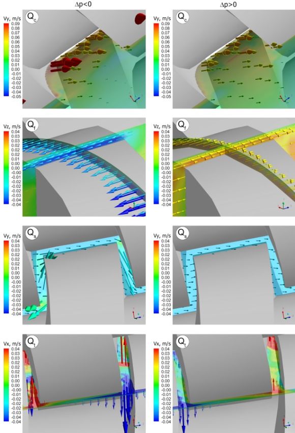
Polymers 2022, 14, 274                                                                                             5 of 28

                         hedral gap between the screw flight flanks (in the radial direction), and the side flow Qs
                         in the side gap between the flight flanks of screws (in the tangential direction).

                         3. Process Modeling
                              When modeling the twin screw extrusion process, the global approach for modeling
                         is needed. It is necessary to describe the transport of solid polymer, the plasticating of
                         polymer and the flow of molten polymer. The flows of molten polymers are rather well
                         known. However, the transport of solids and polymer plasticating are poorly understood.
                         The correct model of polymer plasticating is fundamental for global process modeling.

                         3.1. Solid Transport
                                A transport of the solid material in the single screw extruder was modeled first by Dar-
                         nell and Mol [35] who described the material movement in the screw and the pressure de-
                         velopment. They assumed the polymer particles to be compacted into the non-deformable
                         bed, and this solid bed flows as a result of the action of friction forces exerted by the barrel
                         and the screw on the polymer granules. This first, basic model was later extended, e.g.,
                         by Tadmor and Broyer [36,37]. The research on solid transport in single screw extruders
                         was reviewed in detail by Schöppner et al. [38,39]. It is worth noting that although many
                         researchers extended the model of Darnell and Mol [35], the principal analysis has not been
                         changed and has been fundamental for the modeling of extrusion for years.
                                The problem of modeling the transport of solid material in extruders may be solved
                         by using the DEM method (discrete element method). The first studies using this method
                         were performed by Pohl and Potente [40] who modeled the flow in the region of the hopper
                         inflow. The basic extrusion studies were performed by Moysey and Thompson [41,42]
                         who modeled the compacting granules and the pressure development in the screw [43,44].
                         Advanced modeling of the solid transport using the DEM method was carried out by
                         Schöppner et al. [38,39] who fully modeled the phenomena that occur in the solid transport
                         zone considering the pressure development and the screw filling.
                                Solid transport in the twin screw extrusion was investigated mostly for co-rotating
                         extruders, for example, by Carrot et al. [45], White and Bawiskar [46], Potente et al. [47],
                         and Wong et al. [48].
                                The first model of solid transport in the intermeshing co-rotating extruder was devel-
                         oped by Carrot et al. [45]. This model is similar to that commonly used in single-screw
                         extruders, however, it includes two transport mechanisms: the first one in the screw chan-
                         nel, and the second one is the axial transport in the intermeshing area. The model enables
                         to predict the filling of screws towards the geometry and the process operating parameters.
                                White and Bawiskar [46] observed that in co-rotating machines there were two areas
                         of solid transport: one in the upper nip between the screws which appeared at the low
                         screw speed and flow rate, and the second one of Archimedean type that was seen near
                         the nip on the underside of the screw and was more important at the high screw speed and
                         flow rate.
                                Potente and Melish [47] presented a different approach. They divided the conveying
                         zone into the partially filled feed zone and completely filled compression zone. Force and
                         torque balances were drawn up for three different volume elements and, with the solutions
                         obtained for these, it was possible to calculate the maximum conveyable throughput,
                         the pressure profile and the drive power that was required for the solids conveying zone.
                                Studies on solid transport in counter-rotating machines were limited. Doboczky
                         first [49] discussed this issue, while Wilczyński and White [50] experimentally investigated
                         it. They observed that near the hopper, the solid granules were distributed above the screws
                         and were freely conveyed along the screws. However, the granules were mainly conveyed
                         in the bottom region of the barrel, and only a small fraction of them was conveyed in the up-
                         per region of the screws. The granules were collected in the bottom region of the barrel
                         adjacent to the pushing flights of screws, and these subsequently were heated both by
                         the barrel and by being dragged into the gap between the screws.
Polymers 2022, 14, x FOR PEER REVIEW 6 of 28
Polymers 2022, 14, 274 6 of 28
adjacent to the pushing flights of screws, and these subsequently were heated both by the
barrel and by being dragged into the gap between the screws.
3.2. Plasticating
3.2. Plasticating
The first studies on plasticating in the single screw machine were carried out by Mad-
The first studies on plasticating in the single screw machine were carried out by Mad-
dock and Street [51,52]. They proposed the “screw pulling out technique” that involved
dock and Street [51,52]. They proposed the “screw pulling out technique” that involved
stopping the extruder, rapidly cooling the barrel and then pulling out the screw of the ex-
stopping the extruder, rapidly cooling the barrel and then pulling out the screw of the
truder. The cross-sections of the material removed from the screw were enabled to get to
extruder. The cross-sections of the material removed from the screw were enabled to get
know the plasticating mechanism. It was observed that a melt layer was formed between
to know the plasticating mechanism. It was observed that a melt layer was formed be-
the barrel and the solid which was scraped off by the transverse flow in the screw and was
tween the barrel and the solid which was scraped off by the transverse flow in the screw
accumulated near the active flight of the screw. The solid was gradually melted by the heat
and was accumulated near the active flight of the screw. The solid was gradually melted
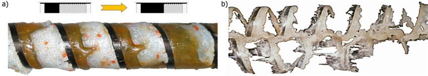
conducted from the barrel and by viscous dissipation in the melt (Figure 3a).
by the heat conducted from the barrel and by viscous dissipation in the melt (Figure 3a).
Figure 3.
Figure 3. Melting
Meltingmechanisms
mechanisms forfor
polymer extrusion:
polymer (a) CSM
extrusion: mechanism
(a) CSM (Contiguous
mechanism Solid Melt-
(Contiguous Solid
ing) for flood fed single screw extrusion [53] (b) melting mechanism for counter-rotating twin screw
Melting) for flood fed single screw extrusion [53] (b) melting mechanism for counter-rotating twin
extrusion [54].
screw extrusion [54].
Tadmor et
Tadmor et al.
al. [55–57]
[55–57] did did similar
similar experimentation
experimentation and and developed
developed the the first
first model
model of
of
polymer plasticating in the single screw extruder which
polymer plasticating in the single screw extruder which was fundamental for the theorywas fundamental for the theory
of extrusion
of extrusion and and enabled
enabled us us toto develop
develop the the first computer model
first computer model of of this
this process,
process, thatthat is,
is,
the EXTRUD
the EXTRUDprogram program[58]. [58].The
Themodelmodel of of plasticating
plasticating waswas obtained
obtained by considering
by considering the
the pro-
profiles
files of velocity
of velocity andand temperature
temperature in thein the polymer
polymer meltmelt
filmfilm
andandthe the profile
profile of tempera-
of temperature
ture in the solid bed. An energy balance was made at the
in the solid bed. An energy balance was made at the interface solid/melt and the interface solid/melt and the mass
mass
balance was performed in the solid and in the melt film.
balance was performed in the solid and in the melt film. These enabled us to predict These enabled us to predict the
plasticating
the plasticating rate.rate.
These studies
These werewere
studies laterlater
extended by a more
extended detailed
by a more description
detailed of solid
description of
conveying
solid conveying[36,37], and by
[36,37], andconsidering
by considering somesome delaydelay
in plasticating [59]. [59].
in plasticating
Many other studies were performed by using the “screw pulling out” technique, and
they confirmed the Tadmor Tadmor plasticating
plasticating model. model. This model was later extended by other
researchers and new new models
models were were developed
developed for for non-conventional
non-conventional screws. screws. These were
recently discussed by by Wilczy
Wilczyński
ński et et al.
al. [60].
[60].
„screw pulling
The “screw pulling out out technique”
technique” is is aa time-consuming
time-consuming method. method. Therefore, several
other concepts
concepts were wereproposed
proposedfor forstudying
studying thetheplasticating
plasticating of polymers
of polymers in extrusion. Liu
in extrusion.
et al.et[61]
Liu al. applied
[61] appliedglassglass
windowswindows in theinbarrel, Noriega
the barrel, et al. [62]
Noriega used
et al. [62]advanced
used advancedoptical
optical
methods methods for observing
for observing the plasticating
the plasticating profile, andprofile,
Wang andandWang
Minand[63] Min
applied [63]anapplied
ultra-
an ultrasound-based system for monitoring the plasticating
sound-based system for monitoring the plasticating in the twin screw extruder. Aigner et in the twin screw extruder.
Aigner
al. [64] et al. [64] proposed
proposed an ultrasonican ultrasonic
system for system for determining
determining the plasticating
the plasticating in the single
in the single screw
screw
extruder.extruder.
Yu etYu al.et[65]
al. [65] presented
presented a visualization
a visualization conceptwith
concept withaa transparent
transparent barrel
equipped with four cameras to observe the flow patterns of polymers in a novel type of
co-rotating non-twin
non-twin screwscrew geometry.
geometry.
Many researchers extended the models of Tadmor and Klein [5], however, the basic
analysis
analysis remained
remainedunchanged
unchangedand andwas wasusually
usually the basis
the basisforfor
modeling
modeling thethe
extrusion
extrusion process.
pro-
cess. It is important to note that the plasticating models presented so far, that is the models
basedIton the a priori
is important toassumed
note thatmechanism
the plasticating are not universal
models and are
presented notthat
so far, valid is for
the various
models
polymers,
based on the various
a priorioperating
assumedconditions,
mechanismand arevarious screw and
not universal geometry.
are notThese
valid models are
for various
useful only for predicting qualitatively the trends in plasticating
polymers, various operating conditions, and various screw geometry. These models are of polymers in extruders.
usefulPlasticating of polymers
only for predicting in extruders
qualitatively can bein
the trends simulated
plasticatingby solving
of polymersthe conservation
in extruders.
equations of fluid mechanics with a constitutive equation for the polymer being melted.
This concept was presented first by Viriyayuthakorn and Kassahun [66] who devel-
oped the 3D FEM (Finite Element Method) model without assuming any plasticating
mechanism. The modeling problem was solved with the use of functional dependence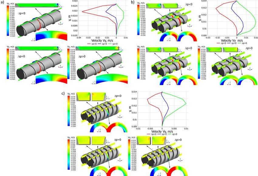
Polymers 2022, 14, 274                                                                                           7 of 28

                         of the specific heat on temperature. The solution of equations of motion and energy
                         determined the solid/melt regions which were defined by the temperature distribution.
                         Syrjäla [67] made 2D simulations of plasticating without any mechanism of it assumed.
                         However, in both cases, the simulations were not validated by experiment.
                                Altinkaynak et al. [68] carried out experimental and theoretical research on the model-
                         ing of plasticating using this approach. The two-phase flow of solid and melt was modeled
                         with the Cross-WLF rheological equation which enabled to determine the solid as a high-
                         viscous fluid, while the melt was determined as a low-viscous fluid. Hopmann et al. [69]
                         solved this problem with the use of FVM (Finite Volume Method) method, applying the rhe-
                         ological model of Carreau. Kazmer et al. [70] developed this approach for barrier screws
                         and Lewandowski and Wilczyński [71] for conventional screws.
                                Contrary to the plasticating in single screw extruders, the research on plasticating
                         in twin screw extruders was limited. This research involved mostly self-wiping co-rotating
                         extruders, e.g., by White and Bawiskar [46], Todd [72], Sakai [73], Wong [74], Carneiro
                         et al. [75,76], and Gogos et al. [77–80]. Potente and Melish [81], and White and Bawiskar [82]
                         developed the models fundamentally based on the classical Tadmor model [5] for single
                         screw extrusion, assuming the gradual development of a melt layer from the barrel towards
                         the screw. White and Bawiskar [82] modeled the formation of two stratified layers of molten
                         polymer in contact with the hot barrel and solid granules in contact with the colder screw.
                         Potente and Melisch [81] proposed a model based on plasticating the particals uniformly
                         suspended in the molten polymer. Similar model was proposed by Liu et al. [61]. Vergnes
                         et al. [83,84] and Zhu et al. [85] developed the models based on the analysis of the flow of
                         solid/liquid dispersion with some equivalent viscosity. These studies were reviewed and
                         discussed by Teixeira [86].
                                Plasticating in counter-rotating extruders is less known. Limited observations were
                         presented by Janssen [87], and White et al. [88,89] which indicated that plasticating takes
                         place faster than in intermeshing co-rotating extruders. Wilczyński and White [50] proposed
                         the mechanism of plasticating in intermeshing counter-rotating extruders. They observed
                         that plasticating is initiated both between the screws and at the barrel. The plasticating
                         between the screws is initiated by frictional work on the granules by the calendering
                         stresses between the screws. The plasticating action at the barrel is induced by a barrel
                         temperature higher than the melting point and propagated by viscous dissipation heating
                         of the melt film produced. Based on these observations, the models were developed for
                         plasticating in both those regions [54]. Further studies on plasticating were presented by
                         Wang and Min [63,90] and by Wilczyński et al. [91].

                         3.3. Flow of Molten Polymer
                               Rowell and Finlayson [92] were the first to analyze the Newtonian flow of viscous
                         oils in single screw machines (screw pumps) and developed the models of drag flow and
                         pressure flow. This analysis was extended to extrusion of polymers by Carley et al. [93]
                         who modeled one-dimensional flow through a rectangular channel of infinite width. Later,
                         the transverse flow caused by the screw flights was considered by Carley and Strub [94], and
                         Squires [95], the effect of channel curvature was investigated by Booy [96] and Squires [97]),
                         as well as the effect of flight clearance was modeled by Mallouk and McKelvey [98],
                         and Maddock [99].
                               Later studies included the non-Newtonian, one- and two-dimensional, isothermal flow
                         of the power-law fluid in a channel of infinite width, which were discussed and extended
                         by McKelvey [3] and Tadmor and Klein [5].
                               Since the basic models of Tadmor and Klein [5], many studies were performed to
                         improve the flow modeling in extruders, mostly by describing the two- or three-dimensional
                         flow in the actual screw geometry or by improving the thermal analysis, particularly
                         discussing the mechanical/thermal coupling, e.g., by Syrjäla [100,101], Ilinca and Hetu [102].
                         Miethlinger et al. [103–105] developed a novel heuristic approach for modeling the two-
                         or three-dimensional flow of the power-law fluid in single screw extruders. The issue of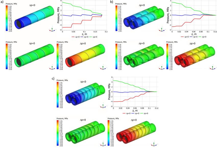
Polymers 2022, 14, 274                                                                                          8 of 28

                         modeling the melt flow in single screw extruders was recently reviewed and discussed by
                         Wilczyński et al. [60].
                               The studies on modeling the melt flow in twin screw extruders were limited. Erd-
                         menger [106,107] was the first to study the flow in co-rotating extrusion. He observed that
                         the polymer moved forward in a roughly helical eight-figure motion. The mechanism of
                         flow in the co-rotating machine is of drag type much as that in the single screw machine.
                         The geometry of the co-rotating screw configuration was discussed in detail by Booy [108].
                         The Newtonian flow in the fully filled elements was modeled by Booy [109], Denson and
                         Hwang [110], Szydłowski and White [111,112], and Tayeb et al. [113,114]. Later, the non-
                         Newtonian flow was modeled, e.g., by White et al. [115–118] and Potente et al. [119]. A fully
                         3D non-Newtonian FEM modeling was made by Ilinca and Hetu [102], Malik et al. [120],
                         and Vergnes et al. [121]. Avalosse and Rubin used the software Polyflow to model co-
                         rotating extrusion [122,123], and recently, Steinbichler et al. [124,125] presented a novel
                         approach to modeling the co-rotating extrusion based on the process parametric study.
                               Intermeshing counter-rotating extruders fundamentally differ from the single screw ma-
                         chines, and from the co-rotating machines. Kiesskalt [126], Montelius [127] and Schenkel [2]
                         were the first to consider these machines as positive displacement pumps. Doboczky [49,128]
                         and Janssen [87,129] developed the pumping characteristics for these machines, and they
                         first discussed the leakage flows. White and Adewale [130] modeled the flow considering
                         the level of intermeshing in the machine. Numerical FEM simulations presented Li and
                         Manas-Zloczower [131], and Kajiwara et al. [132]. Hong and White [133,134] used a FAN
                         (Flow Analysis Network) analysis to model the non-Newtonian flow. They developed screw
                         pumping characteristics for various screw elements which allowed the modelling of the flow
                         in various screw designs and calculate the pressure, fill factor, and temperature profiles.
                         Shah and Gupta [135,136] compared the flow in co-rotating and counter-rotating machines.
                         Recently, Wilczyński and Lewandowski [137] presented the fully 3D non-Newtonian FEM
                         computations to develop the pumping characteristics. These computations included the flow
                         in the C-chamber and the leakage flows.
                               Nowadays, 3D FEM simulations are available for single screw and twin-screw ex-
                         trusion which allow the description of the velocity and temperature distributions and
                         the pressure/flow rate relations, however, they require large computing resources and
                         major calculation time. Therefore, these computations cannot be applied for global process
                         modeling which requires hundreds of computing iterations. To avoid the time-consuming
                         computations, the concept of screw pumping characteristics was developed which are
                         defined by the dimensionless flow rate and the dimensionless pressure gradient [9]. These
                         characteristics can be described by the regression models and implemented into the itera-
                         tive procedures with reasonable computation accuracy and computation time. They were
                         developed both for single screw and twin-screw extruders, e.g., by White and Potente [9],
                         Rauwendaal [13], and recently by Wilczyński et al. [138–140].

                         4. CFD Modeling of Twin Screw Extrusion
                               In general, the global models which describe the complete extrusion process including
                         solid transport, polymer melting and melt flow are the lumped parameter models, and
                         are based on the relatively simple 1D or 2D models, and do not allow looking into de-
                         tails of the process. CFD modeling allows studying the process in detail calculating e.g.,
                         distributions of shear stress, shear rate, viscosity, residence time, etc.
                               Three-dimensional FEM computations with the use of CFD (Computational Fluid
                         Dynamic) software are available for both, single screw and twin screw extruders. These
                         allow the description of the velocity and temperature distributions and the pressure/flow
                         rate relations, and many others. The CFD software is a powerful tool for modeling of
                         polymer extrusion, however, its use is not easy. It requires a good knowledge of the process
                         under study, a good understanding of the modeling procedures, and correct formulating of
                         the boundary conditions, as well as proper interpretations of the modeling results. These
                         issues were discussed in the recently published book of Wilczyński [34].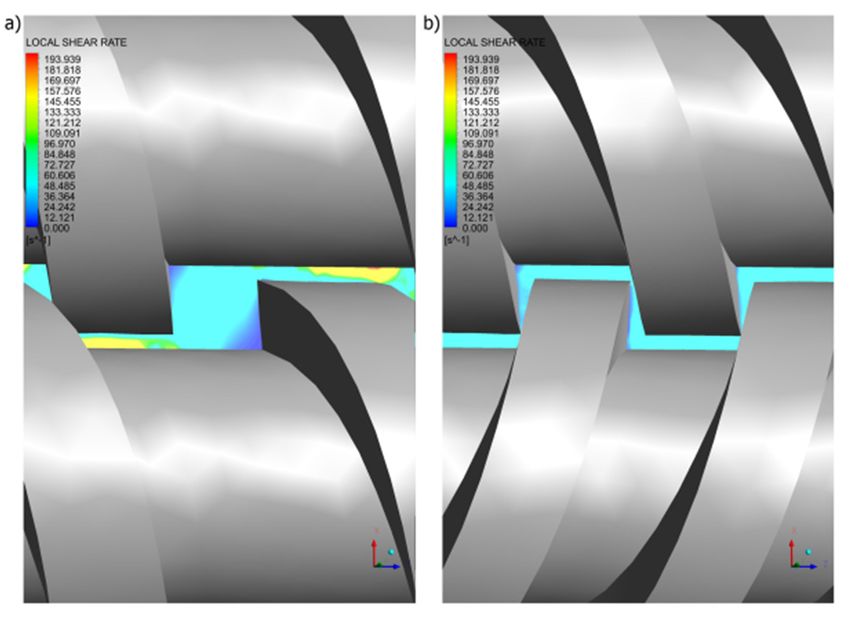
Polymers 2022, 14, 274                                                                                            9 of 28

                               ANSYS Polyflow software [141] can be used for modeling twin screw extrusion. It is
                         the FEM computational fluid dynamics (CFD) program for simulating the viscous and
                         viscoelastic flows which can be isothermal or non-isothermal, two- or three-dimensional,
                         steady-state or time-dependent. It is primarily used for solving the flow problems in poly-
                         mer processing; however, it can be also used for solving the rheology problems of other
                         materials such as glass or foodstuffs.
                               The flow of polymer in co-rotating extruders is the result of the relative movement of
                         the screws and the barrel and the pressure gradient in the machine. It is the pressure-drag
                         flow which takes place in open channels between screws (alternately one and the other)
                         and the barrel (Figure 1). In co-rotating extruders, during each screw rotation, the polymer
                         is transferred from one screw to the other, and moves in an open figure-eight pattern, along
                         the so-called twisted eight. The flow of polymer is dragged, so that it resembles the flow
                         in a single screw extruder in this respect. However, when moving between the screws,
                         the polymer travels a longer path and undergoes higher shearing. There is a counter-
                         rotating movement in the inter-screw gap, as a result of which high shear stresses are
                         produced in this area.
                               The flow of polymer in a counter-rotating extruder totally differs from that one in a sin-
                         gle screw extruder, but also differs from that one in a co-rotating extruder. The essence
                         of this flow is the so-called positive displacement mechanism that does not occur in other
                         extrusion processes. The degree of positive displacement is dependent on the degree of
                         screw meshing. It occurs most fully in the closely intermeshing counter-rotating extruders.
                         There is no drag flow so that the energy dissipation is insignificant. The flow in a counter-
                         rotating machine is mainly performed in a closed space, in the C-shaped chamber, shown
                         in Figure 2b. Since the channels are closed here, the material does not flow from one screw
                         to the other except for the leakage flows, schematically shown in Figure 2a, which reduce
                         the degree of positive conveying. There is a co-rotating movement in the inter-screw gap so
                         that high shear stresses are not produced in this area, as in the case of co-rotating extrusion.
                               In twin screw extrusion, both co-rotating and counter-rotating, the flow is three-
                         dimensional and unsteady since the screws rotate. To simplify the set-up of modeling of
                         such a flow problem, the mesh superposition technique (MST) has been developed for
                         the Polyflow software [141]. A finite element mesh is built for each part of the flow: one for
                         the flow domain (Subdomain 1) that is the inner part of the barrel without the screws, and
                         one for each screw (Subdomain 2, Subdomain 3). The set-up of the flow problem consists
                         in defining the boundary conditions. The screws rotate at a given screw speed N in the same
                         directions (co-rotating) or in the opposite direction (counter-rotating), and the velocity
                         vanishes at the barrel. The flow rate is imposed at the entry to the computational domain,
                         and it is also the outflow condition at the exit of the domain. In this paper, the flow problem
                         has been defined as an isothermal, 3D generalized Newtonian flow of the power law fluid.
                               The computation scheme is depicted in Figure 4. Three subdomains are distinguished,
                         for the flowing material (Subdomain 1) and for the screws (Subdomain 2, Subdomain 3).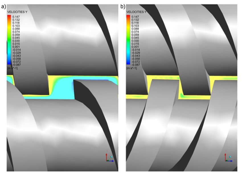
Polymers 2022, 14, 274 10 of 28
ymers 2022, 14, x FOR PEER REVIEW 10 of 28
Figure 4. The flow geometry and boundary conditions for twin screw extrusion: (a) boundary con-
Figure 4. The flow geometry and boundary conditions for twin screw extrusion: (a) boundary
ditions: BC1—inflow, BC2—outflow, BC3/BC4—Cartesian velocity, BC5—zero wall velocity, (b) co-
conditions:
rotating extrusion, BC1—inflow, BC2—outflow,
(c) counter-rotating BC3/BC4—Cartesian
extrusion (adopted velocity,
with permission from: BC5—zero wall
Wilczyński, K. velocity, (b)
Rheology in Polymer Processing. Modeling and Simulation; Carl Hanser Verlag: Munich 2021 [34]). Wilczyński, K.
co-rotating extrusion, (c) counter-rotating extrusion (adopted with permission from:
Rheology in Polymer Processing. Modeling and Simulation; Carl Hanser Verlag: Munich 2021 [34]).
The following flow boundary conditions were applied to define the process:
− at the inletTheto thefollowing flow boundary
flow domain: boundary conditions
BC1—inflow, were applied
the flowtorate define
(Qinthe process:
) = (Q) is
imposed,− at the inlet to the flow domain: boundary BC1—inflow, the flow rate (Qin ) = (Q) is
− at the outlet imposed,
of the flow domain: boundary BC2—outflow, vanishing normal forces
−
and tangentialat the outlet of are
velocities the imposed
flow domain: (fn and boundary
vs) = (0,BC2—outflow,
0), which means vanishing
that the normal
flow forces and
tangential
rate (Qout) = (Q) is imposed, velocities are imposed (f n and v s ) = (0, 0), which means that the flow rate
− on the screw (Qdomain:
out ) = (Q)boundary
is imposed, BC3—Cartesian velocity, Cartesian velocities are im-
posed − on the
(vx and screw
vy and vz)domain:
= (–N)—for boundary
co-rotatingBC3—Cartesian
extrusion, which velocity, Cartesian
means that thevelocities are
screw is rotated at the screw speed (N) counterclockwise, or (vx and vy and vz) = (N)—means that
imposed (v x and v y and v z ) = (–N)—for co-rotating extrusion, which
the screwextrusion,
for counter-rotating is rotated at the screw
which meansspeed that the (N)screw
counterclockwise, or (vx and vy and vz ) =
is rotated clockwise,
− (N)—for counter-rotating extrusion, which
on the screw domain: boundary BC4—Cartesian velocity, Cartesian velocities means that the screw is are
rotated
im- clockwise,
− on the screw domain: boundary BC4—Cartesian
posed (vx and vy and vz) = (–N) for both co-rotating and counter-rotating extrusion, velocity, Cartesian velocities are
imposed
which means that the screw (v x and v and v
isy rotated ) = (–N) for both co-rotating
z at the screw speed (N) counterclockwise, and counter-rotating extrusion,
− on the barrel which
wall:means
boundary thatBC5—zero
the screw is wallrotated
velocity, at the screw speed
vanishing normal (N)andcounterclockwise,
tangential
− on the barrel wall: boundary BC5—zero wall
velocities are imposed (vn and vs) = (0, 0), which means that the velocity vanishes velocity, vanishing normal and at tangential
velocities are imposed (vn and vs ) = (0, 0), which means that the velocity vanishes at
the barrel wall.
the barrel wall.
The boundary conditions, BC1—inflow (Qin) = (Q), and BC2—outflow, i.e., normal
forces and tangentialThe boundary
velocitiesconditions,
(fn and vs) =BC1—inflow
(0, 0), imply (Q that in )pressure
= (Q), and may BC2—outflow,
be developedi.e., normal
forces and tangential velocities (f and v ) = (0,
over the screws. Since the pressure at the screw element end is not known, the pressure
n s 0), imply that pressure may be developed
over the screws. Since the pressure at the screw
gradient is computed relative to the zero pressure at the element exit. Negative pressures element end is not known, the pressure
which may result from simulations do not mean negative pressures in the extrusion pro- pressures
gradient is computed relative to the zero pressure at the element exit. Negative
cess. which may result from simulations do not mean negative pressures in the extrusion process.
The simulations
The simulations were performed were performed
to study the to study the flow parameters
flow parameters distributionsdistributions
for dif- for differ-
ferent pressure gradients: positive gradient (∂p/∂z > 0, i. e., Δp < 0), zero gradient (∂p/∂z = (∂p/∂z =
ent pressure gradients: positive gradient (∂p/∂z > 0, i. e., ∆p < 0), zero gradient
0, i. e., Δp =0,0),
i. e.,
and∆pnegative
= 0), andgradient
negative(∂p/∂zgradient < 0, (∂p/∂z
i. e., Δp0,0), i. e., ∆p >Δp
where 0), is
where ∆p is the pressure
the pressure
difference between the pressure at the channel inlet and the pressure at the channelthe
difference between the pressure at the channel inlet and the pressure at channel outlet.
outlet.
In the case of co-rotating extrusion, the simulations started with the initial boundary
In the case of co-rotating extrusion, the simulations started with the initial boundary
condition BC1initial —outflow (Qout ) = (Q), with other conditions unchanged, which implies
condition BC1initial—outflow (Qout) = (Q), with other conditions unchanged, which impliesPolymers 2022, 14, x FOR PEER REVIEW 11 of 28
Polymers 2022, 14, 274 11 of 28
that pressure is not generated along the screw, and the flow rate is computed which is
that pressure
equal to the dragis notflow
generated
Qd, that along the screw,
is, there is no and the flow
pressure rate
flow, is computed
and which=is0,equal
we have (∂p/∂z i. e.,
to the
Δp = 0).drag
Then, flowtheQsimulations
d , that is, there
were is performed
no pressurewith flow,theand we boundary
basic have (∂p/∂z ∆p =
= 0, i. e.,BC1—
condition
0). Then,
inflow (Qthe
in) =simulations were performed
(Q), for different values Q =with 0, Qthe=Q basic
d, Q boundary
= 2Qd, whichcondition BC1—inflow
corresponds to the
(Q )
different
in = (Q), for different values Q =
pressure gradients: positive gradient,0, Q = Q , Q = 2Q ,
d zero gradient,
d which corresponds to the different
and negative gradient.
pressure
In the gradients:
case of positive gradient, extrusion,
counter-rotating zero gradient, the and negative started
simulations gradient.with the initial
In the case of counter-rotating extrusion, the
boundary condition BC1initial—outflow (Qout) = (Q), with other conditions simulations started withunchanged,
the initial
boundary
which condition
implies BC1initialis—outflow
that pressure not generated(Qoutalong
) = (Q),thewith other
screw, and conditions unchanged,
the flow rate is com-
which implies that pressure is not generated along the screw, and
puted which is equal to the net flow Qnet, that is, there is no pressure flow, and we have the flow rate is computed
which is
(∂p/∂z equal
= 0, i. e., to
Δpthe netThe
= 0). flownet Qnet , that
flow is, there is no
is composed pressure
of the flow,
chamber andand
flow we the
havedrag
(∂p/∂zcom- =
0, i. e., ∆p = 0). The net flow is composed of the chamber flow
ponents of leakage flows. Then, the simulations were performed with the basic boundary and the drag components of
leakage flows.
condition Then, the(Q
BC1—inflow simulations were performed with the basic boundary condition
in) = (Q), for different values Q = 0, Q = Qnet, Q = 2Qnet which
BC1—inflow (Qin ) = (Q), for different values Q = 0, Q = Qnet , Q = 2Qnet which corresponds
corresponds to the different pressure gradients: positive gradient, zero gradient, and neg-
to the different pressure gradients: positive gradient, zero gradient, and negative gradient.
ative gradient.
Pressure distributions are depicted in Figure 5, which in general are similar each
Pressure distributions are depicted in Figure 5, which in general are similar each
other, although they differ in detail. In the case of single screw extrusion (Figure 5a) and
other, although they differ in detail. In the case of single screw extrusion (Figure 5a) and
co-rotating extrusion (Figure 5b), for the positive pressure gradient, the pressure flow is
co-rotating extrusion (Figure 5b), for the positive pressure gradient, the pressure flow is
subtracted from the drag flow, while for the negative gradient, the pressure flow is added to
subtracted from the drag flow, while for the negative gradient, the pressure flow is added
the drag flow. In the case of the zero-pressure gradient, the pressure flow does not appear.
to the drag flow. In the case of the zero-pressure gradient, the pressure flow does not
In the case of counter-rotating extrusion (Figure 5c), for the positive pressure gradient,
appear. In the case of counter-rotating extrusion (Figure 5c), for the positive pressure gra-
the pressure leakage flows decrease the flow rate, while for the negative gradient these
dient, the pressure leakage flows decrease the flow rate, while for the negative gradient
increase the flow rate. In the case of the zero-pressure gradient, the pressure leakage flows
these increase the flow rate. In the case of the zero-pressure gradient, the pressure leakage
do not appear. However, the drag components of the leakage flows still exist.
flows do not appear. However, the drag components of the leakage flows still exist.
Figure 5. Pressure
Figure 5. Pressure distributions
distributionsfor
forextrusion
extrusionatatvarious
various pressure
pressure gradients
gradients (∂p/∂z),
(∂p/∂z), positive
positive (∆p(Δp <
< 0),
0), zero (Δp = 0) and negative (Δp > 0): (a) single screw extrusion, (b) co-rotating twin screw extru-
zero (∆p = 0) and negative (∆p > 0): (a) single screw extrusion, (b) co-rotating twin screw extrusion,
sion, (c) counter-rotating twin screw extrusion (adopted with permission from: Wilczyński, K. Rhe-
(c) counter-rotating twin screw extrusion (adopted with permission from: Wilczyński, K. Rheology
ology in Polymer Processing. Modeling and Simulation; Carl Hanser Verlag: Munich 2021 [34]).
in Polymer Processing. Modeling and Simulation; Carl Hanser Verlag: Munich 2021 [34]).Polymers 2022, 14, x FOR PEER REVIEW 12 of 28
Polymers 2022, 14, 274 12 of 28
It is worth noting the characteristic pressure pulsation for all the screw configurations
It isco-,
(single, worth
andnoting the characteristic
counter-), the so-called pressure
pressure pulsation
saw, which forisall the
the screw
result ofconfigurations
varying screw
(single, co-, and counter-), the so-called pressure saw, which is the
geometry in a given area of an analysis. At a certain point in the flow space, result of varying
the screw
screw
geometry in a given area of an analysis. At a certain point in the flow space,
flight and the screw channel alternate, which generates pressure pulsation. This phenom- the screw flight
and
enon is an inherent and always occurring feature of screw flows. It is also the cause is
the screw channel alternate, which generates pressure pulsation. This phenomenon of
an inherent and always occurring feature of screw flows. It is also the cause of pulsation
pulsation in the extruder output. The frequency of this pulsation is equal to the frequency
in the extruder output. The frequency of this pulsation is equal to the frequency of screw
of screw rotation. Counter-rotating twin screw extrusion seems to be the most stable pro-
rotation. Counter-rotating twin screw extrusion seems to be the most stable process,
cess, the pulsations are much lower than for single screw extrusion or co-rotating extru-
the pulsations are much lower than for single screw extrusion or co-rotating extrusion.
sion.
Distributions of the velocity components for different pressure gradients are shown
Distributions of the velocity components for different pressure gradients are shown
in Figures 6–8. In general, in the case of single screw extrusion and co-rotating extrusion,
in Figures 6–8. In general, in the case of single screw extrusion and co-rotating extrusion,
these are similar, and totally different than in the counter-rotating extrusion.
these are similar, and totally different than in the counter-rotating extrusion.
For single screw extrusion, the velocity component vx (Figure 6a), which is perpendic-
For single screw extrusion, the velocity component vx (Figure 6a), which is perpen-
ular to the screw axis, is decreased by the pressure flow at the positive pressure gradient
dicular to the screw axis, is decreased by the pressure flow at the positive pressure gradi-
and is increased by the pressure flow at the negative gradient. The velocity component vy
ent and is increased by the pressure flow at the negative gradient. The velocity component
(Figure 7a), also perpendicular to the screw axis, varies depending on the pressure gradient.
vy (Figure
The velocity 7a),component
also perpendicular
vz (Figure to 8a),
the screw
whichaxis, varies depending
is parallel to screw axis,on the
haspressure gra-
a parabolic
dient. The velocity component v z (Figure 8a), which is parallel to screw axis, has a para-
distribution, and increases with an increase of the pressure difference ∆p.
bolic distribution, and increases with an increase of the pressure difference Δp.
Figure 6. Distributions of the velocity vx for extrusion at various pressure gradients (∂p/∂z), positive
Figure 6. Distributions
(Δp < 0), zero (Δp = 0) of thenegative
and velocity(Δp
vx for extrusion
> 0): at various
(a) single pressure gradients
screw extrusion, (∂p/∂z),
(b) co-rotating twinpositive
screw
(∆p < 0), zero
extrusion, (∆p = 0) and negative
(c) counter-rotating (∆p > extrusion
twin screw 0): (a) single screw with
(adopted extrusion, (b) co-rotating
permission twin screw
from: Wilczyński, K.
extrusion,
Rheology in(c) counter-rotating
Polymer Processing.twin screwand
Modeling extrusion (adopted
Simulation; with permission
Carl Hanser from: 2021
Verlag: Munich Wilczy ński, K.
[139]).
Rheology in Polymer Processing. Modeling and Simulation; Carl Hanser Verlag: Munich 2021 [139]).Polymers 2022, 14, 274 13 of 28
Polymers 2022, 14, x FOR PEER REVIEW 13 of 28
Figure 7. Distributions of the velocity vy for extrusion at various pressure gradients (∂p/∂z), positive
Figure
(Δp Distributions
< 0),7.zero of the
(Δp = 0) and velocity(Δp
negative vy >for
0):extrusion
(a) singleatscrew
various pressure(b)
extrusion, gradients (∂p/∂z),
co-rotating twinpositive
screw
(∆p < 0), zero (∆p = 0) and negative (∆p > 0): (a) single screw extrusion, (b) co-rotating
extrusion, (c) counter-rotating twin screw extrusion (adopted with permission from: Wilczyński, twin screw
K.
extrusion,
Rheology in (c) counter-rotating
Polymer twin screw
Processing. Modeling andextrusion (adopted
Simulation; with permission
Carl Hanser from:2021
Verlag: Munich Wilczy ński, K.
[34]).
Rheology in Polymer Processing. Modeling and Simulation; Carl Hanser Verlag: Munich 2021 [34]).You can also read