MODEL 249/269/279/299 ELECTRON BEAM SOURCE - Telemark
←
→
Page content transcription
If your browser does not render page correctly, please read the page content below
MODEL 249/269/279/299
                        ELECTRON BEAM SOURCE
                                            INSTRUCTION MANUAL

       Copyright © TELEMARK, 1990-2019 – All rights reserved

                              April 2019

                            telemark.com

             Brand and product names are trademarks or
         registered trademarks of their respective companies.

              Current version of this manual can be found at
https://telemark.com/uhv-e-beam-sources/near-uhv-multi-pocket-sources/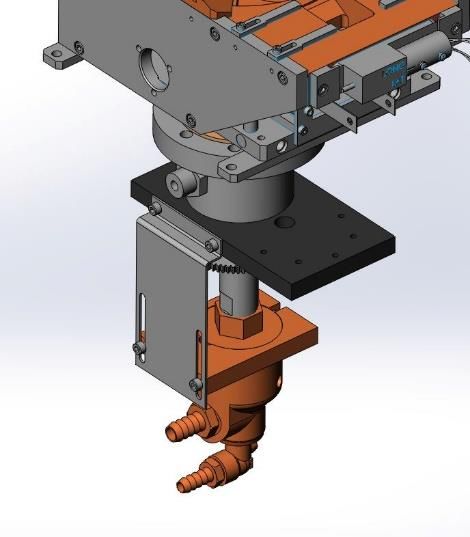
Telemark Model 249/269/279/299 Electron Beam Source Instruction Manual

                                                       SAFETY WARNING
HIGH (POTENTIALLY LETHAL) VOLTAGES ARE PRESENT WITHIN EVAPORATION
SYSTEM. GREAT CARE MUST BE EXERCISED WHEN PERFORMING
MAINTENANCE.

HUMAN CONTACT WITH THE VOLTAGES CAN BE FATAL.

SHORT ALL HV FEEDTHRU CONNECTIONS WITH A GROUNDING HOOK.

                             DANGER – HIGH VOLTAGE

2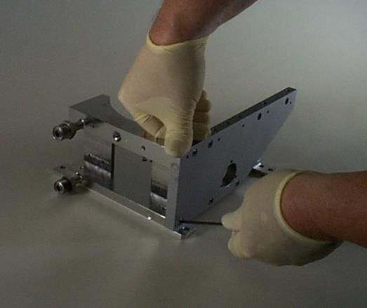
Telemark Model 249/269/279/299 Electron Beam Source Instruction Manual

                                                                    WARRANTY
This Electron Beam Source is guaranteed against faulty materials, function, and
workmanship for a period of 12 months after delivery from Telemark.

This warranty is valid only for normal use where regular maintenance is performed as
instructed. This warranty shall not apply if repair has been performed or an alteration
make by anyone other than an authorized Telemark representative or if a malfunction
occurs through abuse, misuse, negligence, or accident. No charge will be made for
repairs make under warranty at Telemark’s facilities. Defective parts will be repaired or
replaced at Telemark’s option. Customer will be responsible for freight charges to
Telemark’s facility.

For the safety of the Telemark technician’s customers are requested to supply a list of
materials which have been evaporated in the crucible when the electron beam source is
returned for repair.

                                           USER RESPONSIBILITY
The user is responsible for proper operation and ordinary maintenance of the
equipment, following procedures described in this manual, including reference
documents. Proper operation includes timely replacement of parts that are missing,
broken, or plainly worn. If the user has a reasonable doubt about understanding the use
or installation of a component, Telemark or your local representative should be called.

It is vitally important that the user properly install the equipment as described in Chapter
3 (Installation) of this manual, with particular attention to the correct grounding methods
described.

The Warranty will be void if the equipment is improperly installed and/or properly
grounded.

                                                                                     3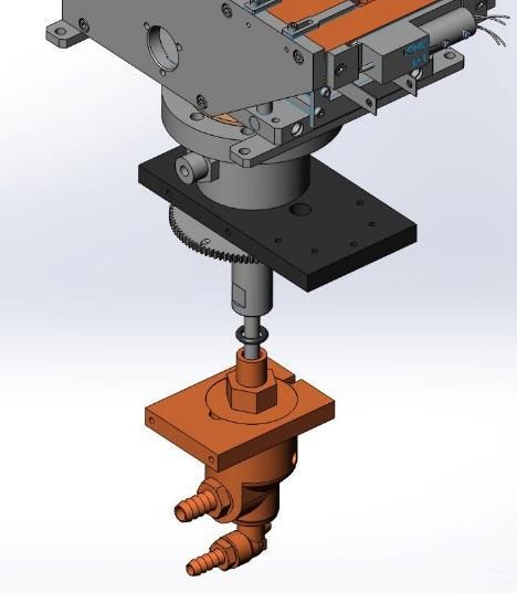
Telemark Model 249/269/279/299 Electron Beam Source Instruction Manual

                                                TABLE OF CONTENTS
    1   UNPACKING                                                         6

    2   DESCRIPTION                                                       7

    3   SPECIFICATIONS                                                    9

    4   INSTALLATION                                                     10
          Required Components                                            10
          Setting Up                                                     11
          Grounding                                                      12
          High Voltage                                                   13
          Ground Connections                                             13
          Two Source Installation                                        14

    5   OPERATION                                                        16
          General Operation – Startup                                    16
          General Operation – Shutdown                                   17
          Adjusting the Electromagnetic Field                            17

    6   SERVICING                                                        18
          Crucible Removal                                               18
          Crucible Replacement                                           18
          Emitter Removal                                                19
          Emitter Disassembly and Cleaning                               19
          Filament Replacement                                           20
          Emitter Rebuilding/Reassembly                                  20
          Source Disassembly                                             22
          Coil Assembly                                                  23
          Main Body Reassembly                                           23
          External Reassembly                                            25
          Quick Check                                                    26

    7   KITS AND ACCESSORIES                                             27
          Accessories                                                    29

4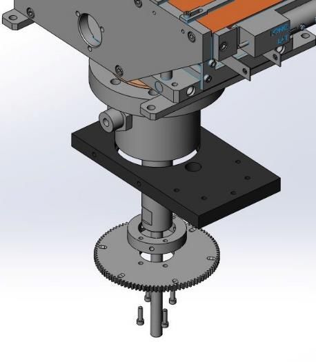
Telemark Model 249/269/279/299 Electron Beam Source Instruction Manual

      Replacement Crucibles                                        30
      Rebuild Kits                                                 31

8   TROUBLESHOOTING                                                33
      Power Problems                                               33
      Beam Problems                                                34
      Rotation Problems                                            35

                                                                                  5
Telemark Model 249/269/279/299 Electron Beam Source Instruction Manual

                                                                     UNPACKING
                                                                              1
Your electron beam source is packed into a specially designed double strength box and
surrounded with two and a half inches of rigid foam padding. Since packaging the
source for safe shipment is otherwise difficult, please save the box in the event that the
source ever needs to be returned for servicing. Telemark cannot be held liable for
sources which are damaged in transit as a result of improper packaging.

Inside the box are the source and installation kit. The installation kit includes: a set of
tools, a spare seal kit and an emitter rebuild kit. Please check the packaging list to make
sure no damage has occurred in transit. Inspect the emitter assembly for alignment of
the filament, anode plate and beam former. The source is ruggedly built and packaged
tightly to prevent damage. In the event of any deficiencies, please report them to your
vendor immediately. Also take care to read the warranty regarding the limits of
Telemark’s liabilities.

The finish on the metal parts of the source is the highest available. The source is
assembled under clean conditions and sealed in a polyethylene bag for shipment. A set
of white gloves is included for your use in unpacking and setting up the source to help
minimize contamination.

6
Telemark Model 249/269/279/299 Electron Beam Source Instruction Manual

                                                               DESCRIPTION
                                                                                 2
The electron beam source’s most notable features:

Some models have crucibles that can be removed from above by simply removing the
screws that hold them in place. This feature allows the crucible to be cleaned or
replaced without removing the source from the vacuum chamber or disassembling the
entire source. This process is described in the Servicing Manual.

The emitter assembly is a critical component in the operation of the electron beam
source. The parts that make up the emitter assembly are manufactured to exacting
standards. Telemark has developed several innovative changes to the emitter assembly
which make it more reliable and easier to assemble.

The sweep coils are sealed in a water-cooled solid copper block or are sealed in a
stainless steel can that is attached to a water-cooled solid copper block. This virtually
eliminates the possibility of damaging the coils thermally or mechanically during normal
production or handling. As long as proper water flow is maintained in the EB source and
care is taken not to drop it, the coils should last indefinitely.

Other features, such as heavy-duty screws with Helicoil® inserts in the copper in all
important fastening locations, reliable vacuum connections, and heavy-duty construction
in general, are designed to make the source serviceable for years of production.

                                                                                     7
Telemark Model 249/269/279/299 Electron Beam Source Instruction Manual
Figure 2-A Crucible Dimensions
“A” “B”
Size Inch mm Inch Mm
4cc .575 14.61 .885 22.48
7cc .500 12.70 1.125 28.58
15cc .670 17.02 1.485 37.72
25cc (Shallow) .680 17.27 1.855 47.12
25cc (Deep) .920 23.37 1.633 41.48
30cc (with Web) .790 20.07 1.920 48.77
30cc (W/O web) .940 23.88 1.800 45.72
40cc 1.020 25.91 2.030 51.56
8Telemark Model 249/269/279/299 Electron Beam Source Instruction Manual
SPECIFICATIONS
3
Specifications 249 269/279 299
EB Source EB Source EB Source
Electron Beam Deflection 270º 270º 270º
Power Rating 6 kW 10 kW 12 kW
High Voltage Range -6 kV to -10 kV -6 kV to -10 kV -6 kV to -10 kV
Lateral Coil Resistance 7.5 ohms 3.0 ohms 3.0 ohms
Longitudinal Coil 9.5 ohms 9.6 ohms 9.6 ohms
Resistance
Emission Current 0 to 500 mA @ 10kV Up to 1 amp @ 10kV Up to 1 amp @ 10kV
Filament Power 600 watts maximum 600 watts maximum 600 watts maximum
(50 Amps at 12 VAC (50 Amps at 12 VAC (50 Amps at 12 VAC
max). max). max).
Sweep Lateral Coil +/-1.5 amps +/-1.5 amps +/-1.5 amps
Sweep Longitudinal Coil +/-1.5 amps +/-1.5 amps +/-1.5 amps
Water Requirements 2 gpm (min.) at 6 kW 3 gpm (min.) at 10 kW 3 gpm (min.) at 10 kW
(Crucible) (Crucible) (Crucible)
2 gpm (min.) at 6 kW 3 gpm (min.) at 10 kW 3 gpm (min.) at 10 kW
(Source body) (Source body) (Source body)
Input water Input water Input water
temperature should be temperature should be temperature should be
60-70 F (15-21C) at a 60-70 F (15-21C) at a 60-70 F (15-21C) at a
pressure of 60 psi (4.2 pressure of 60 psi (4.2 pressure of 60 psi (4.2
kg/cm2), using a 3/8” kg/cm2), using a 3/8” kg/cm2), using a 3/8”
(10mm) line. (10mm) line. (10mm) line.
Crucible Volume Many options Many options Many options
available available available
9Telemark Model 249/269/279/299 Electron Beam Source Instruction Manual
INSTALLATION
4
Required Components
See figure 3-B
The following is the minimum list of components required for setting up the source for
safe operation.
1 High-voltage Feedthroughs – Two high-voltage feedthroughs rated at 15 kV @
70 amps. Bare copper straps are provided for use inside the chamber. Outside
the chamber use #6 AWG copper wire with lugs for attaching feedthrough to
transformer.
2 Tank Ground – Use a solid copper strap or copper wire (#6 AWG or greater and
up to seven strands, not copper braid) between tank and an 8 foot long copper
clad steel grounding rod. Connections must be free of oxide and extremely tight.
3 Transformer Cover – Mount filament (source) transformer as close to high-
voltage feedthroughs as possible in the transformer box provided with the
Telemark power supply.
4 Sweep Coil Feedthrough – All sources, except models 221, 508 and 528, have
an electromagnetic X-Y sweep coil and need a minimum of a four (4) pin low-
voltage feedthrough. Kapton® coated wire is supplied on the standard coil
connector Telemark #271-0125-1. Bare OFHC wire is used in the UHV assembly
Telemark #271-0125-3. Coil connector assembles come with two feet of wire
standard, optional lengths are available. See figure 3-A for reference code of
marked wires when shipped from the factory.
10Telemark Model 249/269/279/299 Electron Beam Source Instruction Manual
Figure 3-A Coil Wire Reference Code
5 Water Feedthrough – For sources that do not come from the factory installed on
flanges a water feedthrough is required. Use 3/8” O.D. x 1/16” wall 304 Stainless
tubing and weld into fittings provided with source and butt-weld to tubing dual
water feedthrough. We do not recommend the use of bellows inside the
chamber. Attach feedthrough tubing to 3/8” copper tubing outside chamber, use
compression fittings or other means to make this connection.
6 Water Filter – Use standard removable water filter on inlet. Position away from
chamber so that it is completely accessible for servicing.
7 Blowout Valve – Use three-way valve attached to air or nitrogen supply for
blowout.
8 Flowmeter – Use a flowmeter with an interlock switch on water outflow.
9 Interlocks – Install interlocks for Vacuum, Tank, High Vacuum, and Water. Other
interlocks should be installed using the Aux interlock input.
Setting Up
Note that it is important to never use mild steel for electron beam source mounting. This
includes mounting plates, standoffs or source shutter hardware. Mild steel could affect
the magnetic properties of the electron beam source resulting in poor performance or a
deformed electron beam. The best material to use is non-magnetic 304 stainless steel.
Set the source level with the required offset from chamber centerline. The source is
easiest to operate and observe in operation if placed facing forward and in front of the
11Telemark Model 249/269/279/299 Electron Beam Source Instruction Manual chamber centerline. The source may be mounted directly on a vacuum chamber baseplate, on stainless steel standoffs, a flange depending on the model and installation requirements. Custom designed mounting plates are available from the factory. Good contact between the base of the electron beam source and the baseplate of the vacuum chamber is important to earth ground the source through the chamber baseplate. A shutter should be mounted above and slightly behind the pocket. The shutter should obscure at least a one-hundred-degree cone above the pocket. A stainless disc makes a good, enduring shutter, provided it can be mounted ruggedly and detached easily for cleaning. 8 or 10 AWG copper wire is provided for the high voltage leads. These should be shortened to the smallest distance between source emitter and the feedthroughs, with a slight curve to allow for thermal expansion and contraction. Interlocks should be installed, so that the breaking of any interlock turns off the source. See the note on high voltages below as to why this is important. Grounding Proper grounding is the single most important aspect of the installation of the E-beam. During arcing events, RF noise is generated that must be properly driven to ground to avoid interference/damage. For this reason, the E-beam ground must be separate from the electronics rack ground and ideally as short as possible. Improper grounding can lead to poor performance, interference with other equipment, damage to E-beam electronics or other equipment, or even shock potential. Do not depend on water pipes for the system ground connection. Because of multiple joints and sealing compounds, water pipes typically do not make an earth ground. Keep in mind this is a high frequency as well as a DC ground. Regardless of the method of grounding, the first point of connection for the ground cable/strap is always the E-beam chamber. There should be a specially designed ground bar welded to the chamber for this purpose. The strap, if used, should be "sandwiched" between two bars to ensure a broad area connection. Connecting to Building Steel The best method known for grounding the E-beam is to tie the ground bar to building steel as close as possible using the appropriate grounding strap (varies based on the distance - see details below). One must verify that the building steel has a good connection to ground for this to be a viable solution. Be sure to remove any paint, rust, etc from under the connection point to the building steel. 12
Telemark Model 249/269/279/299 Electron Beam Source Instruction Manual

Because the connection is for an RF ground, surface area is more important than cross-
sectional area. It is critical to have a wide surface area of connection between the
grounding strap and the building steel.

 Distance Between E-Beam Chamber              Minimum Recommended Strap/Cable
 and Grounding Point

 < 10 Feet « 3 meters)                        #6 Gauge or larger gauge copper cable

 10-20 Feet (3-6 meters)                      #4 Gauge or larger gauge copper cable

 20-60 Feet (6-18 meters)                     2 inch by .035 inch thick copper strap

 > 60 Feet (> 18 meters)                      Contact Telemark for recommendations

                                 Table 4-1: Ground Strap Size

When in doubt, always go with the larger ground connection. You can never have too
good of a connection!

Do not use braided wire. Be sure that the connection is made to clean metal.

The power supply is connected to ground using the HV cable’s shield connection. The
power supply may sustain major damage if power is applied before the ground is
connected.

High Voltage
Use decals or other warning labels on the high voltage shield, at the front of the E-beam
chamber and on the door to the room to provide warning that lethal voltages are
present. Do not put any part of the body under a chamber while a source is running.
Always use a grounding hook as a matter of habit before touching any potentially high
voltage area, even when power supply is off. Always keep one hand in a pocket. Always
maintain a respectful fear of high voltages: familiarity does not make high voltages safe.

Ground Connections
In addition to the critical building (earth) ground described above, there are 6 other
ground leads that will attached to the ground bar on the E-beam chamber:

1. Source Transformer Box - connected using 6 AWG gauge wire

2. E-beam power supply - connected using 6 AWG wire

3. Safety cover over high voltage feedthroughs - connected using 12 AWG gauge wire

4. Sweep controller - connected using 12 AWG gauge wire

                                                                                       13
Telemark Model 249/269/279/299 Electron Beam Source Instruction Manual
5. TT-Controller - connected using 12 AWG gauge wire
6. Sweep cable ground connection - connected using 12 AWG gauge wire
There is not a required order for the above; simply connect each ground lead securely
to an open ground lug location on the ground bar. Ensure connections are secure prior
to turning on the power to the E-beam. Operating without one or more grounds properly
connected may cause damage to equipment or even harm to the operator.
Sweep
Filament Power Supply
Transformer
Power Supply
Controller
Figure 4-B Suggested Ground Installation
Two Source Installation
See Fig 3-C
To have a two-source installation work properly, a magnetic shunt bar must be placed
between the two sources so that the magnetics of the sources do not interfere with the
movement of positions of the dual electron beams. The shunt is usually a sandwich
alternating between magnetic and non-magnetic metal with an air gap between each
piece. Magnetic metals used are Mew metal or a mild steel .020 to .030 inch (0.50 to
0.75mm). Non-magnetic metals are non-magnetic stainless steel or copper .020 to .030
inch thick (0.50 to .75mm). One way of mounting the shunt to the magnet arms is with
304 stainless steel straps; other fastening methods may need to be used.
Sources must oppose each other for the sweep coils to work properly.
14Telemark Model 249/269/279/299 Electron Beam Source Instruction Manual
Figure 3-C Multi-Source Installation
15Telemark Model 249/269/279/299 Electron Beam Source Instruction Manual
5
OPERATION
General Operation – Startup
Load the crucible up to first rim with vacuum grade material. Make sure the view of the
crucible is unobstructed from the view port when the chamber is closed. Welding glass
(T9H is a convenient density) should be used when the beam intensity becomes too
bright for direct viewing. (It is always a good idea to put a clean, removable piece of
glass on the inside the chamber to prevent the port from being coated.) When the
chamber is in operating range on the order of 1x10⁻⁵ torr or better, set the operation
voltage, set the beam position to neutral, set the emission to zero, and reset the sweeps
amplitude to zero.
When you are satisfied that conditions are optimal, turn on the power supply high
voltage. Keeping an eye on the evaporant, very slowly turn up filament current. At
around 100mA the beam should become apparent on the melt. If not, see the following
paragraph. The beam should always be in the center of the crucible. As the emission is
increased, the sweep pattern can be enlarged to cover the melt. After the ion gauge has
stabilized and the material has stopped out-gassing and spitting, the shutter can be
opened. After the required thickness level is reached, close the shutter, and reduce the
emission to zero.
If the beam is not visible at 100mA of emission current, then adjust the beam position all
the way in and then all the way out and from left to right. If the beam does not become
visible at this time, do not under any circumstances try to increase the emission.
Instead, turn off the source emission current and the high voltage. Check the
longitudinal focus coil leads, be sure that they are not reversed, and go through the
checklist under the section on troubleshooting.
16Telemark Model 249/269/279/299 Electron Beam Source Instruction Manual
General Operation – Shutdown
After terminating the final layer of the run sequence, turn down the filament current, turn
off the high voltage, and allow the filament to cool for a few minutes before opening the
chamber. The emitter assembly is surrounded by water-cooled components, so through
radiation the filament will cool quickly. (A yellow oxide forms around the filament cavity if
the vent is too fast.) Always use a grounding hook before working around high
voltages.
Before removing the crucible for cleaning, make sure the water lines are blown out.
Adjusting the Electromagnetic Field
Position – The beam can be pulled towards the front of the crucible by:
• Reducing the high voltage (which also reduces beam intensity).
• Increasing the longitudinal coil current.
• Removing the shunt bar.
• Bringing the pole pieces farther in.
The beam can also be moved laterally by applying current to the lateral sweep coils.
Shape – As in the discussion above, the shape of the beam can be concentrated by
bringing the pole pieces all the way in. In general, the beam shape is optimal for
dielectrics if the pole pieces are two thirds of the way in, the shunt gar is added, and the
accelerating voltage is around 6kV.
Intensity – The intensity of the beam is maximized by having the filament, beam former
and anode plate aligned properly: see the service manual for your model electron beam
source. If the intensity seems limited, the filament alignment should be checked – it may
be warped, too far up, or even in backwards. The beam intensity is increased by turning
up the filament current.
17Telemark Model 249/269/279/299 Electron Beam Source Instruction Manual
6
SERVICING
It is particularly important to be familiar with the removal and replacement of the crucible
and the emitter, as these are the components most commonly removed for servicing.
Crucible Removal
Turn off the water and use the blowout valve to purge as much water from the gun as
possible. Undo the four #10-32 Allen Head screws, holding down the cover plate and
remove the plate carefully, setting down on clean lint-free tissue to avoid contaminating.
Remove the rotary water union and loosen up clamp on the feedthru. Lift the crucible
assembly out. Remove the 16 bolts on the crucible assembly, freeing the crucible.
Crucible Replacement
Always replace the copper gasket. Tighten the crucible screws. Insert crucible assembly
into the gun and feedthru, tighten clamps. Lower cover plate gently onto arms and
tighten four holding screws. Turn on water, observing base of crucible for any leaks.
CAUTION: MAKE SURE THAT A GROUNDING HOOK
IS USED TO SHORT ALL HV CONNECTION BEFORE
ANY WORK IS PERFORMED ON THE EMITTER
ASSEMBLY.
18Telemark Model 249/269/279/299 Electron Beam Source Instruction Manual
Photo 2 Emitter Assembly
Emitter Removal
Remove the two nuts and bolts holding the filament buss bars to the high voltage leads.
The emitter is attached to the base with a single #6-32 x 1/4" Allen screw. The most
convenient way to detach the emitter assembly is with a long handled Allen wrench (12"
long is fine), since in normal practice the emitter is extremely hot at this time. Pull the
emitter assembly straight out the front.
Emitter Disassembly and Cleaning
You will need several things for the disassembly/cleaning process:
• Alcohol to help free the tight screws.
• Wire to string the metal parts of your emitter for cleaning.
• A bead-blaster to clean the parts.
• Gloves to handle the parts while cleaning them using either alcohol or acetone.
Clean and vapor dry the parts after bead-blasting. Some of your ceramics can also be
cleaned in this fashion. Discard any cracked or broken ceramics.
19Telemark Model 249/269/279/299 Electron Beam Source Instruction Manual
Filament Replacement
To replace the filament in the emitter assembly, it is necessary to locate and remove the
two filament clamp screws. CAUTION: if the screws seem tight, you can use alcohol to
keep them from seizing (See step 5 below).
Emitter Rebuilding/Reassembly
If the emitter is disassembled, refer to 273-0150-3 pdf drawing and figure 2-A. Ninety
percent of system problems during production relate to the EB-source emitter, so pay
close attention to its assembly. It is of the utmost importance to trouble free runs.
In particular, pay meticulous attention to the following:
1 Length of screws. All screws must be clean and of the correct length. Tighten
screws so that they are just snug. Do not overtighten screws going into or
through ceramics. The ceramics will break, and the resulting loss of ceramics can
be both frustrating and expensive.
2 The relative position of the anode plate, the beam former, and the filament must
be precise to .005" (Refer to Figure 2-A). The filament (coils forward!) normally
projects 1/2 of its diameter or slightly more (2/3) below the beam former. These
dimensions are only a starting point. The clearance between these three
elements should be judged based on experienced performance. The source will
only work properly if these clearances are properly maintained.
3 Leads to filament. The voltage through the filament is only 12 volts, so filament
clamps, leads and high voltage feedthroughs must all be snugged firmly (but not
overtightened) to reduce resistance.
4 High voltage leads. Make sure the high voltage leads clear all the objects inside
the chamber, especially the leads to the focus coil and the aluminum foil or other
shielding, by at least one inch.
The following is the recommended step-by-step method to assemble an emitter. Note
that you should not tighten the screws all the way down until instructed to do so.
5 Assemble the mounting bracket (273-0017-1), the left hand cathode block (273-
0031-1), and the left hand buss bar (273-0035-1) using two #6 x 3/8" screws
(271-6050-6).
6 Add the following to the assembly: the L insulator (273-0008-1), the right hand
cathode block (273-0032-1) and the right hand buss bar (273-0036-1), using two
20Telemark Model 249/269/279/299 Electron Beam Source Instruction Manual
#6 washers (273-0009-1), two collar insulators (273-0006-1), and two #6 x 1/2"
screws (271-6060-6).
7 Mount the cross insulator (273-0005-1) and the beam former (273-0004-2) using
one #6 x 1/4" (271-6030-6).
8 Stand this assembly up on a flat surface, with the buss bars facing away from
you. Gently tap the beam former into place, and snug the screw down. Turn the
assembly so the buss bars are facing you. Press down gently on the beam
former, and gently snug the screws on the right hand buss bar. Check the gap
between the two cathode blocks, making sure that they are parallel. Snug the left
hand buss bar screws.
9 Install the new filament, making sure that the filament orientation is correct (see
figure 2-A). Using new #6 x 1/4" screws, loosely mount the filament clamps in
place. Gently tap the emitter assembly on a flat surface to settle the filament into
place. Slide the filament clamp on the right cathode block until it is flush with the
right side of the block. Snug the right #6 x 1/4" screws. Gently push the left hand
clamp into place. NOTE: Sliding this clamp can cause the filament to warp or
bow. Snug the left #6 x 1/4" screws. Now check the alignment of the filament to
the beam former.
10 Loosely mount two HV Insulators (273-0010-1) and two HV Shields (273-0011-1)
to the emitter support bracket (273-0018-1) with two #6 x 3/8” screws.
11 Mount the Anode (273-0003-1) to the U Bracket (273-0019-1) using two #6 x 1/4"
screws.
12 Attach the emitter support bracket assembly to the mounting bracket assembly,
using two #6 x 1/4" screws. Place this assembly on a flat surface with the emitter
support hanging over an edge. Gently push down on the support bracket and
tighten the two #6 x 3/8” screws into the HV insulators. Next, carefully reach
around and tighten the two #6 x 1/4" screws into the HV insulators. Now mount
the U bracket assembly to the support bracket using two #6 x 1/4" screws. Gently
push down on the mounting bracket, and tighten the two #6 x 1/4” screws.
13 Push down on the Anode and tighten the last two #6 x 1/4” screws. Check the
alignment of the Anode to the beam former (see figure 2-A). The rebuilt emitter
assembly is now ready to be installed back in the EB-source.
21Telemark Model 249/269/279/299 Electron Beam Source Instruction Manual
Figure 2-A Filament Location
Source Disassembly
When disassembling the source, the following steps help to maintain maximum gauss.
1 Turn off the water and blow out the water lines.
2 Remove the four screws from the cover plate and remove the cover plate.
3 Remove the screws holding down the crucible and use the thumb screw to lift the
crucible from the source body.
4 Check the crucible O-ring, clean or replace as needed.
5 Clean the crucible and cover plate.
6 Turn the source upside down.
7 Remove the 4 screws that attach the crucible rotation feedthru to the base plate.
22Telemark Model 249/269/279/299 Electron Beam Source Instruction Manual
8 Check the O-ring on the crucible rotation feedthru, clean or replace as needed.
9 Remove excess evaporant build up from the side arms and base plate with
Scotch-Brite and clean with alcohol.
10 Reinstall the crucible rotation feedthru with the 4 screws to the base plate.
11 Replace the crucible and tighten down.
12 Replace the cover plate and tighten down.
Note:
It is not recommended to bead blast assembly.
Removal of side arms will
reduce magnetic field (gauss)
Coil Assembly
The coil assembly is not intended to be separated from the front copper of the main
body, partly because the magnetics are tested with the coils in place and could change
if the coils are reassembled.
Main Body Reassembly
See supplied pdf drawings and Photo 3
When completely disassembled, after the components are cleaned, the main body of
the source should be reassembled in the following order:
1 Install mounting straps.
2 Mount one magnet arm to the base plate, keeping the ends square and the
bottoms flush. Snug the magnet arm to the base plate screws (Refer to photo 3).
23Telemark Model 249/269/279/299 Electron Beam Source Instruction Manual
Photo 3 Fastening Magnet Arm
3 Place the magnet in the base plate, against the magnet arm, with “TOP” facing
up (Note: with water lines facing you, south is on your right).
4 Attach the next magnet arm. Install the screws (tighten only the bottom screws to
the base plate).
5 Tighten the 4 screws that attach the base plate to the rear shield half.
6 Tighten the remaining magnet arm screws.
7 Install the rear shield with 2 #10-32 screws.
8 Check Bearing for free turning. Insert bearing in base plate.
9 Insert Crucible Base Assembly.
10 Mount the crucible with the appropriate screws.
11 Install the cover.
12 Install the emitter.
13 Your source is now ready to be regaussed.
24Telemark Model 249/269/279/299 Electron Beam Source Instruction Manual
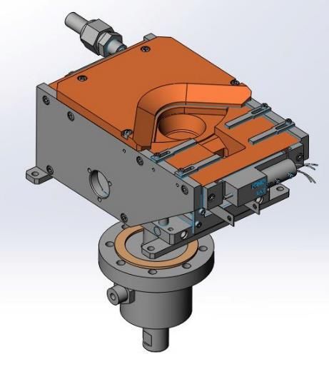
External Reassembly
See supplied pdf drawings and Photos 4-9
Insert fresh o-rings in the feedthru. With the source in place the external parts can be
installed. First the motor clamp with the motor is fixed to the feedthru. Next the gear
clamp and 96 tooth gear are clamped to the feedthru. Then the water union and tube
are inserted. Finally all the water lines are connected.
Photo 4 Attach Magnetic Photo 5 Place EB Source Photo 6 Mount Motor
Seal Feedthrough To in chamber and through Clamp and Gear
Vacuum Chamber Magnetic Seal Feedthrough
Photo 7 Install Water Photo 8 Install Union Strap
Union
25Telemark Model 249/269/279/299 Electron Beam Source Instruction Manual
Quick Check
If necessary use following check list which is used on final Q.A. to make sure everything
is in place.
Emitter Assembly Filament location
Anode, beam former and filament parallel
#6-32 screws snugged
Resistance check Filament continuity
Emitter to ground
Fastened to baseplate
Tightened firmly to
HV leads
Main Body Screws tightened Crucible
Assembly
Emitter
Magnet arms
Magnet shield
Crucible cover plate
Straps
Feedthru
Check magnet orientation!
(From Rear of source, North on left, Top up)
Magnetic Field Checked directly Above filament: Longitudinal
No current, 1 Amp applied
Lateral
Leak check To 2 x 10⁻¹⁰ Std. ccs of helium
Cleanliness Beadblasting
Flakes, dust, coating
Fingerprints
Waterline Fittings Tight
26Telemark Model 249/269/279/299 Electron Beam Source Instruction Manual
KITS AND ACCESSORIES
7
One of the following Installation Kits is shipped with the EB Source.
249-0723-1 Installation Kit, 249, VCR
No. Description Quantity
211-5006-1 Thumbscrew, Crucible 1
244-0090-1 Shunt 2
249-2000-1 Seal Kit, 249, VCR 1
271-4004-1 Four-In-One Screwdriver 1
271-4020-1 Wrench Kit 1
273-0038-1 HV Lead Kit 1
273-0700-3 Emitter Parts Kit 1
249-0723-2 Installation Kit, 249, CFF
No. Description Quantity
211-5006-1 Thumbscrew, Crucible 1
244-0090-1 Shunt 2
249-2000-2 Seal Kit, 249, CFF 1
271-4004-1 Four-In-One Screwdriver 1
271-4020-1 Wrench Kit 1
273-0038-1 HV Lead Kit 1
273-0700-3 Emitter Parts Kit 1
269-1723-4 Installation Kit, 269, VCR
No. Description Quantity
265-0090-1 Shunt 2
269-2000-2 Seal Kit, 269/279,299 VCR 1
271-4004-1 Four-In-One Screwdriver 1
271-4020-1 Wrench Kit 1
271-5006-1 Thumbscrew, Crucible 1
273-0038-1 HV Lead Kit 1
274-0700-1 Emitter Parts Kit, UHV 1
27Telemark Model 249/269/279/299 Electron Beam Source Instruction Manual
269-1723-5 Installation Kit, 269, CFF
No. Description Quantity
265-0090-1 Shunt 2
269-2000-3 Seal Kit, 269/279,299 CFF 1
271-4004-1 Four-In-One Screwdriver 1
271-4020-1 Wrench Kit 1
271-5006-1 Thumbscrew, Crucible 1
273-0038-1 HV Lead Kit 1
274-0700-1 Emitter Parts Kit, UHV 1
279-0723-4 Installation Kit, 279, VCR
No. Description Quantity
269-2000-2 Seal Kit, 269/279,299 VCR 1
271-0090-1 Shunt 1
271-4004-1 Four-In-One Screwdriver 1
271-4020-1 Wrench Kit 1
271-5006-1 Thumbscrew, Crucible 1
273-0038-1 HV Lead Kit 1
274-0700-1 Emitter Parts Kit, UHV 1
279-0723-5 Installation Kit, 279, CFF
No. Description Quantity
269-2000-3 Seal Kit, 269/279,299 CFF 1
271-0090-1 Shunt 1
271-4004-1 Four-In-One Screwdriver 1
271-4020-1 Wrench Kit 1
271-5006-1 Thumbscrew, Crucible 1
273-0038-1 HV Lead Kit 1
274-0700-1 Emitter Parts Kit, UHV 1
299-0723-4 Installation Kit, 299, VCR
No. Description Quantity
269-2000-2 Seal Kit, 269/279,299 VCR 1
271-4004-1 Four-In-One Screwdriver 1
271-4020-1 Wrench Kit 1
271-5006-1 Thumb Screw, Crucible 1
273-0038-1 HV Lead Kit 1
274-0700-2 Emitter Parts Kit 1
294-0090-1 Shunt Bar 1
299-0723-4 Installation Kit, 299, CFF
No. Description Quantity
269-2000-3 Seal Kit, 269/279,299 CFF 1
271-4004-1 Four-In-One Screwdriver 1
271-4020-1 Wrench Kit 1
271-5006-1 Thumb Screw, Crucible 1
273-0038-1 HV Lead Kit 1
274-0700-2 Emitter Parts Kit 1
294-0090-1 Shunt Bar 1
28Telemark Model 249/269/279/299 Electron Beam Source Instruction Manual
Accessories
Recommended parts:
1 Power Supply – We recommend the ST or TT power supplies from Telemark.
However, this source will work well with all available power supplies that meet
the operating specifications of the electron beam source.
2 High Voltage Covers – Install two High Voltage Covers for each EB source.
No. Description
275-0210-1 HV Cover Assy. Single Pass 1”
275-0210-2 HV Cover Assy. Single Pass 1.25”
275-0211-1 HV Cover Assy. Single Pass CFF
3 Indexer – Install one multi-pocket indexer for each EB source.
Model Description
397 Crucible Indexer
4 Flowmeter – This Model uses ¼” NPT fittings and is rated at 1-6 gpm adjustable.
No. Description
271-0831-1 Water Flow Switch, 110V
5 Shutter – For applications requiring a shutter install one of the following.
No. Description
275-0888-1 Shutter/Controller, 1" feedthrough
275-0888-2 Shutter/Controller, 1-1/4" feedthrough
275-0888-3 Shutter/Controller, CFF 2.75"feedthrough
6 Feedthrough Kit – Install one of the following kits for each EB source.
275-0703-1 Feedthru Kit, 1"
No. Description Quantity
275-0001-1 HV Feedthru, 1" 2
275-0003-1 Water Feedthru Assembly, 1" 1
275-0008-1 8 Pin Instrument Feedthru, Octal, 1" 1
275-0703-2 Feedthru Kit, 1.25"
No. Description Quantity
275-0001-2 HV Feedthru, 1.25" 2
275-0003-2 Water Feedthru Assembly, 1.25" 1
275-0008-2 8 Pin Instrument Feedthru, Octal, 1.25" 1
29Telemark Model 249/269/279/299 Electron Beam Source Instruction Manual
275-0703-3 Feedthru Kit, CFF
No. Description Quantity
275-0001-3 HV Feedthru, CFF 2
275-0003-4 Water Feedthru Assembly, 2-3/4 CFF 1
275-0008-3 8 Pin Instrument Feedthru, Octal, CFF 1
Replacement Crucibles
Replacement crucibles are available to replace the crucible or to change number and
size of the crucible pockets. When changing the number of pockets a new cover is
required. In addition to standard crucibles, custom combinations of pocket sizes are
available, please contact the factory.
Model 249 Crucibles
No. Description
249-0240-1 Crucible, 4x 4cc
249-0245-1 Crucible, 4x 7cc
249-0270-1 Crucible, Trough 45cc
249-0281-1 Crucible, 6x 4cc
249-0282-1 Crucible, 6x 7cc
Model 269 Crucibles
No. Description
269-0220-1 Crucible, 4x 25cc
269-0221-1 Crucible, 4x 30cc
269-0245-1 Crucible, 4x 7cc
269-0255-1 Crucible, 6x 15cc
269-0260-1 Crucible, 8x 7cc
269-0266-1 Crucible, 4x 15cc
269-0270-1 Crucible, Trough 190cc
269-0282-1 Crucible, 6x 7cc
Model 279 Crucibles
No. Description
279-0209-1 Crucible, 4x 7cc
279-0210-1 Crucible, 4x 15cc
279-0220-1 Crucible, 4x 25cc
279-0221-1 Crucible, 4x 30cc
279-0227-1 Crucible, 4x 40cc
279-0245-1 Crucible, 6x 7cc
279-0255-1 Crucible, 6x 15cc
279-0257-1 Crucible, 6x 25cc
279-0260-1 Crucible, 8x 7cc
279-0261-1 Crucible, 8x 15cc
279-0270-1 Crucible, Trough, 275cc
30Telemark Model 249/269/279/299 Electron Beam Source Instruction Manual
Rebuild Kits
Seal Kits
249-2000-1 Seal Kit, 249, VCR
No. Description Quantity
231-0456-5 Teflon Ferrell Set 1
271-2014-1 O-Ring, Viton, ID 1/2", W 1/16" 1
271-3500-1 Gasket, VCR 1/4" 2
271-3621-1 Gasket, CFF 4.5" Silver Plated 1
249-2000-2 Seal Kit, 249, CFF
No. Description Quantity
231-0456-5 Teflon Ferrell Set 1
271-2014-1 O-Ring, Viton, ID 1/2", W 1/16" 1
271-3581-1 Gasket, CFF 1.33" Silver Plated 2
271-3621-1 Gasket, CFF 4.5" Silver Plated 1
269-2000-2 Seal Kit, 269/279, VCR
No. Description Quantity
271-2022-1 O-Ring, Viton, ID 1", W 1/16" 2
271-2112-1 O-Ring, Viton, ID 1/2", W 3/32" 1
271-3501-1 Gasket, VCR 3/8"-1/2” 2
271-3601-1 Gasket, CFF 2.75" Silver Plated 1
271-3621-1 Gasket, CFF 4.5" Silver Plated 1
269-2000-3 Seal Kit, 269/279, CFF
No. Description Quantity
271-2022-1 O-Ring, Viton, ID 1", W 1/16" 2
271-2112-1 O-Ring, Viton, ID 1/2", W 3/32" 1
271-3581-1 Gasket, CFF 1.33" Silver Plated 2
271-3601-1 Gasket, CFF 2.75" Silver Plated 1
271-3621-1 Gasket, CFF 4.5" Silver Plated 1
31Telemark Model 249/269/279/299 Electron Beam Source Instruction Manual
Emitter Parts Kit for 273-0150-8 Emitter
273-0700-3 Emitter Parts Kit
No. Description Quantity
271-5003-1 Gloves, pr. 1
271-6010-5 Screw, #6-32 X 1/4" Slot Flat Head,Ti 2
271-6020-5 Screw, #6-32 X 3/16" Ti SHCS 1
271-6030-6 Vented Screw, #6-32 X 1/4" SST SHCS, SILVER 4
271-6050-6 Vented Screw, #6-32 X 3/8" SST SHCS, SILVER 6
271-6060-6 Vented Screw, #6-32 X 1/2" SST SHCS, SILVER 2
271-6242-1 Flat Washer, #6 2
273-0001-1 Filament, 7-1/2 Turn 5
273-0003-1 Anode Plate 1
273-0004-2 Beam Former 1
273-0005-1 Insulator, Cross 1
273-0006-1 Insulator, Collar 2
273-0008-1 Insulator, L 1
273-0010-1 Insulator, HV 2
273-0011-1 HV Shield 2
Emitter Parts Kit for 274-0150-1 Emitter
274-0700-1 Emitter Parts Kit
No. Description Quantity
271-5003-1 Gloves, pr. 1
271-6010-5 Screw, #6-32 X 1/4" Slot Flat Head,Ti 2
271-6020-5 Screw, #6-32 X 3/16" Ti SHCS 1
271-6030-1 Vented Screw, #6-32 X 1/4" SST SHCS 4
271-6040-1 Vented Screw, #6-32 X 5/16" SST SHCS 2
271-6050-1 Vented Screw, #6-32 X 3/8" SST SHCS 4
271-6060-1 Vented Screw, #6-32 X 1/2" SST SHCS 2
271-6242-1 Flat Washer, #6 2
273-0001-1 Filament, 7-1/2 Turn 5
274-0003-7 Anode Plate 1
274-0004-7 Beam Former 1
274-0005-1 Insulator, Cross 1
274-0006-1 Insulator, Collar 2
274-0008-1 Insulator, L 1
274-0010-1 Insulator, HV 2
274-0011-1 HV Shield 2
274-0011-2 HV Shield, Large 2
HV Lead Kit
273-0038-1 HV Lead Kit
No. Description Quantity
119-0010-4 Copper Rod, OFHC, 8awg (0.125" x 12”) 2
110-8404-1 Lug, Crimp Terminal, Ring, 8 Ga., 1/4 2
275-0119-6 Lug, Tin Pltd Copper 8awg #10 Non-Insulated Ring 2
271-6150-9 Screw, #10-32 X 1/2" SST SHCS 2
271-6255-1 Nut, #10-32, SST 2
271-6245-1 Flat Washer, #10, SST 4
32Telemark Model 249/269/279/299 Electron Beam Source Instruction Manual
TROUBLESHOOTING
8
This section should be read in conjunction with the section on assembling the emitter.
Experience demonstrates that the emitter assembly causes ninety percent of system
problems in production.
Power Problems
Problem: EMISSION CURRENT MUST BE TURNED TO HIGHER THAN
NORMAL TO EVAPORATE.
Cause: Filament is badly warped or was put in backwards.
Correction: Remove emitter assembly and replace filament.
Problem: EMISSION GOES TO MAXIMUM WHEN THE HIGH VOLTAGE IS
TURNED ON.
Cause: A flake of material (sometimes extremely small) may be shorting the filament
block to the anode plate. This happens occasionally when heating brittle materials too
fast.
Correction: Remove emitter, and try to locate and remove flake.
Problem: NO EMISSION CURRENT.
Cause 1: Filament is broken or leads need tightening
Correction: Replace filament or tighten connections.
Cause 2: Power supply filament control circuit is faulty. parallel
33Telemark Model 249/269/279/299 Electron Beam Source Instruction Manual
Correction: Fix power supply.
Problem: NO VOLTAGE.
Cause: System or source has high resistance ground
Correction: Check emitter, filament, and feedthroughs for shorts.
Beam Problems
Problem: NO BEAM VISIBLE IN CRUCIBLE AS CURRENT IS INCREASED.
Cause 1: The magnet was reversed when reassembling the source (this can have
damaging affects on the EB source and chamber walls if emission current is increased
too far while searching for beam).
Correction: Close down the system and reassemble the source with the magnet
properly oriented.
Cause 2: The sweep unit may have a problem.
Correction: Check sweep for proper setup.
Problem: THE BEAM IS CENTERED TO THE FRONT OF THE CRUCIBLE,
WITH NO COIL CURRENT.
Cause 1: The high voltage is below what the source was gaussed for.
Correction: Adjust the voltage so the beam is centered.
Cause 2: The magnet is too strong.
Correction: Place a shunt just behind the cover plate on the magnet arms to
weaken the magnet.
Problem: THE BEAM CENTERED TO THE BACK OF THE CRUCIBLE,
WITH NO COIL CURRENT.
Cause 1: The high voltage is above what the source was gaussed for.
Correction: Adjust the voltage so the beam is centered.
34Telemark Model 249/269/279/299 Electron Beam Source Instruction Manual
Cause 2: The magnet is too weak.
Correction: Remove shunts. If still out of position, contact factory to have the
source regaussed.
Problem: THE BEAM DOES NOT HAVE THE DESIRED SHAPE.
Cause 1: The filament is warped or misaligned.
Correction: Replace the filament.
Cause 2: The pole pieces are either in or out too far.
Correction: Adjust the pole pieces.
Cause 3: The voltage is not set correctly causing the beam to spread out.
Correction: Adjust the voltage.
Problem: ARCING AND BLUE FLUORESCENCE OCCUR WHERE THE
BEAM SHOULD BE.
Cause: The pressure is too high. There may be a water leak, the bleed valve may be
wide open, or chamber seal may be broken.
Correction: Shut off the bleed valve, check the source or water fittings for leaks,
check the most recently opened chamber seals (such as the door) for clean
surfaces. Mentally and, if necessary, physically leak check chamber.
Rotation Problems
Possible problems with Quad-ring sealed Multi-Pocket Sources.
Problem: LOSS OF VACUUM WHEN THE CRUCIBLE IS ROTATED.
Cause: Water seal is letting water through.
Correction: Install a new Quad-ring.
Problem: THE CRUCIBLE IS DIFFICULT TO ROTATE.
Cause 1: The water seal is in need of lubrication.
Correction: Install a new Quad-ring.
35Telemark Model 249/269/279/299 Electron Beam Source Instruction Manual Cause 2: The drive bearing is bad. Correction: Check and replace bearing if needed. 36
You can also read