LAMBORGHINI HURACÁN GT3 EVO - USER MANUAL - iRacing
←
→
Page content transcription
If your browser does not render page correctly, please read the page content below
LAMBORGHINI HURACÁN GT3 EVO
USER MANUAL

                              1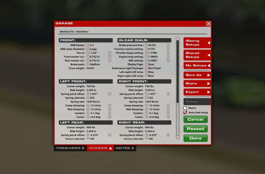
Table of Contents
CLICK TO VIEW A SECTION

 GENERAL INFORMATION

 A Message From iRacing »3
 Tech Specs »4
 Introduction »5
        Getting Started »5
        Loading An iRacing Setup »6
 Dash Pages »7
        Day »7
        Night »8
        Magnus Qual »                                                          9
        Qual »                                                                 10
        Pit Limiter »                                                          11
        Shift Lights »                                                         11

 ADVANCED SETUP OPTIONS

 Tires & Aero »12
        Tire Settings »12
        Aerodynamics »                                                         13
 Chassis »15
        Front End »15
        In-Car Dials »17
        Front Corners »19
        Rear Corners »21
        Rear End »22

                          L AMBORGHINI HUR AC ÁN G T3 E VO   |   USER M ANUAL        2
DE AR iR ACING USER,
Congratulations on your purchase of the Lamborgini Huracán GT3 EVO! From all of us at iRacing, we
appreciate your support and your commitment to our product. We aim to deliver the ultimate sim racing
experience, and we hope that you’ll find plenty of excitement with us behind the wheel of your new car!
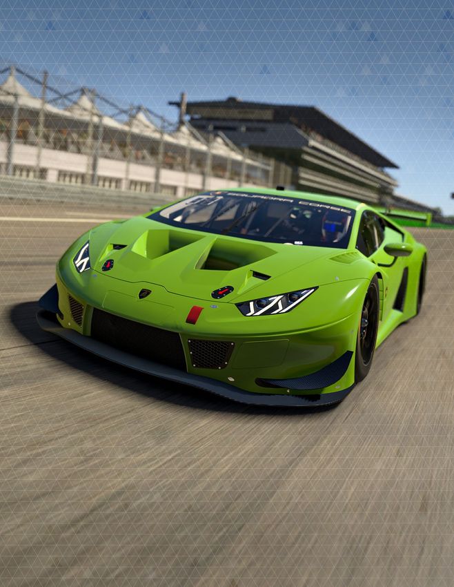
Years of racing heritage come together in the Lamborghini Huracán GT3 EVO, Lamborghini’s latest GT3
challenger in sports car racing series from around the world. Developed in house in Sant’Agata Bolognese
by Lamborghini Squadra Corse, the Huracán GT3 EVO builds on the winning formula of its predecessor, the
Huracán GT3, with improved aerodynamics developed in conjunction with Dallara and a powerful 5.2-liter
V10 engine.
2020 was a banner year for the car, with a clean sweep of the IMSA WeatherTech SportsCar
Championship’s driver and team titles in both its full-season and endurance race standings for Paul Miller
Racing. Across the Atlantic, Barwell Motorsport ran the car to Lamborghini’s first British GT title, while a
class victory in the 24 Hours of Spa and multiple GT World Challenge victories rounded out a stellar season.
The following guide explains how to get the most out of your new car, from how to adjust its settings off of
the track to what you’ll see inside of the cockpit while driving. We hope that you’ll find it useful in getting up
to speed.
Thanks again for your purchase, and we’ll see you on the track!
3
LAMBORGHINI HURACÁN GT3 EVO             |    TECH SPECS

CHASSIS
ALUMINUM UNIBODY
C ONS T RUC T ION W I T H
C ARBON FIBRE BODY WORK

FRONT AND REAR DOUBLE
A-ARMS WITH COILOVERS;             LENGTH         WIDTH             WHEELBASE         DRY WEIGHT
                                                                                                          WET WEIGHT
                                                                                                          WITH DRIVER
OHLINS TTX-36 2-WAY
ADJUSTABLE DAMPERS; BLADE-      4550mm          2220mm              2645mm            1285kg              1411kg
                                   179.2in        87.4in             104.2in           2732lbs             3111lbs
ADJUSTABLE FRONT AND REAR
ANTI-ROLL BARS

POWER
UNIT
5.2 LITER V10

                                                     DISPLACEMENT         RPM LIMIT              TORQUE              POWER

                                                     5.2Liters           8500RPM            400lb-ft             500bhp
                                                           317CID                                545Nm               374kW

                             L AMBORGHINI HUR AC ÁN G T3 E VO        |   USER M ANUAL                                        4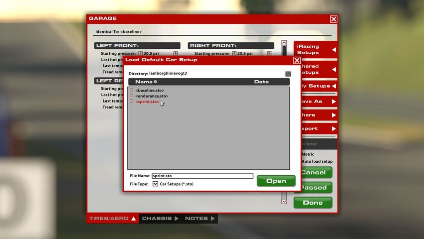
LAMBORGHINI HURACÁN GT3 EVO                       |   INTRODUCTION

Introduction
The information found in this guide is intended to provide a deeper understanding of the
chassis setup adjustments available in the garage, so that you may use the garage to tune
the chassis setup to your preference.

Before diving into chassis adjustments, though, it is best to become familiar with the car
and track. To that end, we have provided baseline setups for each track commonly raced
by these cars. To access the baseline setups, simply open the Garage, click iRacing Setups,
and select the appropriate setup for your track of choice. If you are driving a track for which
a dedicated baseline setup is not included, you may select a setup for a similar track to use
as your baseline. After you have selected an appropriate setup, get on track and focus on
making smooth and consistent laps, identifying the proper racing line and experiencing tire
wear and handling trends over a number of laps.

Once you are confident that you are nearing your driving potential with the included baseline
setups, read on to begin tuning the car to your handling preferences.

GETTING STARTED

Before starting the car, it is recommended to map controls for Brake Bias, Traction Control and ABS adjustments. While this is
not mandatory to drive the car this will allow you to make quick changes to the driver aid systems to suit your driving style while
out on the track.
Once you load into the car, getting started is as easy as selecting the upshift button to put it into gear, and hitting the accelerator
pedal. This car uses a sequential transmission and does not require a clutch input to shift in either direction; the car’s downshift
protection will not allow you to downshift if it feels you are traveling too fast for the gear selected and would incur engine damage.
If that is the case, the gear change command will simply be ignored.
Upshifting is recommended when the shift lights on the dashboard are fully illuminated in blue. This is at approximately 8000 rpm.

                                    L AMBORGHINI HUR AC ÁN G T3 E VO           |   USER M ANUAL                                           5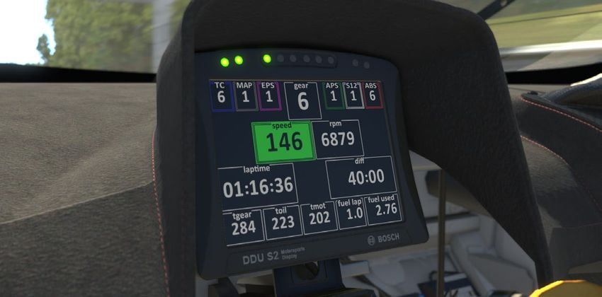
LAMBORGHINI HURACÁN GT3 EVO                       |   INTRODUCTION

LOADING AN iRACING SETUP

When you first load into a session, the iRacing Baseline setup will be automatically loaded onto the car. If you would like to try any
of the other iRacing pre-built options, you may select it by going to Garage > iRacing Setups > and then selecting another option
that fits your needs. Because this car uses slightly different chassis and body configurations on different types of tracks, it will
be necessary to load a setup from the same track type to pass tech inspection. For example, a setup for Talladega will pass at
Daytona, but likely will not pass at Bristol.
If you would like to customize the setup, simply make the changes in the garage that you would like to update and click apply. If
you would like to save your setup for future use click “Save As” on the right to name and save the changes. To access all of your
personally saved setups, click “My Setups” on the right side of the garage. If you would like to share a setup with another driver or
everyone in a session, you can select “Share” on the right side of the garage to do so. If a driver is trying to share a setup with you,
you will find it under “Shared Setups” on the right side of the garage as well.

                                    L AMBORGHINI HUR AC ÁN G T3 E VO           |   USER M ANUAL                                            6
LAMBORGHINI HURACÁN GT3 EVO          |   DASH PAGES

Dash Pages
DAYLIGHT

TOP LEFT			             Current traction control setting (illuminates blue when TC is active)
2ND FROM TOP LEFT		     Currently engine map setting
3RD FROM TOP LEFT       EPS setting, this is not changeable
TOP CENTER			           Currently selected gear
3RD FROM TOP RIGHT		    APS setting, this is not changeable
2ND FROM TOP RIGHT		    S12 setting, this is not changeable
TOP RIGHT			            Current ABS setting (illuminates blue when ABS is active)
CENTER TOP LEFT		       Road speed (km/h or mph)
CENTER TOP RIGHT        Engine rpm
CENTER BOTTOM LEFT		    Current lap time
CENTER BOTTOM RIGHT     Difference to best lap time
BOTTOM LEFT			          Gearbox oil temperature (Celsius or Fahrenheit)
2ND FROM BOTTOM LEFT    Engine oil temperature (Celsius or Fahrenheit)
BOTTOM CENTER		         Engine water temperature (Celsius or Fahrenheit)
2ND FROM BOTTOM RIGHT   Fuel used this lap (Litres or US Gallons)
BOTTOM RIGHT			         Fuel used this stint (Litres or US Gallons)

                        L AMBORGHINI HUR AC ÁN G T3 E VO              |   USER M ANUAL          7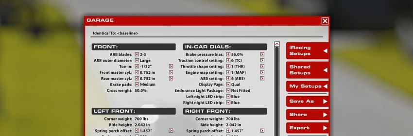
LAMBORGHINI HURACÁN GT3 EVO          |   DASH PAGES

NIGHT TIME

TOP LEFT			             Current traction control setting (illuminates blue when TC is active)
2ND FROM TOP LEFT       Current engine map setting
3RD FROM TOP LEFT		     EPS setting, this is not changeable
TOP CENTER			           Currently selected gear
3RD FROM TOP RIGHT		    APS setting, this is not changeable
2ND FROM TOP RIGHT		    S12 setting, this is not changeable
TOP RIGHT			            Current ABS setting (illuminates blue when ABS is active)
CENTER TOP LEFT		       Road speed (km/h or mph)
CENTER TOP RIGHT		      Engine rpm
CENTER BOTTOM LEFT		    Current lap time
CENTER BOTTOM RIGHT     Difference to best lap time
BOTTOM LEFT			          Gearbox oil temperature (Celsius or Fahrenheit)
2ND FROM BOTTOM LEFT    Engine oil temperature (Celsius or Fahrenheit)
BOTTOM CENTER		         Engine water temperature (Celsius or Fahrenheit)
2ND FROM BOTTOM RIGHT   Fuel used this lap (Litres or US Gallons)
BOTTOM RIGHT			         Fuel used this stint (Litres or US Gallons)

                        L AMBORGHINI HUR AC ÁN G T3 E VO              |   USER M ANUAL          8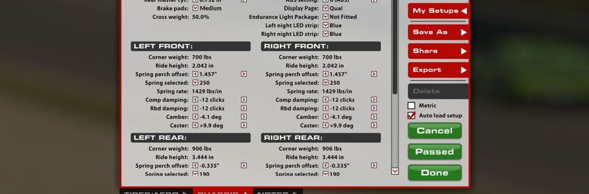
LAMBORGHINI HURACÁN GT3 EVO            |   DASH PAGES

MAGNUS QUALIFYING

TOP LEFT					Current traction control setting (illuminates blue when TC is active)
2ND FROM TOP LEFT				                      Current engine map setting
3RD FROM TOP LEFT				                      EPS setting, this is not changeable
TOP CENTER					Engine rpm
3RD FROM TOP RIGHT				                     Current throttle map setting
2ND FROM TOP RIGHT				                     FUNC setting, this is not changeable
TOP RIGHT					Current ABS setting (illuminates blue when ABS is active)
ABSOLUTE CENTER				Currently selected gear
CENTER TOP LEFT				                        Current lap time
CENTER TOP MIDDLE GREEN BOX		              Current road speed (km/h or mph)
CENTER TOP RIGHT				                       Difference to best lap time
CENTER MID LEFT BLUE BOX			                LF tire pressure (bar or psi)
CENTER CENTER TOP LEFT GREEN BOX		         LF tire temperature (Celsius or Fahrenheit)
CENTER CENTER TOP RIGHT GREEN BOX          RF tire temperature (Celsius or Fahrenheit)
CENTER MID RIGHT BLUE BOX			               RF tire pressure (bar or psi)
CENTER MID LEFT GREEN BOX			               LR tire pressure (bar or psi)
CENTER CENTER BOTTOM LEFT GREEN BOX        LR tire temperature (Celsius or Fahrenheit)
CENTER CENTER BOTTOM RIGHT GREEN BOX RR tire temperature (Celsius or Fahrenheit)
CENTER MID RIGHT GREEN BOX		               RR tire pressure (bar or psi)
BOTTOM LEFT					Gearbox oil temperature (Celsius or Fahrenheit)
2ND FROM BOTTOM LEFT			                    Engine oil temperature (Celsius or Fahrenheit)
2ND FROM BOTTOM RIGHT			                   Engine water temperature (Celsius or Fahrenheit)
BOTTOM RIGHT					Fuel used this stint (Litres or US Gallons)

                             L AMBORGHINI HUR AC ÁN G T3 E VO      |     USER M ANUAL         9
LAMBORGHINI HURACÁN GT3 EVO         |   DASH PAGES

QUALIFYING

TOP LEFT				Current traction control setting (illuminates blue when TC is active)
2ND FROM TOP LEFT			            Current engine map setting
3RD FROM TOP LEFT			            EPS setting, this is not changeable
TOP CENTER				Engine rpm
3RD FROM TOP RIGHT			           APS setting, this is not changeable
2ND FROM TOP RIGHT			           S12 setting, this is not changeable
TOP RIGHT				Current ABS setting (illuminates blue when ABS is active)
CENTER TOP LEFT			              Current lap time
CENTER CENTER			                Road speed (km/h or mph)
CENTER TOP RIGHT			             Difference to best lap time
ABSOLUTE CENTER			              Currently selected gear
CENTER LEFT BLUE BOX		          LF tire pressure (bar or psi)
CENTER RIGHT BLUE BOX		         RF tire pressure (bar or psi)
CENTER BOTTOM LEFT GREEN BOX    LR tire pressure (bar or psi)
CENTER BOTTOM RIGHT GREEN BOX   RR tire pressure (bar or psi)
BOTTOM				Delta bar to best lap time

                         L AMBORGHINI HUR AC ÁN G T3 E VO       |     USER M ANUAL   10
LAMBORGHINI HURACÁN GT3 EVO | DASH PAGES
PIT LIMITER
When the pit limiter is active a large blue box displays across the dashboard along with the center 6 shift light LEDs flashing blue.
SHIFT LIGHTS
1 GREEN 6650 rpm
2 GREEN 6800 rpm
3 GREEN 6950 rpm
4 GREEN 7100 rpm
1 YELLOW 7250 rpm
2 YELLOW 7400 rpm
1 RED 7550 rpm
2 RED 7700 rpm
3 RED 7850 rpm
ALL BLUE 8000 rpm
L AMBORGHINI HUR AC ÁN G T3 E VO | USER M ANUAL 11LAMBORGHINI HURACÁN GT3 EVO | ADVANCED SETUP OPTIONS | TIRES & AERO
ADVANCED SETUP OPTIONS
This section is aimed toward more advanced users who want to dive deeper into the different aspects
of the vehicle’s setup. Making adjustments to the following parameters is not required and can lead to
significant changes in the way a vehicle handles. It is recommended that any adjustments are made in
an incremental fashion and only singular variables are adjusted before testing changes.
Tires & Aero
TIRE SETTINGS (ALL FOUR TIRES)
C OLD AIR PRES SURE
This represents the amount of air pressure used to inflate the tire when car is loaded into the world. Higher pressures will reduce
rolling drag and heat buildup, but will decrease grip. Lower pressures will increase rolling drag and heat buildup, but will increase
grip. Higher speeds and loads require higher pressures, while lower speeds and loads will see better performance from lower
pressures. Cold pressures should be set to track characteristics for optimum performance. Generally speaking, it is advisable to
start at lower pressures and work your way upwards as required.
L AMBORGHINI HUR AC ÁN G T3 E VO | USER M ANUAL 12LAMBORGHINI HURACÁN GT3 EVO | ADVANCED SETUP OPTIONS | TIRES & AERO
HO T AIR PRES SURE
This represents the amount of air pressure present in the tire after the car has returned to the pits. The difference between cold
and hot pressures can be used to identify how the car is progressing through a run in terms of balance, with heavier-loaded tires
seeing a larger difference between cold and hot pressures. Ideally, tires that are worked in a similar way should build pressure
at the same rate to prevent a change in handling balance over the life of the tire, so cold pressures should be adjusted to ensure
that similar tires are at similar pressures once up to operating temperature. Hot pressures should be analysed once the tires
have stabilised after a period of laps. As the number of laps per run will vary depending upon track length a good starting point is
approximately 50% of a full fuel run.
T IRE T EMPER AT URES
This represents the tire carcass temperatures (measured via Pyrometer) once the car has returned to the pits. Wheel Loads and
the amount of work a tire is doing on-track is reflected in the tire’s temperature, and these values can be used to analyze the car’s
handling balance. Center temperatures are useful for directly comparing the work done by each tire, while the Inner and Outer
temperatures are useful for analyzing the wheel alignment (predominantly camber) while on track. These values are measured in
three zones across the tread of the tire. Inside, middle and Outer.
T RE AD REM AINING
The amount of tread remaining on the tire once the car has returned from the pits. Tire wear is very helpful in identifying
any possible issues with alignment, such as one side of the tire wearing excessively, and can be used in conjunction with tire
temperatures to analyze the car’s handling balance. These values are measured in the same zones as those of temperature.
AERODYNAMICS
W ING SE T T ING
The wing setting refers to the relative angle of attack of the rear wing; this is a powerful aerodynamic device which has a
significant impact upon the total downforce (and drag!) produced by the car, as well as shifting the aerodynamic balance of the car
rearwards with increasing angle. Increasing the rear wing angle results in more total cornering grip capability in medium to high
speed corners but will also result in a reduction of straight line speed. Rear wing angle should be adjusted in conjunction with front
and rear ride heights, specifically the difference between front and rear ride heights known as “rake”. To retain the same overall
aerodynamic balance it is necessary to increase the rake of the car when increasing the rear wing angle.
AERO C AL CUL AT OR
This calculator is a reference tool ONLY. The Aero Calculator is a tool provided to aid in understanding the shift in aerodynamic
balance associated with adjustment of the rear wing setting and front and rear ride heights. It is important to note that the values
for front and rear ride height displayed here DO NOT result in any mechanical changes to the car itself, however, changes to the
rear wing angle here WILL be applied to the car.
L AMBORGHINI HUR AC ÁN G T3 E VO | USER M ANUAL 13LAMBORGHINI HURACÁN GT3 EVO | ADVANCED SETUP OPTIONS | TIRES & AERO
FRON T RH AT SPEED
The Ride Height (RH) at Speed is used to give the Aero Calculator heights to reference for aerodynamic calculations. When using
the aero calculator, determine the car’s Front Ride height via telemetry at any point on track and input that value into the “Front
RH at Speed” setting. It is advisable to use an average value of the LF and RF ride heights as this will provide a more accurate
representation of the current aero platform rather than using a single corner height.
RE AR RH AT SPEED
The Ride Height (RH) at Speed is used to give the Aero Calculator heights to reference for aerodynamic calculations. When using
the aero calculator, determine the car’s Rear Ride height via telemetry at any point on track and input that value into the “Front
RH at Speed” setting. It is advisable to use an average value of the LR and RR ride heights as this will provide a more accurate
representation of the current aero platform rather than using a single corner height.
FRON T DOW NFORCE
This value displays the proportion of downforce acting at the front axle for the given wing and ride height combination set within
the calculator parameters. This value is an instantaneous representation of your aero balance at this exact set of parameters and
it can be helpful to pick multiple points around a corner or section of track to understand how the aerodynamic balance is moving
in differing situations such as braking, steady state cornering and accelerating at corner exit. A higher forwards percentage will
result in more oversteer in mid to high speed corners.
L AMBORGHINI HUR AC ÁN G T3 E VO | USER M ANUAL 14LAMBORGHINI HURACÁN GT3 EVO | ADVANCED SETUP OPTIONS | CHASSIS
Chassis
FRONT END
ARB BL ADES
The configuration of the Anti-Roll Bar arms, or “blades”, can be changed to alter the overall stiffness of the ARB assembly. Higher
values transfer more force through the arms to the ARB itself, increasing roll stiffness in the front suspension and producing
the same effects, albeit on a smaller scale, as increasing the diameter of the sway bar. Conversely, lower values reduce the
roll stiffness of the front suspension and produce the same effects as decreasing the diameter of the sway bar. These blade
adjustments can be thought of as fine-tuning adjustments between sway bar diameter settings. 6 ARB blade options are available
ranging from 1-1 (softest) to 3-3 (stiffest).
ARB OU T ER DI AME T ER
The ARB (Anti-Roll Bar) size influences the stiffness of the front suspension in roll, such as when navigating a corner. Increasing
the ARB size will increase the roll stiffness of the front suspension, resulting in less body roll but increasing mechanical understeer.
This can also, in some cases, lead to a more responsive steering feel from the driver. Conversely, reducing the ARB size will
soften the suspension in roll, increasing body roll but decreasing mechanical understeer. This can result in a less-responsive feel
from the steering, but grip across the front axle will increase. 4 configurations of ARB diameter are available and range from
disconnected (softest) to large (stiffest).
L AMBORGHINI HUR AC ÁN G T3 E VO | USER M ANUAL 15LAMBORGHINI HURACÁN GT3 EVO | ADVANCED SETUP OPTIONS | CHASSIS
T OE -IN
Toe is the angle of the wheel, when viewed from above, relative to the centerline of the chassis. Toe-in is when the front of the
wheel is closer to the centerline than the rear of the wheel, and Toe-out is the opposite. On the front end, adding toe-out will
increase slip in the inside tire while adding toe-in will reduce the slip. This can be used to increase straight-line stability and turn-in
responsiveness with toe-out. Toe-in at the front will reduce turn-in responsiveness but will reduce temperature buildup in the front
tires.
FRON T M AS T ER CYLINDER
The Front Brake Master Cylinder size can be changed to alter the line pressure to the front brake calipers. A larger master
cylinder will reduce the line pressure to the front brakes, this will shift the brake bias rearwards and increase the pedal effort
required to lock the front wheels. A smaller master cylinder will do the opposite and increase brake line pressure to the front
brakes, shifting brake bias forward and reducing required pedal effort. 7 Different master cylinder options are available ranging
from 15.9 mm / 0.626” (highest line pressure) to 23.8 mm / 0.937” (lowest line pressure).
RE AR M AS T ER CYLINDER
The Rear Brake Master Cylinder size can be changed to alter the line pressure to the rear brake calipers. A larger master cylinder
will reduce the line pressure to the rear brakes, this will shift the brake bias forwards and increase the pedal effort required to
lock the rear wheels. A smaller master cylinder will do the opposite and increase brake line pressure to the rear brakes, shifting
brake bias rearward and reducing required pedal effort. 7 Different master cylinder options are available ranging from 15.9 mm /
0.626” (highest line pressure) to 23.8 mm / 0.937” (lowest line pressure).
BR AK E PADS
The vehicle’s braking performance can be altered via the Brake Pad Compound. The “Low” setting provides the least friction,
reducing the effectiveness of the brakes, while “Medium” and “High” provide more friction and increase the effectiveness of the
brakes while increasing the risk of a brake lockup.
CROS S W EIGH T
The percentage of total vehicle weight in the garage acting across the right front and left rear corners. 50.0% is generally optimal
for non-oval tracks as this will produce symmetrical handling in both left and right hand corners providing all other chassis settings
are symmetrical. Higher than 50% cross weight will result in more understeer in left hand corners and increased oversteer in
right hand corners, cross weight can be adjusted by making changes to the spring perch offsets at each corner of the car.
L AMBORGHINI HUR AC ÁN G T3 E VO | USER M ANUAL 16LAMBORGHINI HURACÁN GT3 EVO | ADVANCED SETUP OPTIONS | CHASSIS
IN-CAR DIALS
BR AK E PRES SURE BI AS
Brake Bias is the percentage of braking force that is being sent to the front brakes. Values above 50% result in more pressure
being sent to the front master cylinder, while values less than 50% send more force to the rear master cylinder. This should be
tuned for both driver preference and track conditions to get the optimum braking performance for a given situation. It is important
to note that differing combinations of master cylinder size will necessitate differing brake pressure bias values, this is because
increasing or reducing the split in master cylinder size difference between front and rear axles will produce an inherent forward or
rearward bias in brake line pressure.
T R AC T ION C ON T ROL SE T T ING
The position of the traction control switch determines how aggressively the ecu cuts engine torque in reaction to rear wheel spin.
12 positions are available but only 10 maps exist. Settings 1-10 range from least intervention/sensitivity (position 1) through
to highest intervention/sensitivity (position 10). Position 11 is the same as position 10 and position 12 disables the traction
control completely. Positions 3 and 4 are the manufacturer recommended baseline settings. More intervention will result in
less wheelspin and less rear tire wear but can reduce overall performance if the traction control is cutting engine torque too
aggressively and stunting corner exit acceleration.
T HRO T T LE SH APE SE T T ING
Throttle shape setting refers to how changes in the drivers pedal position result in changes in provided engine torque. 3 positions
exist, position 1 results in a linear torque map relative to throttle position (e.g. 10% throttle position results in 10% engine torque,
50% throttle position results in 50% engine torque and so on.). Position 3 emulates a non-linear S shaped map similar to a cable
throttle which results in reduced fidelity in the middle portion of the throttle range. Position 2 is a hybrid of position 1 and 3
throttle mapping styles.
ENGINE M AP SE T T ING
The fuel map on which the car is currently running. Position 1 is the base map and produces maximum power but the most fuel
usage. Positions 2 through 11 are for fuel saving under green flag conditions and will reduce engine power output correspondingly.
The higher the number the better the fuel economy but the lower the power output. Position 12 is for saving fuel under safety car
conditions and is not recommended for normal usage.
L AMBORGHINI HUR AC ÁN G T3 E VO | USER M ANUAL 17LAMBORGHINI HURACÁN GT3 EVO | ADVANCED SETUP OPTIONS | CHASSIS
A B S SE T T ING
The current ABS map the car is running. Similar to the traction control setting, 12 positions are available but only 10 maps exist.
Position 1 has the least intervention/support while position 10 has the most support. Position 11 is the same as position 10
and position 12 disables the ABS completely. Positions 4 is the manufacturer recommended baseline setting. More intervention
reduces the possibility of and the duration of lockups during braking but can result in longer braking distances if the system is set
overly aggressive for the amount of available grip.
DISPL AY PAGE
Currently displayed in-car dashboard page. 4 display options are present with 2 options intended for race situations of day and
night and 2 for qualifying. The race options are identical in terms of displayed information but with differing background colour
while the qualifying options are similar in style but display different information.
ENDUR ANCE LIGH T PACK AGE
This setting determines if the car is fitted with an additional
light bar on the nose for increased light output during night
races.
LEF T NIGH T LED S T RIP
Changes the colour of the light strip on the left side of the
car. 7 options are available: Blue, Purple, Red, Yellow, Orange,
Green and Off.
RIGH T NIGH T LED S T RIP
Changes the colour of the light strip on the right side of the
car. 7 options are available: Blue, Purple, Red, Yellow, Orange,
Green and Off.
L AMBORGHINI HUR AC ÁN G T3 E VO | USER M ANUAL 18LAMBORGHINI HURACÁN GT3 EVO | ADVANCED SETUP OPTIONS | CHASSIS
FRONT CORNERS
C ORNER W EIGH T
The weight underneath each tire under static conditions in the garage. Correct weight arrangement around the car is crucial for
optimizing a car for a given track and conditions. Individual wheel weight adjustments and crossweight adjustments are made via
the spring perch offset adjustments at each corner.
FRON T RIDE HEIGH T
Distance from ground to a reference point on the chassis. Since these values are measured to a specific reference point on the
car, these values may not necessarily reflect the vehicle’s ground clearance, but instead provide a reliable value for the height of
the car off of the race track at static values. Adjusting Ride Heights is key for optimum performance, as they can directly influence
the vehicle’s aerodynamic performance as well as mechanical grip. Increasing front ride height will decrease front downforce
as well as decrease overall downforce, but will allow for more weight transfer across the front axle when cornering. Conversely,
reducing ride height will increase front and overall downforce, but reduce the weight transfer across the front axle. Minimum legal
front ride height is 50.0 mm.
SPRING PERCH OFF SE T
Used to adjust the ride height at this corner of the car by changing the installed position of the spring. Increasing the spring perch
offset will result in lowering this corner of the car while reducing the spring perch offset will raise this corner of the car. These
changes should be kept symmetrical across the axle (left to right) to ensure the same corner ride heights and no change in cross
weight. The spring perch offsets can also be used in diagonal pairs (LF to RR and RF to LR) to change the static cross weight in
the car.
SPRING SELEC T ED/SPRING R AT E
This setting determines the installed corner spring stiffness. Stiffer springs will result in a smaller variance in ride height between
high and low load cases and will produce superior aerodynamic performance through improved platform control however, they
will also result in increased tire load variation which will manifest as a loss in mechanical grip. Typically the drawbacks of stiffer
springs will become more pronounced on rougher tracks and softer springs in these situations will result in increased overall
performance. Corner spring changes will influence both roll and pitch control of the platform and ARB changes should be
considered when altering corner spring stiffnesses in order to retain the same front to rear roll stiffness and overall balance.
When reducing corner spring stiffness the ARB stiffness (either via blade or diameter depending on the size of the corner spring
change) should be increased to retain the same roll stiffness as previously. 6 options for spring rate are available ranging from
L AMBORGHINI HUR AC ÁN G T3 E VO | USER M ANUAL 19LAMBORGHINI HURACÁN GT3 EVO | ADVANCED SETUP OPTIONS | CHASSIS
160 N/mm (914 lbs/in) to 280 N/mm (1600 lbs/in). The first portion of the range from 160 N/mm (914 lbs/in) to 250 N/
mm (1429 lbs/in) is in 30 N/mm (172 lbs/in) steps for coarse adjustment while the final 3 rates are stepped in 15 N/mm (86
lbs/in) steps for fine adjustment. Spring perch offsets must be adjusted to return the car to the prior static ride heights after any
spring rate change.
C OMPRES SION DAMPING
The compression damping setting is a paired adjustment controlling both the low and high speed damping characteristics
of the damper. In this case -24 is minimum damping (least resistance to compression) while 0 is maximum damping (most
resistance to compression). Increasing the compression damping will result in a faster transfer of weight to this corner of the
car during transient movements such as braking and direction change with increased damping usually providing an increase in
turn-in response but a reduction in overall grip in the context of front dampers. High speed compression damping will increase
proportionally to the increase in low speed compression damping which will also result in harsher response to kerb strikes. At
smoother tracks more compression damping will typically increase performance while at rougher tracks or ones with aggressive
kerbs less compression damping can result in an increase in mechanical grip at the expense of platform control.
REBOUND DAMPING
The Rebound damping setting is a paired adjustment to both low and high speed rebound damping characteristics. Increasing
rebound damping will slow down the rate at which the damper extends in both low and high speed situations. A typical low damper
speed situation would be as the car rolls back to level on a corner exit while a high speed situation would be where the suspension
is extending after large kerb contact. -24 is minimum damping (least resistance to extension) while 0 is maximum damping (most
resistance to extension). While high rebound stiffness will result in improved platform control for aerodynamic performance and
overall chassis response it is important to avoid situations where the shock is too slow in rebounding as this will result in the tire
losing complete contact with the track surface which can induce or exacerbate severe oscillations.
C AMBER
Camber is the vertical angle of the wheel relative to the center of the chassis. Negative camber is when the top of the wheel is
closer to the chassis centerline than the bottom of the wheel, positive camber is when the top of the tire is farther out than the
bottom. Due to suspension geometry and corner loads, negative camber is desired on all four wheels. Higher negative camber
values will increase the cornering force generated by the tire, but will reduce the amount of longitudinal grip the tire will have
under braking. Excessive camber values can produce very high cornering forces but will also significantly reduce tire life, so it is
important to find a balance between life and performance. Increasing front camber values will typically result in increased front
axle grip during mid to high speed cornering but will result in a loss of braking performance and necessitate a rearward shift in
brake bias to compensate.
C AS T ER
Caster is the vertical angle of the steering axis relative to the side view of the chassis. Positive caster angle is where the steering
axis is leaned rearwards from this viewpoint, the more caster the larger the total trail of the contact patch behind the steering
axis. More caster angle will result in the mechanical trail being a larger proportion of the felt steering weight relative to the tires
pneumatic trail. This will result in a heavier overall steering feel but a possible loss in felt feedback from the tire. Increasing caster
angle will also have secondary effects such as an increase in dynamic camber when turning the wheel through large steering
angles which can be beneficial in chicances or hairpins. As well as this the more caster angle the greater the jacking effect during
cornering which will result in lifting the inside front wheel while lowering the outside front wheel. This jacking effect will also result
in the unloading and potentially lifting of the inside rear wheel which can aid in rotation around tight corners.
L AMBORGHINI HUR AC ÁN G T3 E VO | USER M ANUAL 20LAMBORGHINI HURACÁN GT3 EVO | ADVANCED SETUP OPTIONS | CHASSIS
REAR CORNERS
RE AR RIDE HEIGH T
Distance from ground to a reference point on the rear of the chassis. Increasing rear ride height will decrease rear downforce
as well as increase overall downforce and will allow for more weight transfer across the rear axle when cornering. Conversely,
reducing ride height will increase rear downforce percentage but reduce overall downforce while reducing the weight transfer
across the rear axle. Rear ride height is a critical tuning component for both mechanical and aerodynamic balance considerations
and static rear ride heights should be considered and matched to the chosen rear corner springs for optimal performance.
Minimum legal rear ride height is 50.0 mm while maximum legal rear ride height is 90.0 mm.
SPRING SELEC T ED/SPRING R AT E
Similar to at the front axle, stiffer springs will result in a smaller variance in ride height between high and low load cases and will
produce superior aerodynamic performance through improved platform control at the expense of mechanical grip. This can be
particularly prominent when exiting slow speed corners with aggressive throttle application. Stiffer springs will tend to react
poorly during these instances especially so on rough tracks which will result in significant traction loss. Spring stiffness should
be matched to the needs of the racetrack and set such that the handling balance is consistent between high and low speed
cornering. As an example case, a car which suffers from high speed understeer but low speed oversteer could benefit from an
increase in rear spring stiffness. This will allow for a lower static rear height which will reduce rear weight transfer during slow
speed cornering while maintaining or even increasing the rear ride height in high speed cornering to shift the aerodynamic balance
forwards and reduce understeer. 6 options for spring rate are available ranging from 190 N/mm (1086 lbs/in) to 310 N/mm
(1771 lbs/in). The first portion of the range from 190 N/mm (1086 lbs/in) to 250 N/mm (1429 lbs/in) is in 30 N/mm (172
lbs/in) steps for coarse adjustment while the next 2 rates are stepped in 15 N/mm (86 lbs/in) steps for fine adjustment. Spring
perch offsets must be adjusted to return the car to the prior static ride heights after any spring rate change.
C OMPRES SION DAMPING
The compression damping setting is a paired adjustment controlling both the low and high speed damping characteristics of the
damper with identical ranges to those of the front dampers. Increasing the compression damping will result in a faster transfer of
weight to this corner of the car during transient movements such as accelerating and direction change with increased damping
usually providing an increase in response but a reduction in overall grip especially at corner exit traction in the context of rear
dampers. Excessively stiff compression damping can cause very poor traction on rough tracks as it can result in large tire load
variation and a reduction in overall grip.
L AMBORGHINI HUR AC ÁN G T3 E VO | USER M ANUAL 21LAMBORGHINI HURACÁN GT3 EVO | ADVANCED SETUP OPTIONS | CHASSIS
REBOUND DAMPING
The rebound damping setting is a paired adjustment controlling both the low and high speed damping characteristics of the
damper with identical ranges to those of the front dampers. Increasing rebound damping will slow down the rate at which the
damper extends in both low and high speed situations. As at the front, high rebound stiffness will result in improved platform
control for aerodynamic performance and overall chassis response but it is important to avoid situations where the shock is too
slow in rebounding as this will result in the tire losing complete contact with the track surface. This can be particularly detrimental
during braking events and during the initial turn-in phase though an increase in rebound stiffness can help to ‘slow down’ the
change in pitch of the car as the brakes are applied potentially increasing braking stability.
C AMBER
As at the front of the car it is desirable to run significant amounts of negative camber in order to increase the lateral grip
capability however, it is typical to run slightly reduced rear camber relative to the front. This is primarily for two reasons, firstly, the
rear tires are 25 mm (~1”) wider compared to the fronts and secondly the rear tires must also perform the duty of driving the
car forwards where benefits of camber to lateral grip become a tradeoff against reduced longitudinal (traction) performance.
T OE -IN
At the rear of the car it is typical to run toe-in. Increases in toe-in will result in improved straight line stability and a reduction in
response during direction changes. Large values of toe-in should be avoided if possible as this will increase rolling drag and reduce
straight line speeds. When making rear toe changes remember that the values are for each individual wheel as opposed to paired
as at the front. This means that individual values on the rear wheels are twice as powerful as the combined adjustment at the
front of the car when the rear toes are summed together. Always keep the left and right toe values equal to prevent crabbing or
asymmetric handling behaviour.
REAR END
FUEL LE V EL
The amount of fuel in the fuel tank. Tank capacity is 120 L (31.7 g). Adjustable in 1 L (0.26 g) increments.
L AMBORGHINI HUR AC ÁN G T3 E VO | USER M ANUAL 22LAMBORGHINI HURACÁN GT3 EVO | ADVANCED SETUP OPTIONS | CHASSIS
ARB BL ADES
The configuration of the Anti-Roll Bar arms, or “blades”, can be changed to alter the overall stiffness of the ARB assembly. Higher
values transfer more force through the arms to the ARB itself, increasing roll stiffness in the rear suspension and producing
the same effects, albeit on a smaller scale, as increasing the diameter of the sway bar. Conversely, lower values reduce the
roll stiffness of the rear suspension and produce the same effects as decreasing the diameter of the sway bar. These blade
adjustments can be thought of as fine-tuning adjustments between sway bar diameter settings. 6 ARB blade options are available
ranging from 1-1 (softest) to 3-3 (stiffest).
ARB OU T ER DI AME T ER
The ARB (Anti-Roll Bar) size influences the stiffness of the rear suspension in roll, such as when navigating a corner. Increasing the
ARB size will increase the roll stiffness of the rear suspension, resulting in less body roll but increasing mechanical oversteer. This
can also, in some cases, lead to a more responsive steering feel from the driver. Conversely, reducing the ARB size will soften the
suspension in roll, increasing body roll but decreasing mechanical oversteer. This can result in a less-responsive feel from the rear
end especially in transient movements, but grip across the rear axle will increase. 4 configurations of ARB diameter are available
and range from disconnected (softest) to large (stiffest).
SI X T H GE AR
Two options of 6th gear are available for selection depending upon track type. The FIA gear is shorter and should be used at the
majority of tracks while the IMSA Daytona gear should be used at Daytona and Le Mans to prevent reaching the rev limiter before
the end of the straightaways.
DIFF PREL OAD
Diff preload is a static amount of locking force present within the differential and remains constant during both acceleration and
deceleration. Increasing diff preload will increase locking on both sides of the differential which will result in more understeer when
off throttle and more snap oversteer with aggressive throttle application. Increasing the diff preload will also smooth the transition
between on and off throttle behaviour as the differential locking force will never reach zero which can be helpful in reducing lift-off
oversteer and increasing driver confidence. Typically diff preload should be increased when there is noticeable loss in slow corner
exit drive and/or over-rotation during transition between the throttle and brake in low to mid speed corners.
L AMBORGHINI HUR AC ÁN G T3 E VO | USER M ANUAL 23You can also read