IOM G75-DFC - Baccara Geva
←
→
Page content transcription
If your browser does not render page correctly, please read the page content below
A U T O M A T I O N    &   C O N T R O L

  IO M                        G75 - D FC
                                  Differential Filtration Controller

                                                         Tackling climate
Installation - Operation - Maintenance                   change together
G75-DFC                                     Differential Filtration Controller

Baccara’s G75-DFC is a 1-3 stations filtration backwash controller, with optional main valve output. It can backwash the
filters by a differential pressure gauge switch signal (Baccara’s G75-DP DP switch), and/or by time intervals.
This document is the installation, operation and maintenance manual of the G75-DFC controller

Disclaimer:
This document is a user manual for Baccara Automation & Control (Baccara) product.
The information enclosed in this user manual contains restricted, privileged, proprietary and confidential data, intended
for use by Baccara Customers and Authorized Technicians only. If you are not a customer or an authorized technician,
you must not take any action in reliance upon this document, unless otherwise permitted in writing by Baccara.
The contents of this document, including without limitation all information and materials, images, illustrations, data,
drawings, names and any other such materials that appear in this document are the sole property of Baccara, including
any intellectual property rights, whether registered or not, and all know-how contained or embodied therein. Baccara
may alter, remove or change the content without any further notice. You may not reproduce, copy, modify, create
derivative works from, sell or participate in any sale of, or exploit in any way, in whole or in part, any part of this document
or its content.
The confidential nature of and/or privilege in the file enclosed is not waived or lost as a result of a mistake or error in this
file. If you received this file in error, please notify Baccara immediately at info@baccara-geva.com
This document does not replace any certified drawing, procedure or information provided by Baccara in reference to a
specific customer, site or project.
Every Baccara project’s layout, design, and application are always based on the information provided by the customer.
Baccara cannot take any responsibility for incorrect data provided by the customer.
Baccara makes no commitment to update or keep current the information in this document, and reserves the right to
make improvements to this document and/or to the products described in this document, at any time without notice.
Baccara assumes that all users understand the risks involved within this file and/or its attached materials and accepts/
assumes no liability whatsoever, whether caused by: accessing and/or relying upon this IOM and/or in any document
enclosed hereto including without limitation any links, procedures or materials.
This document is given in good faith and is not intended to impose any obligation on Baccara. While every effort has
been made to ensure the information in this IOM is accurate and complete, we would appreciate it if you brought any
errors or omissions to the attention of Baccara or consult Baccara experts or its authorized representatives for any
Copyright © 2020 - Baccara Automation & Control Kvutzat Geva 1891500 Israel

2     A U T O M A T I O N   &   C O N T R O L
IOM

                           INDEX
INTRODUCTION                                                                                                                                           4
General...............................................................................................................................................4
Display:...............................................................................................................................................4
Technical Data...............................................................................................................................4

SAFETY INSTRUCTIONS                                                                                                                                   5
General...............................................................................................................................................5
Preparation to Installation......................................................................................................5
Installation........................................................................................................................................5
First Startup....................................................................................................................................5
Operation and Maintenance:................................................................................................5
The G-75-DFC Main Components.......................................................................................6

INSTALLATION                                                                                                                         7
G75-DFC - Wires assignment................................................................................................7
DP Switch Installation...............................................................................................................7

LV9000 - Wire Connectors                                                                                              8
(Provided by Blazing Waterproof
Small Wire Connector | LV9000)........................................................................................8

DryConn #22 to #12 AWG - Wire Connectors                                                                                          8
(Provided by DryConn).............................................................................................................8

BATTERY INSTALLATION                                                                                                                 9
Before installing the battery..................................................................................................9
Replacing the battery:...............................................................................................................9

The User Interface                                                                                                                          10
Monitoring the controller’s operation.............................................................................10
The Auto mode..............................................................................................................................10
The OFF mode................................................................................................................................10
Switching operation modes..................................................................................................10
The backwash cycles counter..............................................................................................10
Starting a backwash cycle manually...............................................................................10
Programing the controller......................................................................................................11
Factory-Set Parameters:...........................................................................................................11
User Programable Parameters:............................................................................................11
Setting the Interval Time between backwash cycles............................................12
Setting the number of filters:...............................................................................................12

TROUBLESHOOTING                                                                                                                                      13

WARRANTY                                                                                                                                             14

                                                                                                                                                           G75-DFC - Differential Filtration Controller | IOM   3
G75-DFC Differential Filtration Controller
INTRODUCTION
General
The Baccara Differential Filtration Controller combines a Controller and a Differential Pressure Sensor (DP).
The Controller has seven wires; four wires for valves, and a molded 3 wire cable with connector for the DP switch.
The G75-DFC operates up to three G75 4Ω latch two-wires solenoids, and has a display screen that shows the actual
differential pressure (DIF) and the pressure SET point.
The Flushing Cycle (FC) begins when the DIF reading is greater than or equal to the SET value.
Display:
The LCD display shows:
• The actual differential pressure - DIF
• The pressure set point - SET
• The flushing cycles counter - FC
• While in flushing, a Faucet icon appeases on screen
• When the battery needs replacing, a Low Battery icon appears on screen
Technical Data
Controller Set | Supplied with DFC controller, suitable for DC only, and one analog sensor
• Operating temperature: -10ºC to 60ºC
• Outdoor UV protection
Mechanical • Front panel cover protection
• “H” proof pressure: 14 bar (203 PSI)
• “H” pressure must be ≥ “L” pressure
DC units are powered by single 9V alkaline battery.
• Back-up memory
Electrical
• Low battery warning
• Power saving LCD
• Pressure ports 1/8” BSP/NPT (male)
• High pressure port is marked by the letter “H” on the housing
• Connect high pressure before low pressure
• Disconnect low pressure before high pressure
Mounting
Controller:
• Directly on a 28mm diameter solenoid in horizontal or vertical position with adaptor
• Wall mounting with four screws
• Accessories provided | Sensor: 2” (52 mm diameter)
Software See the “Programming” chapter of this document
Options Option to change default factory settings
Standard protection class IP66 | Dust and watertight
Solenoid G75-A, GALIT Latch 4Ω, G75-A3P 1Ω
4 A U T O M A T I O N & C O N T R O LIOM
SAFETY INSTRUCTIONS
General
• Prior to installation, operation, maintenance or any other type of action carried out on the G75-DFC Filtration
Controller, read the safety, installation and operation instructions carefully.
• The G75-DFC Filtration Controller operates as part of larger irrigation systems; therefore, it is essential to comply with
all the safety instructions and standards relevant to the whole irrigation system.
• During installation, operation, or maintenance of the controller all conventional, general and local safety instructions
should be observed in order to avoid danger to the workers, the public or to property in the vicinity.
• Always use personal safety gear such as gloves, full coverage clothes, helmet, and safety goggles.
• When installing or servicing the G75-DFC Filtration Controller, use only standard and adequate tools.
• The G75-DFC Filtration Controller must be used with non-hazardous liquids.
• The filtration battery controlled by the G75-DFC Filtration Controller enters to backwashing mode automatically
without warning.
• No change or modification to the equipment is permitted without a written notification given by Baccara Automation
& Control.
• Always observe standard safety instructions and good engineering practices whilst working in the filtration system
vicinity.
• Use the G75-DFC Filtration Controller only for its intended use, as designed by the manufacturer, any misuse of the
controller may lead to undesired damage and may affect your warranty coverage.
Preparation to Installation
• Shipping and transporting the G75-DFC Filtration Controller must be done in a safe manner and in accordance with
the relevant standards and regulations.
• Electrical wiring should be performed by an authorized electrician only, using standardized and approved
components and tools. Locate the G75-DFC Filtration Controller where direct water splashing on the electrical
components of the controller is avoided. Prevent electrification; when using an external power, appropriate external
fuse and wires gauge are required.
• Install the G75-DFC Filtration Controller where the filtration battery can be clearly seen from its installation point.
Installation
• Install the G75-DFC Filtration Controller according to the detailed Installation Instructions provided with it and
according to the description given in this manual.
• Leave enough clearance around the G75-DFC Filtration Controller for easy access for safe maintenance.
• Ensure easy and safe access to the G75-DFC Filtration Controller without climbing on pipes or equipment. Make
sure that any access equipment is built, installed and used in accordance with the relevant local regulations and
standards.
First Startup
• Carefully observe the First Start-up operation instructions prior to the first operation of the G75-DFC Filtration
Controller.
• For smooth operation and performance of the G75-DFC Filtration Controller, make sure to perform the startup and first
operation procedures exactly as described in this manual.
Operation and Maintenance:
• Do not operate the G75-DFC Filtration Controller before reading carefully and being familiar with its operation
instructions.
• Never operate or use the G75-DFC Filtration Controller for purposes other than its original design and operational
envelope.
• When servicing the G75-DFC Filtration Controller, disconnect it and the filters from the power supply.
• Before returning to regular operation follow the First-time Start-up Operation instructions as detailed in this user
manual.
G75-DFC - Differential Filtration Controller | IOM 5G75-DFC Differential Filtration Controller
The G-75-DFC Main Components
DP Switch Controller (D
DP
Electric cable
Pipe fitting
Upper digits
UD
Lower digits
LD
Pipe fitting
Mounting
screws x 2
ControllerController
(DFC display)
(DFC display)
Pipe fitting
Upper digits
UD
Lower digits
LD
Mounting
screws x 2
6 A U T O M A T I O N & C O N T R O LIOM
INSTALLATION
G75-DFC - Wires assignment
The colors and tasks of the four controller’s solenoids wires:
• Green - used as the Common Connection for the three DC solenoids (connects to the Green solenoids’ wires)
• White - Connects to the black wire of solenoid number 1 (filter valve 1)
• Yellow - Connects to the black wire of solenoid number 2 (filter valve 2)
• Blue - Connects to the black wire of solenoid number 3 (filter valve 3)
• Black wire of the Differential Pressure switch.
White Black
w Black
Yello
G75
Blue Black
DFC
Green
Red Red
Orange Orange Diff.
Black Black Sensor
DP Switch Installation
Connect the controller’s molded cable with the 3-wire connector to the DP switch.
Important: Connect the High-Pressure control tube to the red connector of the DP switch first, then connect the Low-
Pressure control tube to the black connector of the DP switch. When needed disconnect the Low-pressure tube before
the High-pressure control tube.
G75-DFC - Differential Filtration Controller | IOM 7s
aterproof Small Wire Connector | LV9000)
s
G75-DFC
aterproof Small Wire Connector | LV9000) Differential Filtration Controller
s
LV9000 - Wire Connectors
aterproof Small Wire Connector | LV9000)
DryConn #22 to #12 AWG -
Wire Connectors
mall Wire Connector | LV9000) DryConn #22 to #12 AWG - Wire Connectors
(Provided by DryConn)
(Provided by Blazing Waterproof (Provided by DryConn)
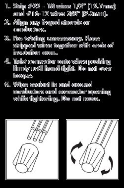
Small Wire Connector | LV9000) 1. Strip wires 13 mm.
IMPORTANT: Turn off power before installing or removing 2. Align frayed strands or conductors.
connector. Product to be used in accordance with local 3. Do not pre-twist. Place stripped wires with ends even,
and national codes. lead stranded wires slightly.
1. Strip wires ¾” and group bare wires ends together. Do 4. Twist connector onto wires pushing firmly until hand-
not pre-twist solid wire. tight. DO NOT over torque.
You must pre-twist stranded wire. If using both wire 5. Swipe excess sealant in and around conductors.
types, you must wrap stranded wire around untwisted 6. DO NOT REUSE.
solid wires (1a).
2. Insert wires through flexible sealing fingers and bend
bare wire ends together into either “V-Channel.” With
proper 3/4” strip length, wire tips just reach to edge of
round hole below “V” (2a).
Operating Modes
• Auto UD = Upper Digits
• Off LD = Lower Digits
• FC counter rest
• Manual FC
3. Separate connector, removing plastic “link” or “leg” from
inner sleeve. Push inner sleeve into Pre-filled outer
sleeve until double-locked. Pre-filled connection. Do not
reuse.
G75-DFC 22/04/21 Page 9 of 15
22/04/21 Page 8 of 15
DryConn #22 to #12 AWG- Wire Connectors (Provide by
DryConn). 22/04/21 Page 8 of 15
1. Strip #22 - #18 wires 1/2” (12.7mm)
And #16 - 12 wires 3/8” (9.5mm).
2. Align any frayed strands or conductors.
22/04/21 Page 8 of 15
3. Pre-twisting unnecessary. Place stripped wires together
with ends of insulation even.
4. Twist connector onto wires pushing firmly until hand-
22/04/21 Page 8 of 15
tight. Do not over torque.
5. Wipe sealant in and around conductors and connector
opening while tightening. Do not reuse.
8 A U T O M A T I O N & C O N T R O LIOM
BATTERY INSTALLATION
Before installing the battery
1. Read the safety instructions chapter of this document
2. Make sure that the solenoids and the DP wires are isolated from each other - prevent short circuits.
3. Using a Phillips screwdriver, remove the four battery cover screws (see the following drawing).
4. Remove the cover and the seal.
5. Install the 9V alkaline battery.
6. Reinstall the seal into its designated slot, put back the cover, and secure the four screws.
The LCD display shows:
• The actual differential pressure - DIF
• The pressure set point - SET
• The flushing cycles counter - FC
• While in flushing, a Faucet icon appeases on screen
• When the battery needs replacing, a Low Battery icon appears on screen
screws
Battery cover seal
When replacing the seal, push seal tabs
into slots.
Replacing the battery:
1. Replace the battery at the beginning of each irrigation season and whenever the Low Battery Symbol appears on the
controller’s screen.
2. Always use the best quality battery to ensure at least one year’s autonomous operation.
3. When replacing the seal, push its tabs into the slots.
Baccara landscape | solenoids 9G75-DFC Differential Filtration Controller The User Interface Monitoring the controller’s operation The G75-DFC has two operation modes: Auto and Off. The Auto mode The Auto mode is the running mode of the controller, while in this mode the upper digits (UD) of the screen display the current accumulation of the Flush Cycles Counter, and the lower digits (LD) display the Differential Pressure (DIF) and its Settings Value. When the controller backwashes the filters the Faucet Icon appears on the display’s upper line and the number of the currently backwashed filter blinks. When low battery state is detected the Battery Icon on the upper line of the screen starts blinking. The controller starts a backwash cycle (FC), when the current DIF reading is greater than the SET value for (n) number of consecutive DIF readings. The backwash cycle ends one minute after the last filter cleaning ends. The display turns OFF (blank) if no button is pressed for one minute. Pressing any button turns the display ON. The OFF mode This mode is used when the operation of the controller is paused, such as off season or when controlling the filters is not required. In the OFF mode the lower line of the controller (LD) displays OFF. In this mode the controller stops reading the DIF switch, and the display turns OFF (blank) if no button is pressed for one minute. Switching operation modes When the display is turned ON pressing the MODE button shortly (about 0.5 of a second) switches the controller from Auto to OFF mode and vice versa. The backwash cycles counter When the controller is in Auto mode, pressing the MODE button together with the (Plus) key displays the current value of the counter on the display’s upper line (UD). Resetting the counter to zero is done by pressing together the (Minus) key. The upper line displays c000 and the controller returns to Auto mode. Starting a backwash cycle manually When the controller is in Auto mode, pressing the SET button together with the (Plus) key starts a backwash cycle, the screen displays the Hand and the Faucet icons and the currently backwashing filter number blinks. The controller returns to Auto mode once the backwash cycle ends. To manually stop a backwash cycle press the SET button together with the (Minus) key. The cycle stops and the controller returns to Auto mode. 10 A U T O M A T I O N & C O N T R O L
IOM

Programing the controller
The G75-DFC controller has two types of operation parameters: factory-set parameters and user programable parameters.

Factory-Set Parameters:
The factory-set parameters cannot be changed by the user and they include the following:
• Pressure units: bar
• Flush Cycle (FC) delay: 2 consecutive readings of DIF≥SET before the FC starts.
• Sample Interval time: In Auto operation mode, as the Differential Pressure (DIF) readings get closer to the SET point,
   the interval time between samples shortens. The maximal interval time between readings is 60 seconds while the
   minimal interval time between readings is 5 seconds.
• The delay between filters during flushing (Off time between valves) is 20 seconds.
• Number of consecutive flush cycles (FC) for alarm is 5 cycles.
• Sensor calibration - cannot be changed by the user.

User Programable Parameters:
Setting the backwash time (Valve ON Time):
The default value of this parameter is 40 seconds per filter, while the programable range is up to 5 minutes and 59
seconds.
1. Press the MODE button until the following screen appears:

2.   Using the    and the    keys, adjust the seconds.
3.   Press SET to continue.
4.   Using the    and the    keys, adjust the minutes.
5.   Press SET to complete the setting.

                                                                                                 Baccara landscape | solenoids   11
G75-DFC Differential Filtration Controller
Setting the Interval Time between backwash cycles:
Setting
Setting
This parameter the
the Interval Interval
is the
Time between Time
maximal time between
backwash
between
cycles: backwash cycles
two consecutive backwash cycles if no backwash cycle is triggered by the
Thisparameter
parameter
differential
This is the
pressure
is theswitch
maximal
maximal time
timebetween
(DIF). betweentwo
twoconsecutive
consecutivebackwash
backwash cycles
cycles if no backwash
if no backwash cycle is triggered
cycle by by
is triggered thethe
differential pressure switch (DIF).
differential pressure switch (DIF).
The
The programable
programable rangerangeisisupuptoto2323 hours
hours andand 59 minutes,
59 minutes, identified
identified by “A”. by
if “A”“A”. if “A” isthe
is selected, selected, the Interval
Interval Time Time
parameter
parameter
is ignored.
The is ignored.
programable range is up to 23 hours and 59 minutes, identified by “A”. if “A” is selected, the Interval Time
parameter is ignored.
The factory-set parameters cannot be changed by the user and they include the following:
1. Long press the MODE button followed by a short press on the MODE button: the following screen appears:
1. Long press the MODE button followed by a short press on the MODE button: the following screen appears:
1. Long press the MODE button followed by a short press on the MODE button: the following screen appears:
2. Using the and the keys, adjust the minutes. If “A” is selected, press SET to complete the setting.
2. 2.
Using
3. the SET
Press
Using theand the
and thekeys, adjust
to continue. the minutes.
keys, adjust If “A” is selected,
the minutes. press SETpress
If “A” is selected, to complete the setting.
SET to complete the setting.
3. 3.
Press
4. SET
Using to
thecontinue.
and the
Press SET to continue. keys, adjust the hours.
4. 4.
Using
5. Press
Using theand
the SET the
and thekeys,
to complete theadjust the hours.
setting.
keys, adjust the hours.
5. 5.
Press SET SET
Press to complete the setting.
to complete the setting.
Setting the number of filters:
Setting
Setting
The the
the number
parameter number
of filters: of filters:
designates the operating filters in the system (up to three filters); the default value is #1.
Theparameter
The parameter designates
designates the
the operating
operating filters
filtersininthe
thesystem
system(up
(uptotothree
threefilters); thethe
filters); default value
default is #1.
value is #1.
Note: if needed (for technical reasons) the user may set the designated number not in a consecutive order.
Note: if needed (for technical reasons) the user may set the designated number not in a consecutive order.
Note: if needed (for technical reasons) the user may set the designated number not in a consecutive order.
1. 1.
LongLong the MODE
presspress the MODE
button button
followedfollowed
by two short presses
by two the MODE
onpresses
short the MODE
onbutton: the following
button:screen appears: screen
the following
appears:
1. Long press the MODE button followed by two short presses on the MODE button: the following screen
appears:
2. 2.
UsingUsing
the thekey to key tovalve
select select#1,valve
valve#1, valve #1ONremans
#1 remans ON#2
and valve and valve
starts #2 starts
blinking. Use blinking.
the Use
key the
to deselect akey to
valve.
2. deselect
Using thea valve.key to select valve #1, valve #1 remans ON and valve #2 starts blinking. Use the key to
3. Repeat the above
deselect process for filters number 2 and 3.
a valve.
3. Repeat the above process for filters number 2 and 3.
3. Repeat the above process for filters number 2 and 3.
G75-DFC 22/04/21 Page 13 of 15
G75-DFC 22/04/21 Page 13 of 15
12 A U T O M A T I O N & C O N T R O LIOM
TROUBLESHOOTING
Problem Cause Check Solution
The controller does 1. No water 1. Check the inlet pressure 1. Make sure that the water
not perform flushing and the system flowrate supply (or the pump) is on.
(Automatic or Manual) 2. Empty Battery 2. Check the battery 2. Replace the battery
3. Incorrect DP settings - 3. Check the DP across the 3. Lower the DP setting to
High filtration system. appropriate valve for the
If it is lower than the specific water quality and
setting, make sure it is dirt load.
increasing over time.
If not check the filters
integrity.
4. No control pressure 4. Check the control tubes 4. Clean the control tubes
filter for clogging filter
The controller backwashes 1. Incorrect DP settings - Low 1. Check if the DP is set too 1. Set the DP to 0.5 bar
constantly low
2. Sensor not zeroed 2. Disconnect the upstream 2. Disconnect the upstream
and downstream tubes and downstream tubes
and check that the and perform ‘Zero offset’
pressure indicated in the from the advanced
octopus app is 0 settings screen
Valve does not 1. The valve number selected 1. Check the valve number 1. Select the correct valve
open / close is incorrect number
2. Faulty solenoid 2. Check the solenoid 2. Replace the solenoid
3. No control pressure 3. Check the control tubes’ 3. Clean the control tubs’
filter for clogging filter
4. Faulty flushing valve 4. Check the valve 4. Service or replace the
valve
Valves open instead of 1. Solenoid valves in reverse 2. check if the solenoids 3. Reverse the solenoids
closing and close instead polarity are connected in reverse connections polarity
of opening polarity
Baccara landscape | solenoids 13G75-DFC Differential Filtration Controller
WARRANTY
Warranty:
BaccaraGeva
Baccara Geva ACS Ltd. Ltd. (“Baccara”)
("Baccara")products
products arearemade madeto exacting
to exacting standards of design,
standards material,
of design, workmanship,
material, and quality
workmanship, and
control and are warranted to be free of defects in material and workmanship and reasonably
quality control and are warranted to be free of defects in material and workmanship and reasonably fit for the uses set fit for the uses set forth in
Baccara’s catalog or the purchase order specifications for twelve (12) months from delivery or eighteen (18) months from
forth in Baccara’s catalog or the purchase order specifications for twelve (12) months from delivery or eighteen (18)
shipment of the product to buyer, whichever occurs first, if properly installed and maintained and under the normal use
months fromfor
and service shipment
which the of product
the product to buyer, whichever occurs first, if properly installed and maintained and under
is intended.
the normal use and service for which the product is intended.
This warranty does not apply in cases of damage resulting from breakage, negligence, neglect (such as neglect in the
maintenance
This warranty of the not
does product,
applyincluding
in cases the use of unfiltered
of damage resultingwater,
from ifbreakage,
applicable), abuse, mishandling,
negligence, neglect (suchnormal
as depreciation
neglect in the
or wear and tear, short circuit, breakdown resulting from an irregular power supply (voltage drop), fall or any accident
maintenance of the product, including the use of unfiltered water, if applicable), abuse, mishandling, normal
including natural disaster and force major damage. For clarity, any repair of such damage, if possible, shall involve a fee.
depreciation or wear and tear, short circuit, breakdown resulting from an irregular power supply (voltage drop), fall or
This warranty will not apply in the event of a breakdown due to operation not in accordance with the instructions for use
any accidentinincluding
mentioned our catalog natural
and the disaster
customer and information
force majeure damage. For clarity, any repair of such damage, if possible,
leaflets.
shall
Buyerinvolve a fee. the product within ten days of delivery and must immediately notify Baccara of any defects. Failure to
shall inspect
so notify
This Baccara
warranty will within suchinten-day
not apply the event period
of ashall constitute
breakdown duea waiver of all claims
to operation not inbyaccordance
Buyer against withBaccara arising out for
the instructions
of such defects.
use mentioned in our catalog and the customer information leaflets.
This warranty is in lieu of all other warranties whether they are statutory, express or implied, including, among other
things,shall
Buyer any inspect
implied thewarranty
product of merchantability
within ten daysfitness for a particular
of delivery and must purpose
immediatelynot set forthBaccara
notify in Baccara’s catalog.
of any defects. Failure
toThe
so warranty will expire
notify Baccara in the
within such event of any
ten-day modification
period and / or repair
shall constitute made
a waiver of to
allthe product
claims not byagainst
by Buyer a person authorized
Baccara arising
by Baccara and
out of such defects. / or the use of chemicals not in accordance with our instructions.
Baccara shall not be liable for any consequential, incidental, or special damages resulting directly or indirectly from the
This warranty
design, is in
material, lieu of all other
workmanship, warranties
operation whetherofthey
or installation any of areitsstatutory,
products andexpress or implied,
neither assumes including, among
nor authorizes anyother
other person
things, to assume
any implied on itsofbehalf
warranty any other liability
merchantability fitnessinforconnection
a particular therewith.
purposeBuyer’s
not setexclusive remedy shall
forth in Baccara’s be the
catalog.
repair or replacement, according to Baccara’s exclusive discretion, of any such defective product, after inspection and
The warranty
verification by will expire
Baccara, in the that
provided event suchof defective
any modification
product was andpurchased
/ or repairfrommade to the
Baccara product
or from any ofnot by a person
its authorized
authorized by Baccara and / or the use of chemicals not in accordance with our instructions.
distributors. Service and repair pursuant to this warranty shall be provided in Baccara’s facilities and is subject to
presenting the warranty certificate, invoice and delivery of the product for inspection. Buyer shall deliver the product to
Baccara shall not facilities
one of Baccara’s be liableandfor collect
any consequential,
it from the same incidental, or special
facility once repairdamages resulting directly or indirectly from the
is completed.
design, material, workmanship, operation or installation of any of its products and neither assumes nor authorizes any
other person to assume on its behalf any other liability in connection therewith. Buyer’s exclusive remedy shall be the
repair or replacement, according to Baccara's exclusive discretion, of any such defective product, after inspection and
verification by Baccara, provided that such defective product was purchased from Baccara or from any of its authorized
distributors. Service and repair pursuant to this warranty shall be provided in Baccara's facilities and is subject to
presenting the warranty certificate, invoice and delivery of the product for inspection. Buyer shall deliver the product
to one of Baccara's facilities and collect it from the same facility once repair is completed.
G75-DFC 22/04/21 Page 15 of 15
14 A U T O M A T I O N & C O N T R O LIOM G75-DFC - Differential Filtration Controller | IOM 15
BACCARA WORLD WIDE
BACCARA Corporate Headquarters            Baccara Australia Pty Ltd.            BACCARA España
Kvutzat Geva, 1891500, Israel             15/347 Bay Rd. Cheltenham | VIC,      C/ Marqués de Monteagudo N° 24, Madrid
T. +972 4 6535960                         Australia 3192                        T. (+34) 913446310
F. +972 4 6531445                         T. +61 (0) 3 9553 4963                spain@baccara-geva.com
info@baccara-geva.com                     F. +61 (0) 3 9553 4965                https://www.linkedin.com/company/baccara-espana/
www.baccara-geva.com                      Cheltenham, Victoria 3192 Australia
                                          australia@baccara-geva.com
                                          www.baccarageva.com.au
                                          Store: www.baccarastore.com.au

                                          Baccara USA                           Baccara India
                                          1312 W Stanford Ave                   Empirical Business Center,
                                          Englewood, CO 80110                   Office no. 405, Navale Icon, Near
                                          T. 719-304-4224                       Navale Bridge, Off NH4, Narhe,
                                          F. 520 746 9390                       Pune. PIN- 411041. [Maharashtra]
                                          info.us@baccara-geva.com              T. +91 90 499 94197
                                          www.baccarausa.com                    vishal@baccara-geva.com
                                                                                                                                    08/2021

                                                                                                                 Tackling climate
A U T O M A T I O N   &   C O N T R O L                                                                          change together
You can also read