Intraoperative hyperspectral label-free imaging: from system design to first-in-patient translation - UCL Discovery
←
→
Page content transcription
If your browser does not render page correctly, please read the page content below
Journal of Physics D: Applied Physics

PAPER • OPEN ACCESS

Intraoperative hyperspectral label-free imaging: from system design to
first-in-patient translation
To cite this article: Michael Ebner et al 2021 J. Phys. D: Appl. Phys. 54 294003

View the article online for updates and enhancements.

                              This content was downloaded from IP address 193.60.240.99 on 26/05/2021 at 11:29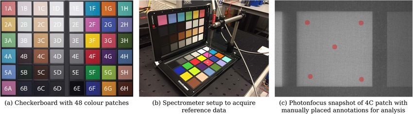
Journal of Physics D: Applied Physics
J. Phys. D: Appl. Phys. 54 (2021) 294003 (16pp) https://doi.org/10.1088/1361-6463/abfbf6
Intraoperative hyperspectral label-free
imaging: from system design to
first-in-patient translation
Michael Ebner1,10, Eli Nabavi1,10, Jonathan Shapey1,2,3,10, Yijing Xie1,
Florentin Liebmann4,5, José Miguel Spirig6, Armando Hoch6, Mazda Farshad6,
Shakeel R Saeed3,7,8, Robert Bradford3, Iain Yardley9, Sébastien Ourselin1,
A David Edwards1,9, Philipp Führnstahl4 and Tom Vercauteren1,∗
1
School of Biomedical Engineering & Imaging Sciences, King’s College London, London, United
Kingdom
2
Wellcome / EPSRC Centre for Interventional and Surgical Sciences, UCL, London, United Kingdom
3
Department of Neurosurgery, National Hospital for Neurology and Neurosurgery, Queen Square,
London, United Kingdom
4
Research in Orthopedic Computer Science (ROCS), Balgrist University Hospital, University of Zurich,
Balgrist CAMPUS, Zurich, Switzerland
5
Laboratory for Orthopaedic Biomechanics, ETH Zurich, Zurich, Switzerland
6
Department of Orthopaedics, Balgrist University Hospital, University of Zurich, Zurich, Switzerland
7
The Ear Institute, UCL, London, United Kingdom
8
The Royal National Throat, Nose and Ear Hospital, London, United Kingdom
9
Department of Paediatric Surgery, Evelina London Children’s Hospital, London, United Kingdom
E-mail: tom.vercauteren@kcl.ac.uk
Received 29 December 2020, revised 30 March 2021
Accepted for publication 27 April 2021
Published 14 May 2021
Abstract
Despite advances in intraoperative surgical imaging, reliable discrimination of critical tissue
during surgery remains challenging. As a result, decisions with potentially life-changing
consequences for patients are still based on the surgeon’s subjective visual assessment.
Hyperspectral imaging (HSI) provides a promising solution for objective intraoperative tissue
characterisation, with the advantages of being non-contact, non-ionising and non-invasive.
However, while its potential to aid surgical decision-making has been investigated for a range of
applications, to date no real-time intraoperative HSI (iHSI) system has been presented that
follows critical design considerations to ensure a satisfactory integration into the surgical
workflow. By establishing functional and technical requirements of an intraoperative system for
surgery, we present an iHSI system design that allows for real-time wide-field HSI and
responsive surgical guidance in a highly constrained operating theatre. Two systems exploiting
state-of-the-art industrial HSI cameras, respectively using linescan and snapshot imaging
technology, were designed and investigated by performing assessments against established
10
Authors contributed equally.
∗
Author to whom any correspondence should be addressed.
Original Content from this work may be used under the
terms of the Creative Commons Attribution 4.0 licence. Any
further distribution of this work must maintain attribution to the author(s) and
the title of the work, journal citation and DOI.
1361-6463/21/294003+16$33.00 1 © 2021 The Author(s). Published by IOP Publishing Ltd Printed in the UK
J. Phys. D: Appl. Phys. 54 (2021) 294003                                                                                                    M Ebner et al

design criteria and ex vivo tissue experiments. Finally, we report the use of our real-time iHSI
system in a clinical feasibility case study as part of a spinal fusion surgery. Our results
demonstrate seamless integration into existing surgical workflows.
Keywords: hyperspectral imaging, hyperspectral imaging, medical device, translational research,
computer assisted interventions, exoscope, first-in-patient
(Some figures may appear in colour only in the online journal)

1. Introduction                                                                        et al 2019, Fabelo et al 2018) tissue information that are par-
                                                                                       ticularly interesting for surgical decision making. However,
Many difficult intraoperative decisions with potentially life-                         whilst HSI has been investigated for the assessment of various
changing consequences for the patient are still based on the                           clinical conditions such as peripheral vascular disease (Chi-
surgeon’s subjective visual assessment. This is partly because,                        ang et al 2017), retinal eye disease (Desjardins et al 2016),
even with the most advanced current surgical techniques, it                            hemorrhagic shock (Cancio et al 2006), healing in foot ulcers
may still not be possible to reliably identify critical structures                     of diabetic patients (Khaodhiar et al 2007) and cancer detec-
during surgery. Neuro-oncology and orthopaedic surgery are                             tion (Fei et al 2017), its in vivo surgical use has been restric-
among the specialties that benefited most from advanced visu-                          ted to a few clinical research cases only (Shapey et al 2019).
alisation techniques and computer-assisted technologies. Nav-                          For example, while the HELICoiD research system (Fabelo
igation solutions have for example been presented for brain                            et al 2018) demonstrated promising clinical research results
(Gerard et al 2017) and spinal (Helm et al 2015) procedures                            for in vivo brain tumour detection (Fabelo et al 2019), its size
to map preoperative information such as magnetic resonance                             is prohibitive for clinical adoption during surgery. Other sys-
imaging (MRI) or computed tomography (CT) to the anatomy                               tems presented for the intraoperative assessment of tissue per-
of the patient on the surgical table. However, navigation based                        fusion and oxygenation—including breast (Gioux et al 2011),
on preoperative imaging cannot reliably account for intra-                             oral cancer (Klaessens et al 2013), renal (Best et al 2013),
operative changes creating uncertainty for surgical decision                           epilepsy (Noordmans et al 2013), neurovascular (Mori et al
making. Interventional imaging and sensing, such as surgical                           2014) and gastrointestinal surgery (Yoon et al 2019, Barberio
microscopy, fluorescence imaging, point-based Raman spec-                              et al 2020)—further demonstrate the potential of iHSI. Yet,
troscopy, ultrasound and intra-operative MRI, may be used                              these are prone to produce motion artefacts due to insuf-
by the surgeon either independently or as adjunct to navig-                            ficient imaging speed for a dynamic scene during surgery.
ation information to visualise the operated tissues. However,                          More recently, two intraoperative systems based on pushb-
tissue differentiation based on existing intraoperative imaging                        room HSI cameras were presented that allow for integration
remains challenging because of stringent operative constraints                         into the surgical workflow: In Mühle et al (2021), the TIV-
in the clinical environment (e.g. intraoperative MRI or CT), or                        ITA system (Kulcke et al 2018) was attached to a surgical
imprecise tumour delineation (e.g. ultrasound).                                        microscope to capture in vivo neurosurgery data; in Köhler
    Advanced optical imaging techniques provide a prom-                                et al (2020), a laparoscopic HSI camera was presented and
ising solution for intraoperative tissue characterisation, with                        tested using resected esophagus tissue and in Hu et al (2020)
the advantages of being non-contact, non-ionising and non-                             a HSI imaging system was tested during liver cancer surgery.
invasive. By splitting light into multiple narrow spectral bands                       While these systems show potential for seamless integration
far beyond what the naked eye can see, hyperspectral ima-                              into the surgical workflow, their restricted imaging speed is
ging11 (HSI) carries diagnostic information about tissue prop-                         likely to remain an inhibitor for adoption during surgery. For
erties that can be used for objective tissue characterisation                          increased real-time imaging speed, recently developed snap-
without the need of any exogenous contrast agent.                                      shot HSI camera systems have been used to assess brain per-
    As a label-free imaging modality, HSI and its diagnostic                           fusion in neurosurgery (Pichette et al 2016) and to perform
capabilities have been explored for biomedical imaging                                 preclinical skin perfusion analysis (Ewerlöf et al 2017). How-
applications over many years (Lu and Fei 2014, Hu et al                                ever, while snapshot HSI sensors permit real-time HSI cap-
2017, Halicek et al 2019, Shapey et al 2019, Clancy et al                              ture with video-rate imaging, spatial resolution is limited and
2020) In particular, it has been demonstrated that the spectral                        needs to be accounted for in a post-processing step called
signature of tissues captured by HSI can provide both quant-                           demosaicking (Dijkstra et al 2019, Tsagkatakis et al 2019).
itative functional (e.g. blood perfusion and oxygenation sat-                          Moreover, previously presented snapshot iHSI works did not
uration levels) (Klaessens et al 2013, Mori et al 2014) and                            methodologically map out and address the critical design con-
semantic (e.g. tissue type such as tumour vs healthy) (Kho                             siderations to ensure a seamless integration into the surgical
                                                                                       workflow.
                                                                                           While various HSI systems have been tested in a surgical
11 Depending on the number of acquired bands, hyperspectral imaging may                environment to investigate the potential of iHSI, to the best of
also be called multispectral imaging. We will continue to refer to hyperspectral       our knowledge, no HSI system has been presented allowing for
imaging regardless of the number of bands used for simplicity.                         strict clinical requirements including a means of maintaining

                                                                                   2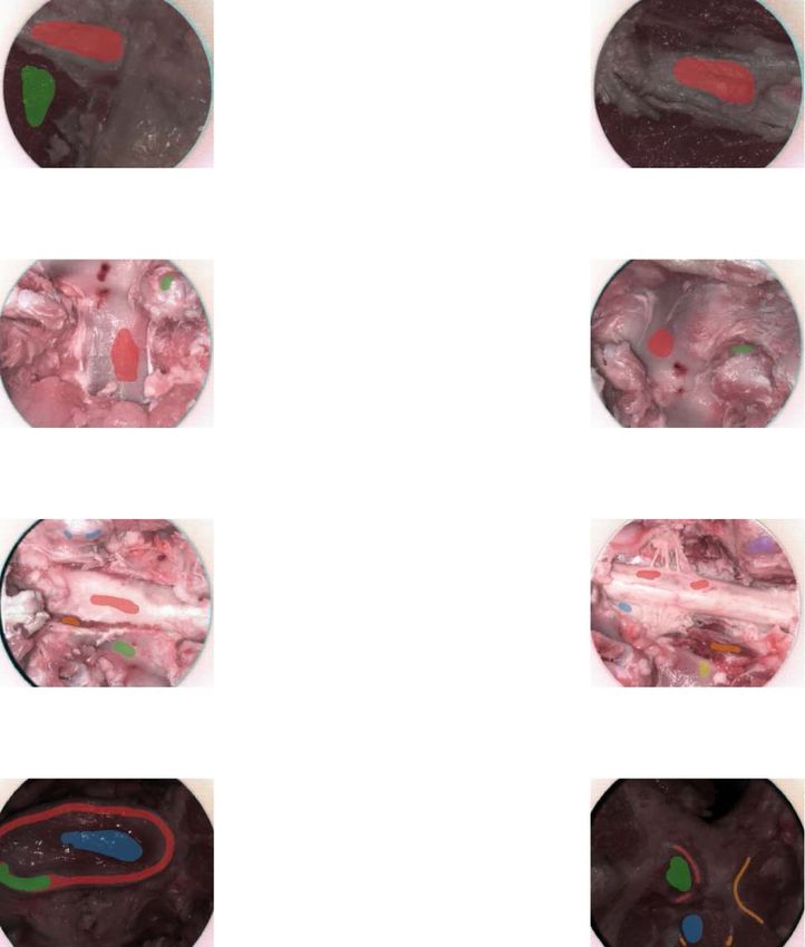
J. Phys. D: Appl. Phys. 54 (2021) 294003                                                                                          M Ebner et al

Figure 1. Schematic diagram of our intraoperative hyperspectral imaging (HSI) system illustrated for the example of spine surgery. A
snapshot HSI camera system was used for the in-patient clinical feasibility case study as part of a spinal fusion surgery. Video-rate HSI data
was acquired during surgery. An example in vivo snapshot hyperspectral mosaic image demonstrating the exposed dura of the spinal cord
following laminectomy is provided.

sterility and ensuring seamless integration into the surgical             2.1. Intraoperative HSI system design requirements
workflow that can provide real-time information for intraop-
                                                                          Our main design assumption is that the intraoperative applic-
erative surgical guidance.
                                                                          ation of an HSI camera system is facilitated by developing
   In this paper, our contributions are four-fold: (a) by building
                                                                          a standalone light-weight device independent of an operat-
on our preliminary work (Shapey et al 2018), we first present a
                                                                          ing microscope typically used for neurosurgery. In particu-
set of design requirements, including functional and technical
                                                                          lar, by ensuring compatibility with surgical telescopes, such
requirements, critical for an iHSI system to provide real-time
                                                                          as an exoscope (Ricciardi et al 2019) or endoscope, a mod-
wide-field HSI information for seamless surgical guidance in
                                                                          ular and flexible system design can be achieved suitable for
a highly constrained operating room (OR); (b) we present
                                                                          both open or endoscopic surgery across surgical specialities.
and evaluate our developed iHSI system against these require-
                                                                          Following this assumption, tables 1 and 2 provide an over-
ments by considering two state-of-the-art industrial HSI cam-
                                                                          view of design requirements considered for a hyperspectral
era systems based on linescan and snapshot imaging techno-
                                                                          imaging system for intraoperative surgical guidance includ-
logy as further described in section 3.1; (c) we perform ex vivo
                                                                          ing minimum and target requirements. These are divided into
animal tissue experiments in a controlled environment with
                                                                          (a) functional requirements, i.e. requirements imposed by the
our proposed iHSI setup to investigate tissue properties using
                                                                          clinical environment in the OR during surgery (table 1), and
both camera systems; and (d) we report the use of our real-
                                                                          (b) technical requirements, i.e specifications for a HSI system
time iHSI system (figure 1) during an ethically-approved in-
                                                                          to achieve high-fidelity imaging data to satisfy the listed
patient clinical feasibility case study as part of a spinal fusion
                                                                          functional requirements for the purpose of real-time surgical
surgery therefore successfully validating our assumptions that
                                                                          guidance (table 2). When objective requirements cannot be
this system can be seamlessly integrated into the OR without
                                                                          provided, best estimates are given based on our experience as
interrupting the surgical workflow.
                                                                          outlined below.
                                                                              As part of surgical requirements, sterility of the iHSI sys-
                                                                          tem must be ensured so that safe handling by the surgical
2. Intraoperative HSI system for real-time surgical                       team is possible (F1), it must adhere to standard technical
guidance                                                                  safety specifications (F2), light and illumination requirements
                                                                          must not impede surgical workflow (F3), and the device must
In this section, we present the key design requirements of an             be easy to maintain and clean in compliance with standard
HSI for intraoperative surgical guidance suitable for open sur-           surgical practice (F4). It should be securely mounted dur-
gery. By following these criteria, the iHSI system illustrated            ing the procedure but the handheld device should be eas-
in figure 1 is introduced and described.                                  ily manoeuvrable, allowing for controlled mobilisation and

                                                                      3
J. Phys. D: Appl. Phys. 54 (2021) 294003                                                                                          M Ebner et al

Table 1. Overview of functional design requirements of a hyperspectral imaging system for intraoperative surgical guidance. Corresponding
technical requirements from table 2 are listed in the rightmost column.
                       Minimum Requirement                            Target Requirement                           Req

F1 Surgical safety     Safe and sterile intraoperative use must       Ibid.                                        T1,T2,T8,T9,T12
and sterility          be possible throughout the surgical
                       procedure.
F2 Technical           Device must comply with electrical and         Ibid.                                        T1,T2,T4–T6,T8,T9,T16,
safety                 light source safety standards so that it may
                       be used safely within the operating theatre
                       without causing tissue injury.
F3 Lighting            Light and illumination requirements must       Ibid. Additionally, light and illumination can T7,T10,T18
                       not impede surgical workflow.                  be adjusted to accommodate the surgeon’s
                                                                      needs.
F4 Maintenance         Maintenance and cleaning requirements          Ibid.                                          T1,T2
                       must comply with standard clinical
                       practice.
F5 Device              Device must be securely held or mounted    Handheld device must be easily                   T2–T6,T10,T12
handling               during the procedure but easily            manoeuvrable and be light enough to
                       manoeuvrable.                              position securely without the need for an
                                                                  assistant.
F6 Anatomical          Field of view (FOV) and depth of imaging Ibid. Additional monitoring capabilities are       T11–T13,T19
coverage               must provide information compatible with available.
                       the surgical action.
F7 Anatomical          Critical functional or semantic features   Multiple functional and semantic features to     T7,T11 and T13–T19
feature                to increase surgical precision and patient increase surgical precision and patient safety
                       safety during the procedure.               for comprehensive patient monitoring.
F8 Anatomical          Resolution suitable to spatially           Resolution suitable to spatially                 T11 and T13–T17
detail                 identify/differentiate tissue within the   identify/differentiate anatomical tissue with
                       surgical field.                            high anatomical detail.
F9 Imaging rate        Video-rate imaging for instant surgeon     Fast video-rate imaging for instant and          T19
                       feedback and seamless workflow             smooth surgeon feedback and seamless
                       integration.                               workflow integration.
F10 Visualisation      Accurate visualisation of extracted        Intuitive and accurate visualisation of          T7 and T15–T18
                       information for surgical guidance.         extracted information for seamless surgical
                                                                  guidance.

immobilisation of the imaging system by a single operator                     better user experience can be achieved using intuitive display
without the need for an assistant (F5). The spatial resolution                systems F10.
and spectral information captured within the surgical image                       To ensure surgical safety and sterility, system maintenance
must be compatible with the surgical action (F6), i.e. the pro-               should be straightforward and it should be possible to clean
vision of wide-field information covering the minimal region                  the system’s components effectively using a standard anti-
that provides sufficient context for surgical decision making.                microbial surface wipe (T1). The minimum requirements of
In addition, it should facilitate the ability of broader tissue               HSI camera dimensions and weight are based on the estimates
surveillance relevant to the surgery. The device must be cap-                 in Shapey et al (2018) obtained through a prototyping-testing
able of providing critical functional or semantic tissue inform-              design thinking methodology (Yock et al 2015), i.e. a cam-
ation and should be capable of providing detailed informa-                    era smaller than 10 × 10 × 12 cm3 (T2) and lighter than 1.0
tion on multiple features for comprehensive patient monitor-                  kg (T3). For a system with dimensions smaller than 6 × 6 × 8
ing in order to increase surgical precision and patient safety                cm3 standard drapes for covering the camera can be used
during the procedure (F7). In the case of neuro-oncology sur-                 to ensure sterility. Additionally, all camera edges must be
gery, this might be the demarcation of tissue boundaries to                   smooth to prevent tearing of sterile drapes and injuring of
clearly demonstrate tumour tissue and its relation to critical                staff members (T4). A maximum camera temperature of 40
                                                                              ◦
brain structures such as nerves, blood vessels or normal brain.                 C ensures technical safety for device handling in addition to
Furthermore, image resolution must be sufficiently detailed                   reduced dark currents for maintaining appropriate signal-to-
to facilitate spatial differentiation between tissue types within             noise ratios (SNRs) during image acquisition (T5). The num-
the surgical field of view F8). Imaging must be displayed at                  ber of cables for powering of and data connection with the
video-rate to facilitate instant surgeon feedback and seamless                camera must be kept at a minimum (T6). To enable adequate
workflow integration with higher video-rates allowing for a                   iHSI, a suitable light source must be available to provide suf-
smoother experience (F9). Accurate visualisation of extrac-                   ficient energy across the active spectral range of the HSI cam-
ted information is essential for surgical guidance whereby a                  era (T7), but technical safety and light safety considerations

                                                                          4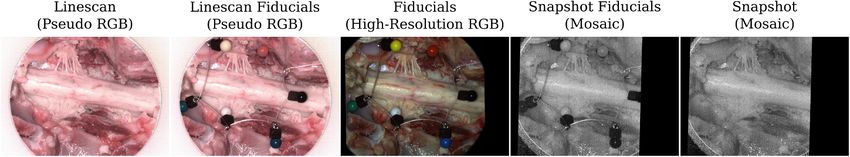
J. Phys. D: Appl. Phys. 54 (2021) 294003                                                                                           M Ebner et al

Table 2. Overview of technical requirements of a hyperspectral imaging system for intraoperative surgical guidance. Corresponding
functional requirements from table 1 are listed in the rightmost column.
                      Minimum Requirement                           Target Requirement                              Req

T1 System             System components may be effectively          Ibid. Additional camera housing resistance      F1,F2,F4
maintenance           cleaned using a universal antimicrobial       protects against dust and splashing liquids.
                      surface wipe.
T2 Camera             Smaller than 10 × 10 × 12 cm3 .               Smaller than 6 × 6 × 8 cm3 .                    F1,F2,F4,F5
dimensions
T3 Camera weight      Lighter than 1 kg.                            Lighter than 0.5 kg.                            F5
T4 Camera             No sharp edges on camera housing.             Ibid.                                           F2,F5
housing
T5 Camera             Temperature lower than 40 ◦ C.                Ibid.                                           F2,F5
temperature
T6 Camera             No more than two cables to provide power      One cable to provide both power and fast data F2,F5
connectivity          and fast data link                            connection.
T7 Light source       Adequate uniform coverage of required         Ibid.                                         F2,F3,F7,F10
energy                spectral range (cf T16).
T8 Light source       Adherence to MPE limits with ionizing UV      Ibid.                                           F1,F2,F7,F10
safety                wavelengths (< 400 nm) eliminated.
T9 System mount       Static system mount possible.                 Adjustable system mount possible.               F1,F2
T10 Camera            Manual adjustments of camera acquisition      Automatic adjustments to obtain ideal camera    F5,F6
settings              settings.                                     acquisition settings.
T11 Focus             Manual focus of target tissue.                Autofocus of target tissue.                     F6–F8
T12 Working           Fixed WD between 200 mm and 300 mm.           Variable WD between 200 mm and 750 mm.          F1,F3 and F5–F6
distance
T13 Field of View     Fixed FOV between 40 mm and 60 mm.            Variable FOV between 40 mm and 150 mm.          F6–F8
T14 Depth of          At least 20 mm DOF for 50 mm FOV at           Variable 15 mm to 100 mm DOF.                   F6–F8
Field                 fixed WD of 250 mm.
T15 Spectral          At least 16 spectral bands.                   At least 100 spectral bands for fine spectral   F2,F7,F8,F10
bands                                                               sampling.
T16 Spectral range    At least a spectral coverage of 160 nm.       At least a spectral coverage of 500 nm.         F2,F7,F8,F10 and T7
T17 Spatial image     1920 × 1080 pixels.                           3840 × 2160 pixels.                             F6–F8,F10
definition
T18 Image             Satisfactory image calibration to enable      Seamless and on-the-fly calibration possible    F3,F7,F10
calibration           reliable feature extraction during surgery.   for reliable feature extraction depending on
                                                                    surgical requirements and light conditions.
T19 Imaging rate      Video-rate imaging of at least seven FPS.     Video-rate imaging of at least 30 FPS.          F6,F7,F9

must be adhered to so that no injury is caused to the patient               require re-focusing which can either be achieved using manual
due to light exposure (T8). This includes adhering to the max-              or autofocus arrangements (T11). A fixed working distance
imal permissible exposure (MPE) with ionizing ultraviolet                   (WD) between 200 and 300 mm (T12) with a fixed field of
(UV) wavelengths below 400 nm (Yun and Kwok 2017).                          view (FOV) between 40 mm and 60 mm (T13) and a depth of
Light source setting adjustments must be possible to ensure                 field (DOF) of at least 20 mm (T14) are the minimum require-
optimal illuminant conditions for acquiring HSI information                 ments necessary for iHSI (Nishiyama 2017) but the ideal scen-
during surgery (F3,T10). Besides optimal light intensity set-               ario includes a system capable of variable WDs, FOVs and
tings depending on the surgical scene, this may include adjust-             DOFs in order to maximise compatibility with current sur-
ment of optical filters to acquire high-fidelity HSI signal meas-           gical visualisation systems (Langer et al 2020). The number
urements depending on the imaging requirements of the HSI                   of spectral bands, spectral range and spatial image definition
camera. Ideally, these settings are adjusted by automatically               largely depend on the clinical application to provide the critical
accounting for dynamic changes in the OR such as illumina-                  functional and/or semantic features. Our assumption based on
tion. A static mounting system is the minimum requirement to                reviewing the previous literature and our own experience is
ensure adequate intraoperative device handling (T9). Camera                 that tens of well-defined spectral bands are required to achieve
settings will need to be adjusted depending on the surgical con-            significant improvement with respect to standard RGB ima-
text to acquire high-fidelity HSI information (T10). By meet-               ging. Based on the availability of industrial state-of-the-art
ing the target requirements for camera dimension and weight                 snapshot HSI sensors (cf table 3), we specified that the min-
(T2,T3), further improvements in device handling may be                     imum requirements for an iHSI system during surgery are 16
achieved. High-fidelity tissue information requires the respect-            spectral bands (T15) and a spectral range of at least 160 nm
ive target tissue to be within the imaging field of view and                (T16). Similarly, the use of at least 100 spectral bands with
kept in focus during HSI acquisition. During surgery this may               at least 500 nm spectral coverage is technically feasible (cf

                                                                       5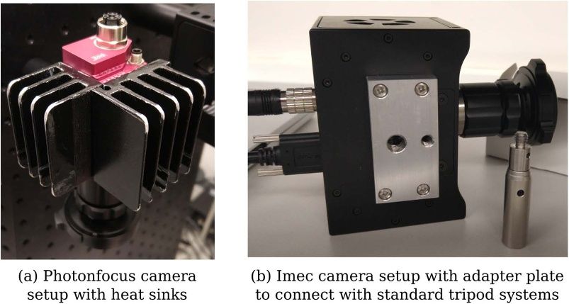
J. Phys. D: Appl. Phys. 54 (2021) 294003                                                                                               M Ebner et al

Table 3. Verification of intraoperative hyperspectral imaging systems based on whether requirements as outlined in table 2 are met.
Assessment is performed for two camera setups with ratings (R) of 0 (minimum requirement not met), 1 (minimum requirement met) and 2
(target requirement met) using our current system designs.
                             Linescan camera based                                  R    Snapshot camera based                               R

T1 Camera maintenance All components may be effectively cleaned using                1   Ibid.                                               1
                      a universal surface wipe.
T2 Camera Dimensions 10 × 7 × 6.5 cm3 .                                              1   6 × 6 × 5.4 cm3 (incl. heat sinks).                 2
T3 Camera Weight      0.58 kg.                                                       1   0.28 kg (incl. heat sinks).                         2
T4 Camera housing     Camera housing with smooth edges.                              2   Ibid. Additionally provided heat sinks with         2
                                                                                         rounded edges.
T5 Camera temperature Active cooling system ensures low camera                       2   Passive cooling system (heat sinks) ensures low     2
                       temperatures.                                                     camera temperatures.
T6 Camera connectivity Two cables.                                                   1   Single cable (GigE connection).                     2
T7 Light Source Energy Xenon light source ensures sufficient                         2   Ibid.                                               2
                       illumination across VIS & NIR spectral ranges
                       (250–1050 nm).
T8 Light Source Safety 470–900 nm (VIS & NIR).                                       2   665–975 nm (NIR).                                   1
T9 System mount        Not compatible with currently-available surgical              0   Compatible with standard sterile mechanical arm     2
                       supports.                                                         systems.
T10 Camera Settings    Adjustments possible using software control.                  2   Ibid.                                               2
T11 Focus              Optical system allows for manual focus for                    1   Ibid.                                               1
                       specific focal distance.
T12 Working distance
                       System design using scope and adjustable lenses               2   Ibid.                                               2
(WD)
                       allows imaging distances between 250–750 mm.
T13 Field of View      Optical system allows for 50 mm FOV at fixed                  1   Ibid.                                               1
                       WD of 250 mm.
T14 Depth of Field     Optical system allows for 35 mm DOF for 50                    1   Ibid.                                               1
                       mm FOV at fixed WD of 250 mm.
T15 Spectral bands     150 + bands.                                                  2   25 bands with 5 × 5 mosaic.                         1
T16 Spectral Range     470–900 nm (VIS & NIR).                                       2   665–975 nm (NIR)                                    1
T17 Spatial Image
                       3650 × 2048 pixels.                                           2   2048 × 1088 pixels with 5 × 5 mosaic, i.e.          1
Definition
                                                                                         409 × 217 pixels per band.
T18 Image Calibration        Image calibration for specific camera/light             1   Image calibration for specific camera/light         1
                             settings based on white and dark reference                  settings based on white and dark reference
                             images (dark reference is automatically                     images.
                             acquired).
T19 Imaging Rate             2–40 s per image.                                       0   50 FPS.                                             2

table 3), albeit at a lower frame rate, and likely to achieve                  decision making without interfering with the surgical work-
superior tissue differentiation functionality. With the goal of                flow (T19). Based on speed of processing in the human visual
providing information with at least 1 mm precision for reliable                system an image visualisation rate faster than seven frames per
tissue differentiation during surgery, at least 3 pixels per mil-              second (FPS) is desired (Thorpe et al 1996). In some scenarios
limetre are needed to visualise tissue boundaries. Following                   with a static scene, image acquisition rates of a few seconds per
the minimum and target FOV requirements, imaging grids of                      image per surgical scene may be sufficient to provide critical
at least 120 × 120 and 450 × 450 are therefore required. How-                  information to the surgical team. However, iHSI suitable for
ever, based on currently available HSI sensor technology, sub-                 real-time image-guided surgery must be capable of providing
stantially higher resolutions are possible. Hence, we propose                  video-rate imaging to ensure a live display of tissue informa-
the resolutions of high-definition (1920 × 1080 pixels) and                    tion that is suitable also for dynamic scenes during surgery.
ultra high-definition (3840 × 2160) for minimum and target
requirements, respectively (T17). Image calibration is crucial
                                                                               2.2. Intraoperative HSI system design
to obtain interpretable HSI data which typically includes the
acquisition of both a white and dark reference image for white                 By following the system design requirements above, we
balancing to account for ambient light and specific camera set-                propose an iHSI system design as shown in figure 1. An
tings (T18). This is typically achieved by acquiring images                    HSI camera is connected to a sterile optical scope, such
using a white reflectance tile and with a closed shutter, respect-             as a sterile exoscope, via an appropriate eye-piece adapter.
ively. However, for surgical guidance in the OR, calibration                   Besides connecting the scope with the camera, such an adapter
data should ideally be available without having to interrupt                   provides a means of adding spectral rejection filters and a
the clinical workflow. The minimum imaging rate must be fast                   control mechanism for zooming and focusing. The sterile
enough to provide real-time information suitable for surgical                  optical scope is connected to the light source via a sterile light
                                                                           6
J. Phys. D: Appl. Phys. 54 (2021) 294003 M Ebner et al
guide. Optical filters can also be placed in a filter wheel embed-
ded in the light source to restrict the light source spectrum
depending on the camera sensor or clinical requirements. The
HSI camera is connected to a computational workstation via a
connection that provides both power and a fast data link suit-
able for real-time HSI data transfer. The workstation processes
the acquired HSI data for real-time visualisation of derived
information. A sterile surgical drape, covering both the HSI
camera and data cable, is sealed with the sterile exoscope
ensuring sterility of the overall imaging system. Depending
Figure 2. Illustration of the Imec snapshot mosaic
on the surgical application, the sterile imaging system may be
CMV2K-SM5x5-NIR sensor which acquires 25 spectral bands
hand-held by the operator or fixed to a surgical table using a between 665 and 975 nm in a 5 × 5 mosaic. Hyperspectral data is
standard mechanical arm permitting controlled mobilisation or captured in a single shot (‘snapshot mosaic’) by acquiring spatially
immobilisation of the imaging system depending on the clin- and spectrally interleaved information following a mosaic array
ical requirements during surgery. By ensuring that the camera arrangement.
system is lightweight enough, its controlled mobilisation and
immobilisation can be achieved by using a sterile or draped
mechanical arm that attaches to the sterile optical scope. Such
a mechanism allows positioning of the iHSI system at a safe
distance outside the surgical cavity while the eye-piece adapter
provides appropriate focusing capabilities for acquiring HSI
data.
3. Experiments and results
We first present the specific system configuration that integ-
rates two state-of-the-art industrial HSI cameras as part of our
iHSI system setup. Both iHSI system setups are then evaluated
and scored against the presented design requirements (tables 1 Figure 3. (a) Two custom heat sinks are mounted on the
and 2). Following this, we perform a controlled checkerboard Photonfocus camera to keep operating temperatures low. (b) Custom
experiment to demonstrate that reliable reflectance measure- adapter plates with 1/4-20 UNC and 3/8-16 UNC threaded holes
were created for both Photonfocus and Imec cameras for use with
ments can be obtained with the proposed system using both standard tripod systems as described in section 3.4.
HSI cameras. An ex vivo experiment is performed to investig-
ate reflectance properties for a range of tissue types by building
on a standard tripod system used for photography that allows shutter automatically measures dark currents therefore requir-
for versatile imaging configurations in a controlled environ- ing only the manual acquisition of a white reference image for
ment. Finally, we describe a successful ethically-approved in- image calibration.
patient clinical feasibility case study that demonstrates the The Photonfocus camera deploys the Imec snapshot
ability of our real-time iHSI system to seamlessly integrate mosaic CMV2K-SM5x5-NIR sensor which acquires 25 spec-
into the surgical workflow while respecting clinical require- tral bands in a 5 × 5 mosaic between the spectral range
ments in the OR such as sterility. of 665 and 975 nm. With a sensor resolution of 2048 × 1088
pixels, hyperspectral data is acquired with a spatial resolution
of 409 × 217 pixels per spectral band as illustrated in figure 2.
3.1. HSI system configuration
Video-rate imaging of snapshot data is achieved with a speed
Two hyperspectral imaging cameras were investigated as part of up to 50 FPS depending on acquisition parameters. The
of our proposed iHSI system (table 3): (a) a linescan HSI sys- camera without optics has a size of 3 × 3 × 5.4 cm3 and a
tem using the Imec snapscan VNIR, i.e. visible (VIS) to near- weight of 0.08 kg.
infrared (NIR) region, camera and (b) a snapshot HSI system A passive prototype cooling system was fabricated with
using the Photonfocus MV0-D2048x1088-C01-HS02-160-G2 rounded edges and installed by mounting two heat sinks on the
camera. sides of the camera to keep operating temperatures, and there-
The Imec system captures hypercube images with a spa- fore imaging noise, low during image acquisition (figure 3(a)).
tial resolution of up to 3650 × 2048 pixels for 150 + spec- This increased the overall dimensions by about 3 cm in each
tral bands between 470 nm to 900 nm. The imaging speed to direction with additional weight of about 0.2 kg.
acquire a full hypercube ranges between 2 s and 40 s depend- An Asahi Spectra MAX-350 light source (300 W Xenon
ing on acquisition parameters, illumination and imaging tar- lamp) was used to provide broadband light. Depending on
get. The camera without optics has a size of 10 × 7 × 6.5 cm3 the experiment either a VIS module or UV-NIR mirror mod-
and a weight of 0.58 kg. Imec’s linescan technology is charac- ule was available which provided light over a 385–740 nm
terised with high SNRs across the spectral range. An integrated or 250–1050 nm region, respectively. In case of using the
7J. Phys. D: Appl. Phys. 54 (2021) 294003 M Ebner et al
protocol allowing for adjustment of filter wheel position
and light intensity using customized software (T10). Simil-
arly, both linescan and snapshot camera systems come with
API interfaces to allow for remote control and software
integration.
Device handling is critical to ensure camera systems can
be mounted and moved securely during surgery without
adversely impacting the surgical workflow and sterility
(T2,T3,T10,T9). Due to the compactness of the snapshot
camera-based system, this can be easily achieved using a
mechanical arm construction (T9). However, for the linescan
camera-based system, weight and form factor do not allow
Figure 4. Measured spectrum of Asahi Spectra Xenon light source using the same approach. Mounting and pivoting in rotated
using the VIS and UV-NIR mirror modules. For the UV-NIR mirror
module, the spectrum with and without additional UV filter was positions of the camera system with weight supported only
measured. Each curve was normalized based on maximum intensity. by the endoscope adapter and mechanical arm were not con-
sidered safe.
Both camera setups rely on the same optical setup and
UV-NIR mirror module an additional 400 nm longpass fil- adapters and allow for imaging at a safe distance to the surgical
ter (Asahi Spectra XUL0400) was placed in front of the mir- cavity between 250 and 750 mm (T12). When using a fixed cir-
ror module to suppress ultraviolet (UV) light to improve the cular 50 mm FOV at a working distance of 250 mm both sys-
light safety profile. For the Photonfocus camera, a 670 nm tems have a depth of field of 35 mm (T12,T13,T14) based on
longpass filter (Asahi Spectra XVL0670) was placed in the the exoscope manufacturer’s specification (Nishiyama 2017).
filter wheel to avoid signal contamination due to out-of-band Using the endoscope adapter, manual focus and zoom adjust-
sensor responses during image acquisition originating from ments can be made to provide sharp imaging at a given focal
sensor sensitivity to light in the VIS spectrum. Light intens- distance (T11). In terms of HSI data quality, both spatial and
ity can be adjusted on the Asahi Light source between 5% spectral image resolution of the linescan camera is far super-
and 100% using integer increments. The light source is con- ior than the snapshot camera (T15,T17). In particular, in addi-
nected via a Karl Storz fiber optic light cable 495NCS to a tion to the fewer spectral bands sampled by the snapshot cam-
Karl Storz 0◦ VITOM surgical exoscope 20916025AA which era, additional postprocessing methods such as demosaick-
allows imaging at a safe distance between 25 and 75 cm. A cus- ing, are needed to account for the sparse spatial sampling to
tom adapter was used to plug the light guide in the Asahi light obtain HSI data information on a sufficiently high spatial res-
source. The exoscope attaches to the respective HSI camera via olution for tissue analysis larger than 409 × 217 pixels per
individual RVA Synergies C-Mount 18–35 mm ZOOM Endo- spectral band (T15,T17). While the linescan system covers a
scope Couplers which additionally provide a manual zooming wide spectral range in both the VIS and NIR region to allow
and focusing mechanism. for rich feature extraction, the snapshot camera only provides
For calibration during all experiments, a 95% reflectance NIR spectral information. Furthermore, the linescan techno-
tile was used to acquire a white reference image. For the logy comes with high-fidelity HSI signal measurement with
Photonfocus camera, a separate dark reference image was high signal-to-noise ratios. In contrast, signals acquired using
acquired with a cap to close the lens. snapshot imaging are characterized by multimodal spectral
band and crosstalk signal contamination resulting from the
mosaic imaging sensor which needs to be accounted for.
3.2. Verification of iHSI camera systems against design
Consequently, the linescan system could potentially extract a
specifications
wider range of relevant surgical features. However, the acquis-
Both the linescan and snapshot camera-based iHSI systems ition speed of the linescan camera between 2 and 40 s per
were assessed towards the suitability for an intraoperative image can interrupt the surgical workflow without provid-
setup against the design requirements as specified in table 2. ing video-rate information needed for real-time surgical guid-
A summary of the assessment is provided in table 3. ance (T19). In particular, it is prone to motion artefacts if
Starting with the system requirements, sterility for both non-static imaging targets are imaged. In contrast, high frame
camera setups can be ensured using a combination of drapes rates of up to 50 FPS for the snapshot camera allow for real-
and sterile components (T2). However, it is apparent from time visualisation that can easily capture moving imaging tar-
the respective camera specifications that the snapshot camera gets (T19). For the linescan camera, image calibration can be
allows for a more compact iHSI system given its smaller achieved by acquiring a white reference image only due to its
camera dimensions and weight (T2,T3). The Xenon light integrated shutter. For the snapshot camera, both a dark and
source provides sufficient energy across VIS and NIR spectral white reference image needs to be acquired T18. For both
ranges using the UV-NIR mirror module (T7) (250–1050 nm) camera setups, a robust calibration approach that can deal
as shown in figure 4. Light safety is ensured by blocking UV with changing illumination and imaging scenes is crucial to
light using a 400 nm longpass filter (T8). The light source estimate reliable HSI information for intraoperative surgical
permits remote configuration using a serial communication guidance.
8J. Phys. D: Appl. Phys. 54 (2021) 294003 M Ebner et al
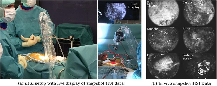
Figure 5. (a) Checkerboard with 48 colour patches used for HSI system validation. (b) Spectrometer setup to acquire reference data.
(c) Snapshot mosaic image of 4C patch with five manually placed circular annotations of 10 pixel radius distributed over the patch for
spectral analysis. The same annotation steps were performed to evaluate the respective linescan data.
Overall, the linescan camera imaging quality is superior to white-balanced data (w − wd )/(ww − wd ). Therefore, no ded-
the one provided by the snapshot camera. However, given its icated system-wide calibration was performed to account for
form factor, a more elaborate mounting mechanism needs to the specific light source intensity spectrum (figure 4) and indi-
be designed to ensure safe and sterile handling of the cam- vidual optical components of the iHSI system—such as optical
era during surgery. Moreover, its comparatively low ima- filters, endoscope adapter and exoscope—during image calib-
ging rate does not allow for HSI data capture without inter- ration.
rupting the surgical workflow which is crucial to provide Both linescan and snapshot camera systems were placed
real-time information for seamless surgical guidance. Nev- at a 35 cm distance to the checkerboard whereby images
ertheless, its imaging characteristics can ensure high-quality were acquired for each patch individually. For each calibrated
HSI in controlled set ups. In contrast, the video-rate snap- hypercube image, five circular regions of 10 pixel radius, dis-
shot camera allows for a compact and sterile iHSI system tributed over the colour patch, were manually segmented for
that can be integrated into surgical workflows using stand- spectral analysis (figure 5(c)).
ard clinical mechanical arm constructions. For reliable tissue Figure 6 provides a comparison between the reference
analysis, image processing methods need to account for the data and spectral information obtained by the iHSI systems
reduced spatial and spectral image resolution in addition to using the linescan and snapshot cameras. It can be seen
lower signal quality that are characteristic for mosaic snapshot that estimated reflectances for both linescan and snapshot
sensors. iHSI systems largely follow the spectrometer reference
measurements. However, especially for higher wavelengths,
a sharp downward trend of estimated reflectances can be
3.3. Checkerboard study: iHSI system verification observed for a few patches (e.g. B4 and H2). Moreover, off-
sets for the snapshot system (e.g. A2 and A6) and for both the
Both the linescan and snapshot camera in section 3.1 were
snapshot and linescan systems (e.g. D2 and G1) can be noticed.
tested in combination with the proposed intraoperative optical
system, i.e. the endoscope adapter and exoscope, to acquire
HSI data in a controlled experiment using a datacolor Spy-
3.4. Ex vivo study: cadaveric veal experiment
derCHECKR checkerboard which comes with 48 colour
patches. For the experiments, the Asahi light source was used An ex vivo experiment using a fresh bovine calf cada-
with the UV-NIR module in combination with the 400 nm ver was performed in a controlled environment to invest-
longpass filter to provide light for 400–1050 nm. Reference igate tissue properties with the iHSI system setup for both
spectra were acquired using an Ocean Optics Maya 2000 Pro linescan and snapshot cameras, performed at Balgrist Univer-
200–1100 nm spectrometer with an Ocean Optics QR600-7- sity Hospital, Zurich, Switzerland. A bovine calf cadaver was
VIS125BX reflectance probe (figure 5). selected because its anatomy approximates that of the human
For the linescan camera, images were acquired using an spine (Cotterill et al 1986).
exposure time of 10 ms and a gain of 1.2. For the snapshot Various tissue types were exposed for tissue analysis
camera, images were acquired using an exposure time of 15 including tendons, muscle, bone, joint capsule, dura and spinal
ms and a gain of 2. Proprietary software was used to provide cord. To achieve optimal orientation and position for imaging
spectrally calibrated hypercube reflectance data for image ana- cadaveric tissue samples, a standard tripod system was used
lysis for both camera systems using the default image calibra- for mounting the iHSI camera systems (figure 7). For both lin-
tion files provided with the cameras as outlined in (Pichette escan and snapshot cameras, secure attachment was achieved
et al 2017). In particular, given an acquired image w and using custom adapter plates with 1/4-20 UNC and 3/8-16
white and dark reference images ww and wd , the calibrated UNC threaded holes (figure 3(b)). An additional Thorlabs
image is obtained by applying a correction matrix C to the DCC3260C RGB camera was used for the experiment to
9J. Phys. D: Appl. Phys. 54 (2021) 294003 M Ebner et al
Figure 6. Comparison of measured reflectance curves between the linescan and snapshot iHSI camera systems and the reference
spectrometer for each of the 48 colour patches. For both linescan and snapshot camera, mean and standard deviation of reflectance
measurements within the manually segmented regions are shown.
provide high-resolution 1936 × 1216 RGB imaging. The cam- white, green and yellow tied together with a nylon thread for
era without optics has a size of 2.9 × 3.5 × 4.4 cm3 and a facilitated handling during the experiment. After positioning
weight of 0.04 kg. Given its C-mount camera lens mount, the first HSI camera (either linescan or snapshot camera) and
it could be used with the same endoscope adapter as part adjusting zoom and focus for imaging the tissue sample, fidu-
of the same iHSI setup. Additionally, its housing comes cials were placed on the tissue to ensure they are within the
with a 1/4-20 UNC threaded hole suitable for attaching quick FOV. Fiducials were then removed from the scene for image
release tripod plates. capture and carefully placed back to avoid anatomical changes
Imaging of the exposed tissue using the three cameras fol- before acquiring a second image with the same HSI camera.
lowed the scheme as summarized in figure 8. By using separate Without touching the scene, the HSI camera was swapped
fiducials which are visible and differentiable across the VIS with the RGB camera using the tripod quick release mechan-
and NIR spectrum it was ensured that images acquired with ism to acquire an RGB image of the tissue sample with fidu-
different cameras could be put in alignment retrospectively. cials. Subsequently, without making changes to the scene, the
We used a set of six pinheads with colours red, black, blue, RGB camera was swapped with the second HSI camera on
10J. Phys. D: Appl. Phys. 54 (2021) 294003 M Ebner et al
Figure 7. (a) Tripod setup with mounted intraoperative HSI (iHSI) system using the linescan camera for ex vivo experiments. A quick
release plate used with standard tripod systems was used to mount linescan, snapshot and RGB cameras using custom adapter plates such as
shown in figure 3(b). (b) Imaging setup during cadaveric veal experiments with orientated camera head for tissue assessment. Labels are
provided to reference anatomical locations for tissue analysis shown in figure 9.
Figure 8. Example sequence of camera system acquisitions during ex vivo imaging to capture HSI data of the spinal cord and rootlets. With
fiducials visible across the VIS and NIR spectrum, alignment between linescan (VIS & NIR) and snapshot (NIR) imagery was achieved
using affine point-based registration for spectral analysis (figure 9).
the tripod. Minor adjustments to camera position, zoom and the linescan camera, a gain of 2 and exposure time of 20 ms
focus were typically needed to ensure the target tissue was in were used. Light intensities were set to 100%, 100% and 50%
focus and the fiducials within the FOV before an image was for the snapshot, linescan and high-resolution RGB cameras,
acquired. After careful removal of the fiducials, another image respectively. Imaging for all cameras was performed with
was acquired of the same scene without making any other room lights switched off and window blinds down to reduce
changes to the setup. For spectral analysis, a neurosurgeon the impact of background light. To ease the imaging work-
(JS) manually annotated relevant tissue types in the pseudo- flow, acquisition of reference data for image calibration was
RGB linescan image, which was obtained by assigning the performed once for both linescan and snapshot cameras in the
channels red, green and blue to the wavelengths of 660, 570 beginning and the end of the experiment, respectively. There-
and 500 nm, respectively. By manually annotating the circular fore, the same white balancing information for each HSI cam-
fiducials, alignment between all images was achieved using era was used for data calibration of all imagery associated with
affine point-based registration (Myronenko and Song 2010). different anatomical locations.
Manual segmentations in the linescan image space were then Figure 9 provides a comparison of estimated reflectance
propagated to the snapshot image space for analysis using the curves between 470 and 740 nm of both linescan and snapshot-
obtained point-based affine registration. based iHSI systems for eight different anatomical scenes, ref-
During the ex vivo experiment, only the VIS mirror module erenced in figure 7(b). For the snapshot camera, only 5 out
was available for the light source therefore providing light of 23 reconstructed bands were available for analysing the
between 385 and 740 nm. For NIR imaging with the snapshot measurements between 670 and 740 nm. In general, relat-
camera, an additional 670 nm longpass optical filter in the fil- ive distribution and qualitative behaviour of reflectance val-
ter wheel of the light source was activated. A gain of 3.01 and ues across tissue types for overlapping spectral bands between
exposure time of 20 ms were used for the snapshot camera for the cameras are well aligned. However, it can be observed
all scenes whereby video imaging was performed to acquire that quantitative measurements of tissue reflectances between
multiple images of each individual static scene. On average, cameras tend to deviate from each other likely due to non-
this led to the acquisition of 18 snapshot mosaic images per uniform white balancing requirements for imaging differ-
scene whose mean image was used for spectral analysis. For ent anatomical sites. In particular, changes in position and
11J. Phys. D: Appl. Phys. 54 (2021) 294003 M Ebner et al
Figure 9. Comparison of reflectance curve measurements between 470 and 740 nm associated with ex vivo tissue sample imaging of eight
different anatomical scenes shown in figure 7(b) using the proposed iHSI system with linescan and snapshot cameras. For each camera, both
the mean and standard deviation of reflectance measurements within the manually segmented regions are shown. Relative distribution and
qualitative behaviour of reflectance values across tissue types between the cameras are well aligned. However, quantitative measurements of
tissue reflectances between cameras generally deviate from each other likely due to different white balancing requirements associated with
imaging multiple anatomical regions during the experiment.
angulation of the camera head needed to capture data of dif- part of a spinal fusion surgery at Balgrist University Hospital,
ferent anatomical sites have likely resulted in different lighting Zurich, Switzerland. The study was approved by the cantonal
conditions and therefore white-balancing requirements which ethical committee (BASEC Nr: req-2019-00939).
was not adequately compensated for using a single pair of ref- Figure 1 presents a schematic of the iHSI setup deployed
erence images. in surgery. In addition to the system components described in
section 3.1 a standard Karl Storz mechanical arm was used
for safe attachment of the iHSI camera system to the surgical
3.5. In patient clinical feasibility case study: spinal fusion
surgery
table using an articulated L-shaped stand (28272HC) via a
clamping jaw (28272UGK). Safe attachment to the snapshot
Following the assessment of the proposed iHSI system for both HSI camera via the VITOM exoscope was achieved via an
linescan and snapshot cameras against design requirements appropriate rotation socket (28172HR) and a clamping cylin-
critical for surgery in section 3.2 in combination with the der (28272CN). Overall sterility of the system was ensured by
quantitative and qualitative assessments in sections 3.3 and autoclaving the mechanical arm, the exoscope and the light
3.4, the snapshot-based system appears suitable for provid- guide before surgery and draping the camera and associated
ing real-time HSI that can seamlessly integrate into the sur- cable.
gical workflow. To test this hypothesis, we conducted an The primary goal of the intraoperative clinical feasibil-
intraoperative clinical feasibility single-patient case study as ity case study was to assess the system’s integration into the
12J. Phys. D: Appl. Phys. 54 (2021) 294003 M Ebner et al
Figure 10. (a) Intraoperative HSI (iHSI) setup during spinal fusion surgery. A live display provides real-time visualisation of snapshot HSI
data. (b) Example snapshot mosaic images of acquired in vivo HSI imagery.
standard surgical workflow. To focus on this objective, we presented which follows strict clinical requirements including
chose to mimic current optical camera systems during surgery sterility and seamless integration into the surgical workflow
and used white light between 385 and 740 nm without the 670 providing capabilities to deliver real-time information with
nm longpass filter12 . For the snapshot camera, a gain of 4 potential for intraoperative surgical guidance.
and exposure time of 20 ms was chosen with the light source Towards reaching this goal, here we present system design
providing 100% of light intensity. A laptop running custom- requirements of an HSI system critical for intraoperative sur-
ized software for real-time interaction with the camera system gical guidance suitable for open surgery. However, given the
and data visualisation was placed onto a trolley at a safe dis- design of the system, straightforward adaptation for endo-
tance outside of the sterile environment. Connection to a mon- scopic surgery is possible. We investigate two state-of-the-
itor in the OR provided a live display of captured video-rate art industrial HSI camera systems, based on either linescan
HSI data (figure 10(a)). In particular, this allowed for instant or snapshot technology, and assess their suitability for sur-
feedback to and interaction with the surgical team for adjust- gical use. Based on our established criteria, we present an
ing camera position and orientation in addition to endoscope intraoperative HSI system and perform a scoring against these
adapter settings to acquire in-focus data for the region of sur- requirements by considering both HSI cameras. We performed
gical interest. Using this setup, in vivo imaging was performed controlled checkerboard experiments demonstrating that reli-
at eight different stages during surgery to acquire HSI data of able reflectance measurements can be obtained with the pro-
various tissue types including skin, adipose tissue, scar tissue, posed system using both HSI cameras. However, quantitative
fascia, muscle, bone, pedicle screws and dura (figure 10(b)). experiments underline that a more refined calibration model
Imaging of each anatomy lasted between 6 s and 44 s with needs to be deployed that accurately describes the intraoperat-
minimal disruption to the surgical workflow. After successful ive optical system for more precise reflectance measurements.
surgery with seamless transitions to acquire HSI data, a final A series of ex vivo experiments were performed to investig-
recording of 3 min 16 s was performed to capture imaging data ate reflectance properties for a range of tissue types includ-
covering the surgical cavity. ing tendons, muscle, bone, joint capsule, dura and spinal cord
with both iHSI camera setups mounted on a standard tripod
system allowing for versatile imaging configurations in a con-
4. Discussion and conclusion
trolled environment. In particular, this proved to be a suit-
Previous work has underlined the potential of HSI for intraop- able setup for the linescan camera to provide high-resolution
erative tissue characterisation as a non-contact, non-ionising, data in both spatial and spectral dimensions across the VIS
non-invasive and label-free imaging modality. Despite and NIR spectrum for ex vivo tissue analysis. The iHSI sys-
numerous research studies exploring the clinical potential tem allowed for seamless and safe transitions during various
of HSI for surgery, to our knowledge, no HSI system has been stages of spinal fusion surgery and acquired video-rate HSI
data of multiple tissue types including skin, adipose tissue,
fascia, muscle, bone, pedicle screws and dura. Our successful
12 While theoretically possible to obtain quantitative results for up to five clinical feasibility case study demonstrated that the proposed
bands of the NIR camera with the available VIS light source, the requirement iHSI system seamlessly integrates into the surgical workflow
of the 670 nm longpass filter would have resulted in unconventional, and for
by respecting critical clinical requirements such as sterility and
the surgical team potentially distracting, red light during surgery. Given the
limited value of, at most, five spectral bands and the desire to minimize the is capable of providing wide-field video-rate HSI imagery. By
risk profile for the patient during surgery, we decided to perform the workflow developing a data-driven information processing pipeline we
study using familiar white light. believe such video-rate HSI data can be utilised to provide
13J. Phys. D: Appl. Phys. 54 (2021) 294003 M Ebner et al
real-time wide-field tissue characterisation for intraoperative systems (Langer et al 2020) and would ensure parity with cur-
surgical guidance. rent microscopic standards (Schwiegerling et al 2015). Further
Because of technical limitations and consideration not to experiments will be performed to investigate the accuracy at
alter the view of the surgeon, only visible light between 385 which tissue margins can be identified. While at least 3 pixels
and 740 nm was available for use in the ex vivo and in vivo per millimetre are a necessary requirement to provide at least 1
studies at Balgrist University Hospital. Given that the snap- mm precision for margin differentiation, the ability to resolve
shot NIR camera operates between 665 and 975 nm only 5 out tissue boundaries also depends on light diffusion effects in tis-
of 25 acquired spectral bands could be used for image ana- sue which may additionally vary in between different organs
lysis. Computational simulations not presented in this study and anatomies.
suggested that these five reconstructed bands can still provide Our in vivo clinical feasibility case study demonstrated that
accurate reflectance information but may be less reliable for our iHSI device integrated well into a standard surgical work-
higher wavelengths within this range. Furthermore, only the flow and was capable of capturing HSI data. Overall, members
default calibration files associated with each camera were used of the surgical and theatre team found the system straightfor-
for this study to reconstruct reflectance data using the propriet- ward to use although routine training will need to be imple-
ary software. In particular, the specific spectrum of the Xenon mented to ensure smooth operating during surgery. The cur-
light source was not taken into consideration. Given the stark rent hardware setup and draping requirements posed no safety
non-uniformities especially in the NIR region greater than 800 concerns to team members and the system’s size, weight and
nm (figure 4) inaccuracies are to be expected. In addition, spa- portability were acceptable in maintaining a smooth surgical
tial changes in illumination due to, e.g. vignetting and optical workflow. Some team members commented that having to dim
changes induced by different zoom and focus settings of the the lights to acquire HSI was a little limiting. Further work to
endoscope adapter were not taken into account. Moreover, provide on-the-fly image calibration crucial to acquire inter-
despite demonstrating the suitability of our proposed tripod- pretable and quantitative HSI data that can deal with chan-
based iHSI system setup for ex vivo tissue analysis experi- ging light conditions in the OR during surgical procedures
ments, the quantitative reflectance measurements presented as such as recently proposed in Ayala et al (2020) is therefore
part of this study are likely to be confounded due to imprecise in progress. Additionally, we intend to conduct further in-
white balancing. In particular, this illustrates the difficulty to patient intraoperative studies with a larger number of patients
acquire reliable calibration data in practice to acquire quant- to fully assess and appraise the use of our iHSI device during
itative HSI data for different imaging scenarios, especially surgery.
during surgery. However, qualitative behaviour of reflectance
measurements captured for multiple tissue types may still per-
sist due to good qualitative correlation between radiance meas- Data availability statement
urements and calibrated reflectance measurements.
Future work includes further characterising the optical The data that support the findings of this study are available
components of the iHSI setup to achieve more accurate upon reasonable request from the authors.
calibration models. In particular, this includes the optical
subsystem consisting of exoscope and endoscope adapter for
different zoom and focus settings. Moreover, further compu- Acknowledgments
tational algorithms will be developed to reconstruct real-time
hypercube data from spatially and spectrally undersampled This work was supported by core funding from the
characteristic for snapshot mosaic imaging. Building on the Wellcome/EPSRC [WT203148/Z/16/Z; NS/A000049/1;
NIR snapshot camera, this can be used to provide real-time WT203145Z/16/Z; NS/A000050/1]. This project was sup-
information on blood perfusion and oxygenation saturation ported by the National Brain Appeal [NBA/T&I/N-ONC]
which can help, e.g., to differentiate healthy from necrotised and the Royal Academy of Engineering under the Enter-
tissue during gastrointestinal surgery. The proposed ex vivo prise Fellowship scheme [EF2021\10\110]. This project has
setup can be used for further experiments to acquire both high- received funding from the European Union’s Horizon 2020
resolution linescan and low-resolution snapshot HSI data. research and innovation programme under grant agreement
This can provide crucial information for developing real-time No 101016985 (FAROS project). ME, JS, SO and TV are
demosaicking and tissue differentiation methods for snapshot shareholders of Hypervision Surgical Ltd London, UK, and
HSI. have an equity interest in the company. TV is a shareholder of
Additional experiments should be based on a snapshot sys- Mauna Kea Technologies, Paris, France.
tem that operates in the VIS range instead. Indeed, given our
setup, any compact camera that follows camera dimension and
weight requirements as outlined in table 1 can be integrated ORCID iDs
into the proposed iHSI system setup in a straightforward man-
ner. It would also be beneficial to enable HSI acquisition with Michael Ebner https://orcid.org/0000-0002-0170-7062
a variable working distance, field of view, depth of field and Jonathan Shapey https://orcid.org/0000-0003-0291-348X
depth of focus (table 2) which in turn would enable the device Yijing Xie https://orcid.org/0000-0002-3432-8587
to be integrated with various commercial exoscopic surgical Mazda Farshad https://orcid.org/0000-0002-7190-1127
14You can also read