CEEP1115 - | energy.gov.au
←
→
Page content transcription
If your browser does not render page correctly, please read the page content below

CEEP1115

Milestone 9 Final Report
Frankston Arts Precinct
Trigeneration

                   This activity received funding from the Australian Government.

                  The views expressed herein are not necessarily the views of the
                Commonwealth of Australia, and the Commonwealth does not accept
                   responsibility for any information or advice contained herein.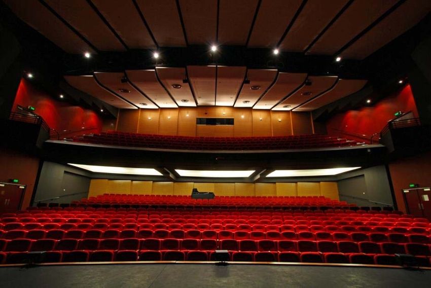
TABLE OF CONTENTS

Contents
Definitions                                                                                                       4
EXECUTIVE SUMMARY                                                                                                 5
SITE OVERVIEW                                                                                                     7
PROJECT ENERGY EFFICIENCY ACTIVITIES                                                                              9
PROJECT OVERVIEW                                                                                                 10
PROJECT OBJECTIVES                                                                                               16
  Project Energy Efficiency Activities                                                                           17
  Trigeneration                                                                                                  23
     Ener‐G Co‐generation (CHP) system                                                                           23
     Absorption Chiller                                                                                          27
     Switchboard – Central Control System                                                                        28
  Microgeneration                                                                                                29
     BlueGen                                                                                                     31
     Yanmar                                                                                                      34
     Qnergy                                                                                                      38
PROJECT DEMONSTRATION AND COMMUNICATIONS ACTIVITIES                                                              39
  Thermal Comfort Guidelines                                                                                     40
  Viewing Display area                                                                                           41
  Real time energy display system                                                                                42
  Signage                                                                                                        45
  Community Energy Saving Workshops                                                                              47
  Flytower Projector Screen                                                                                      49
  Community and Industry tours                                                                                   50
  Fact Sheet / Tour notes                                                                                        50
  Media                                                                                                          50
OUTCOMES AND BENEFITS OF THE PROJECT                                                                             50
  Project Energy Efficiency Improvement Template                                                                 51
  Energy Efficiency savings to date                                                                              52
  Issues and challenges                                                                                          53
BUDGET                                                                                                           54
PROJECT OPERATION, MECHANISMS AND PROCESSES                                                                      55
CONCLUSION                                                                                                       56

                                                   CEEP1115 Frankston City Council Final Report (Milestone 9) Page | 2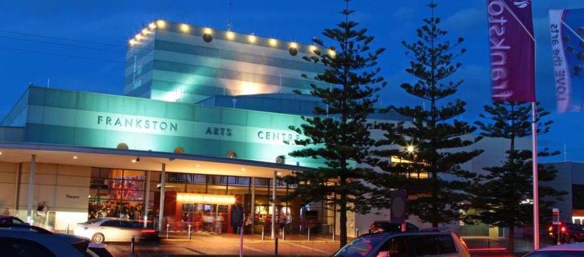
Frankston Arts Centre view from Cube 37

                                          CEEP1115 Frankston City Council Final Report (Milestone 9) Page | 3
DEFINITIONS
BMS                Building Management System (HVAC, lighting controls)
CEEP               Community Energy Efficiency Program (the Grant)
CHP                Combined heat and power unit, also known as a cogeneration unit
CO                 Carbon Monoxide
Cogen              Cogeneration system – gas powered generator that produces electricity and heat on site
COP                The coefficient of performance or COP (sometimes CP) of a heat pump is a ratio of heating
                   or cooling provided to electrical energy consumed. Higher COPs equate to lower operating
                   costs.
CTs                Current transformers
FAC                Frankston Arts Centre
FCC                Frankston City Council
Fuel Cell          A fuel cell is a device that converts the chemical energy from a fuel into electricity through a
                   chemical reaction with oxygen or another oxidizing agent
Genset             The cogeneration unit
GHG                Greenhouse gases
HVAC               Heating Ventilation and Cooling System
ISOQAR             ISOQAR is an accredited certification body. This means that ISOQAR is
                   accredited to audit organisations against a variety of ISO management
                   standards. On a day‐to‐day basis, this work is regulated by the ANSI‐ASQ
                   National Accreditation Board (ANAB).
                   ISOQAR is an independent, third‐party certification body without affiliation to any other
                   company or organization. It assesses a wide range of manufacturing and service
                   organizations, both throughout the US and across many parts of the world.
Microgen           Micro generators in the form of BlueGen, Yanmar and Qnergy systems
MSB                Mechanical Switch Board
NOx                Nitrous oxide
Precinct           Frankston Arts Precinct including FAC, Library, Youth Resource Centre, Carpark and Cube 37
                   Gallery. Cube 37 was logistically unable to benefit from the trigen output at this stage.
Redundancy         Can work independently of complimentary system (e.g. HVAC can run independently of
                   Trigeneration system if required)
SOFC (Solid        A solid oxide fuel cell (or SOFC) is an electrochemical conversion device that produces
Oxide Fuel Cell)   electricity directly from oxidizing a fuel. Fuel cells are characterized by their electrolyte
                   material; the SOFC has a solid oxide or ceramic, electrolyte. Advantages of this class of fuel
                   cells include high efficiency, long‐term stability, fuel flexibility, low emissions, and relatively
                   low cost. The largest disadvantage is the high operating temperature which results in longer
                   start‐up times and mechanical and chemical compatibility issues
Trigen             Trigeneration system – includes a cogeneration system and an absorption chiller
Turnkey            A complete system, ready to go (turn the key)
VSD                Variable Speed Drives

                                                            CEEP1115 Frankston City Council Final Report (Milestone 9) Page | 4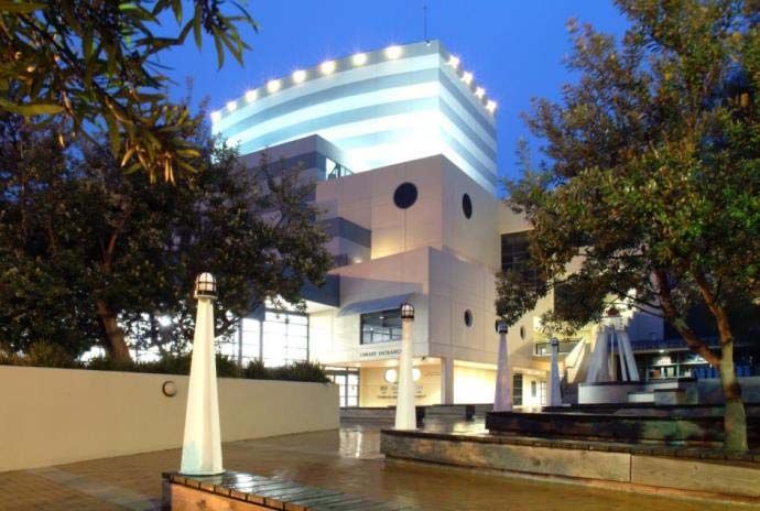
EXECUTIVE SUMMARY
The Frankston Arts Precinct trigeneration and microgeneration project showcases alternative energy and reduce
carbon emissions for the Frankston Arts Precinct (the Precinct), which includes the Frankston Arts Centre (FAC); Cube
37 Gallery, Library and Youth Resource Centre. During the project, it was ascertained that Cube 37 was deemed
unviable to be connected to the trigeneration output at this stage.
The main purpose of the project was to reduce greenhouse gas emissions. As Council’s highest energy user, the
Frankston Arts Precinct’s energy use is also a significant contributor to Council’s overall greenhouse gas emissions. The
Community Energy Efficiency Project aimed to help local government reduce greenhouse gas emissions. Additional
benefits of the project will be ongoing operational savings and capacity building of the community by showcasing
innovative alternative technologies in a local situation.
As Frankston City Council’s highest energy user, the FAC contributes significantly to Council’s greenhouse gas
emissions, energy usage and costs. The Precinct was identified in Council’s Alternative and Renewable Energy Study
(Enhar, 2011) as a suitable candidate for trigeneration. Further studies included CarbonetiX 2009 Energy Efficiency
audit and Recommendations, and Mito Energy Feasibility Study (2012).
The project aims to reduce pressure on the electricity grid, particularly during peak times such as heatwaves, and
reduce Council’s dependence on brown coal generated electricity which has a high carbon coefficient; and contribute
towards Council’s Carbon Neutral 2025 target, alternative energy target and annual emissions targets of 12,254 to
11,794 tonnes CO2‐e over the next few years.
With the CEEP grant, Council was able to install a 120kW‐e trigeneration engine, thermal and absorption chiller, and
three microgeneration units – BlueGen Fuel Cell, Yanmar internal combustion engine and a Qnergy sterling engine.
Installations occurred in the latter part of 2014 and early 2015.
Cogeneration is more efficient than sourcing electricity from brown coal due to the amount of grid losses with
traditional electricity and the ability to capture waste heat from a cogeneration system and utilise it for both heating
and cooling (trigeneration). Coupling Trigeneration (Cogeneration + chiller) with the microgeneration system (hot
water) essentially creates “quad generation” in that there are four key outputs from the overall integrated systems:
Electricity, Heating, Cooling and Hot water.
A comprehensive communications strategy was implemented to advise and engage users on the works being done, to
encourage behaviour change to support energy conservation initiatives, and embrace alternative electricity
generation as an acceptable energy efficiency option.
Overall objectives were to:
Reduce energy consumption and GHG emissions of the building by 704 tonnes of CO2‐e per annum, 42%
reduction in GHG emissions from grid energy demand and grid electricity savings of $41,270
Contribute towards Council's Carbon Neutral 2025 target, alternative energy target and annual targets of
11,794 tonnes CO2‐e by 2016/17.
Future proof the precinct against climate change and blackouts/brownouts during heatwaves
Showcase alternative energy sources in small and large scale with a world first comparison display of
microgen systems
CEEP1115 Frankston City Council Final Report (Milestone 9) Page | 5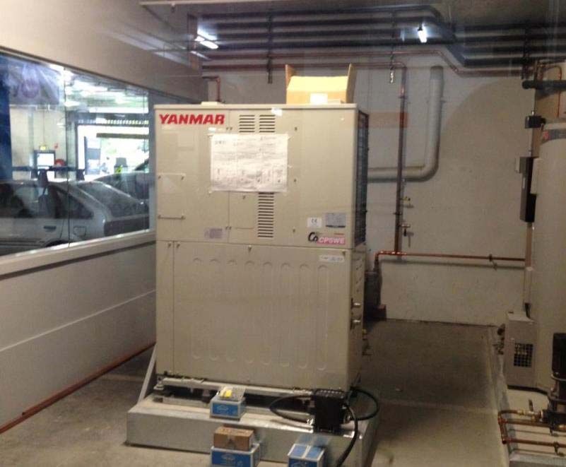
A range of technologies were used to achieve the project objectives including:
Trigeneration
Absorption chiller
BlueGen Fuel Cell
Yanmar microgeneration system
Qnergy sterling engine
A range of communication and education activities supported the project and its promotion including:
Development and implementation of the Heating and Cooling Policy, known as the Thermal Comfort
Guidelines
Installation of a real time energy display system
Educational Projector show about the project
Meetings, emails and briefings
Councillor bulletins; Media Release about the project; Energy efficiency articles in local media/newsletters
Sustainable Homes “Energy Busters” Workshops for the Frankston City community.
Energy performance outcome monitoring will commence once the system is completely operational in April.
A range of social benefits are already apparent with improved energy efficiency awareness and positive feedback from
community workshops. Staff awareness of energy usage of the precinct has also improved, and staff knowledge of the
emerging technologies and energy efficiency options for Council facilities has also resulted from their involvement
with the project.
Council encountered issues with timing and budget due to the technical complexities of the project, and the
outsourcing of project management for part of the project. This caused several delays and required Council to
contribute additional funding. A Deed of Variation and several milestone extensions were granted to assist with this.
The project was over‐budget due to costs coming in higher than estimated at the time of applying for the CEEP grant
(many tenderers up to double). CPI increases from the grant being written to being awarded and delivered also
impacted the budget.
The initial project budget was $1,011,241 with $486,035 being contributed by the Australian Government. The total
project cost was $1,079,221 with Council making up the additional $67,980. Once grant funds have been received, the
budget breakdown will be:
Total project (preliminary figures): $1,079,221 = Australian Government $486,035 + Council contribution $593,186.
CEEP1115 Frankston City Council Final Report (Milestone 9) Page | 6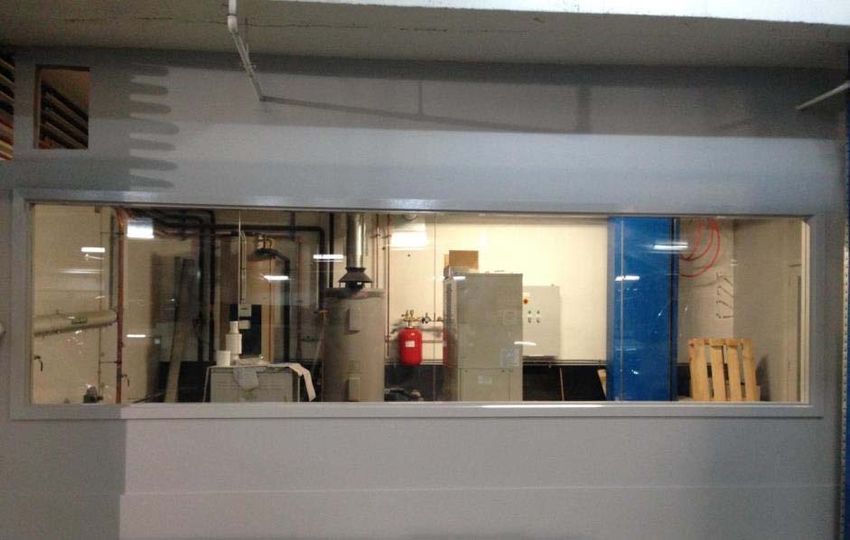
SITE OVERVIEW
The Frankston Arts Centre is a landmark theatre and art gallery located on Davey Street Frankston, Victoria.

The Centre provides community access with workshops, exhibitions, shows, conferences and expos, and youth art
projects running throughout the year. It plays host to a number of major performances, including regular shows by the
Melbourne Symphony Orchestra and Victorian Opera, and is a tour venue for the Melbourne International Film
Festival, Opera Australia and a number of national theatre companies.
The Centre houses an 800 seat theatre boasting the second largest proscenium arch stage in Victoria, a 60 line fly
tower and state of the art technical and staking equipment.

                                                         CEEP1115 Frankston City Council Final Report (Milestone 9) Page | 7
Above: Frankston Arts Precinct. Below: Frankston Arts Centre floorplan

                                                       CEEP1115 Frankston City Council Final Report (Milestone 9) Page | 8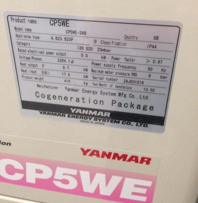
Below: the 800 seat theatre
PROJECT ENERGY EFFICIENCY ACTIVITIES
Frankston City Council prepared this project to install a trigeneration system, based on recommendations from the
Entura Alternative and Renewable Energy Study for Frankston City Council.
After an intensive engineering review process, the final plant consisted of:
ENER‐G E‐125 gas generator (Trigen unit) with Rated electrical output 124 kW and Rated heat output 200
kW. Maximum fuel consumption at rated capacity 36 Nm3/hr
Shuangliang Eco‐Energy Co. Ltd absorption chiller RXZ(92/84)‐14(12/8)(29.5/35)H2 with Rated thermal
output 135 kW cooling capacity and coefficient of performance of 0.75
BlueGen micro‐generator Rated electrical output 1.5 kWe, rated heat output 0.61 kW, maximum fuel
consumption at rated capacity 9.5 MJ/hr
Yanmar Micro CHP 3.9kW lean‐burn Miller Cycle engine
Qnergy external combustion 7.5kW Stirling engine
Customised Real time energy display system
This was coupled with the communications program referred to in this document.
CEEP1115 Frankston City Council Final Report (Milestone 9) Page | 9
Below: ENER‐G Cogeneration system – standard enclosure and internals.

Below: Shuangliang Absorption Chiller Illustration

PROJECT OVERVIEW
This innovative, high profile project will set the 'jewel in the crown' for investing in best practice and cutting edge
alternative technology for Melbourne. It will provide a showcase demonstration site for best practice on‐site
decentralised efficient energy supply, in line with smart grid onsite generation opportunities. Trigeneration and micro
generation fuel cell technology fits in with the 'big picture' smart grid vision currently being explored by Jemena and
United Energy. The microgeneration component has been designed to be replicated in residential urban
developments and other facilities.
The project creates functional and feasible electricity demand reduction for the Arts Precinct, and is intended to be
displayed in a way that does not interfere with the access to the Arts Centre when in use when tours are run, such as
the display board will be located in the public access foyer area and the microgeneration is intended to be placed
behind a glass wall for easy tour access but not obstructive. The vision is intended to not only inspire other
organisations to explore cutting edge high tech solutions to reducing emissions, but engage with the entire
community such that school students may be inspired to pursue a future in science and engineering from gaining an
understanding of high tech sustainability solutions.

                                                        CEEP1115 Frankston City Council Final Report (Milestone 9) Page | 10
The Precinct was selected as it is Council's highest energy user. The site has previously undergone extensive energy
efficient retrofits to reduce energy usage (4.5% reduction in the last quarter compared with the same time in the
previous year).
The Precinct also has a high public profile and is the perfect opportunity to 'showcase' a trigeneration system to the
public, other councils and large organisations who could benefit from replicating the project.
The Frankston Arts Centre is a significant consumer of energy, consuming approximately 1.2GWh of coal fired grid
electricity and 3,374 GJ of natural gas annually (2011/12).
These two energy sources are subject to a range of external economic, environmental and reliability pressures and
risks, including:
Increased pressure on the aging grid infrastructure leading to brown outs and blackouts, impacting our
community’s most vulnerable citizens
Revenue loss from electricity interruptions
Significant increases in power supply costs
Low efficiency conversion and use of grid power sources
Overall social responsibility to reduce Council’s carbon footprint and contribution to climate change, which is
already impacting the Frankston municipality through coastal erosion and storm surge, increased heatwaves
and average temperatures, impacts on wildlife and native vegetation, and increased droughts and flooding
events.
On average, the FAC operates between 9am and 5pm on weekdays and weekends, as well as afterhours shows and
events. Based on this energy use profile, it was recommended by consulting engineers on the project to operate the
trigeneration system 15 hours a day, five to seven days a week.
The proposed trigeneration plant was designed to provide Council with greater control over the site’s energy supply,
reduce pressure on the grid during peak times and heatwaves, and improve reliability of operations through
guarantees of supplies and redundancy. It will also assist the stabilisation of energy costs and a higher conversion
efficiency of energy used. It will make significant reductions to both Frankston City Council’s carbon emissions, but
Australia’s as well.
Project Stages
Feasibility (pre‐grant):
Precinct was identified in Council’s Alternative and Renewable Energy Study (Enhar, 2011)
CarbonetiX 2009 ‐ Energy efficiency audit and recommendations
Mito Energy Feasibility Study (2012) including preliminary concept design and preliminary cost benefit
Grant application
Design:
Detailed system design and sizing both cogeneration unity and absorption chiller to fit the Precinct’s electrical
and thermal requirements
Detailed design for hydraulic circuits for integration with existing heating water systems
Complete detailed design of the system’s electrical circuits for integration into the main switchboard inclusive
of electrical schematics for energy authority approvals
CEEP1115 Frankston City Council Final Report (Milestone 9) Page | 11 Complete electrical and gas regulatory submissions and approvals
Civil Works:
Construct a plant room structure with large roller doors on either side for housing the trigeneration system.
Plant room 4m wide, 7.5m long, 2.5m high and bolted to concrete roof
Complete penetrations through the roof for cogeneration unit exhaust system, ventilation system and
cooling tower
Obtain development approvals for all related civil works
Design and install roof reinforcement (unplanned variation)
Install chiller and cogeneration unit (trigen)
Mechanical:
Complete all gas and water pipework, installation of pumps, valves and heat exchangers, ducting and
ventilation and assembly of the cogeneration system as described in drawings
Disconnect plumbing services from old chiller plant on roof plant room and assist in removal by crane
operator
Crane plant to roof area and position all trigeneration plant
Supply and install vertical pipe support posts to clip relevant plumbing services to within plant area
Plumb in new natural gas supply line from existing. Connect new gas fitting line to tri‐generator with isolator
OPSO regulator and tested to current gas regulations
Supply and install all plumbing between the cogeneration unit, absorption chiller and cooling tower including
all heat exchanges and pumps
Supply and installation of 20mm cold water supply to new cooling tower from existing 25mm supply in plant
area
Assemble and erect flue with silencer, supply and install a flue support bracket
Plumb in 65mm chilled waste lines from absorption chiller and connect to existing building chiller system on
the roof plant area
Supply and install new 50mm copper heating hot water flow and return lines from PXH1 heat exchanger and
cut into the building heating hot water return line. Full insulation of all lines.
Pressure test all new services to current regulations
Supply and install 15mm auto air bleeds at high points of the system and drain valves where required.
Pipe Extension:
Plumb in new 50mm 10Kpa copper natural gas supply line from existing gas meter room to serve new plant
room only
Extend through the building and connect to tri generator with required valving and marking
Electrical:
CEEP1115 Frankston City Council Final Report (Milestone 9) Page | 12 Design and install all associated electrical engineering
Supply and install main power feeder XLPE cables and earth (95mm) from genset to MSB
Supply and install communications cables from genset to MSB
Install and connect power modulation cable
Supply and install current transformers to MSB
Supply and install all wiring to cogeneration unit control panel
Supply and install all wiring to trigeneration control board
Supply and install all wiring to trigeneration switch board
Supply and install 16mm 4 core and supply to trigeneration switch board
All labelling as required
Commissioning of installation
Installation of Microgen units:
Relocate hot water services
Supply and install power feed for sub switchboard in ground floor carpark
Supply and install power circuit outlets
Connect microgen units to supply with separate isolators
Supply and install communications cable area for internet connection
Integrate microgens mechanically with site’s existing systems
Installation of the real time energy performance monitoring system
Below: View of the Frankston Arts Precinct from Playne Street, showing the Library on the left, Arts Centre and
Flytower in the centre, and Youth Resource Centre and Conference rooms to the right.
CEEP1115 Frankston City Council Final Report (Milestone 9) Page | 13Data Analysis:
In order to optimise the trigeneration system, sizing was critical to the success of the project. Appropriate selection of
the equipment allows integrating with the building’s electrical and thermal profile. This process helps to improve the
efficiency, longevity and maximises potential financial savings of the cogeneration plant. If the unit is undersized then
the maximum benefit is not being achieved. If oversized, the unit will frequently modulate, significantly increasing
maintenance costs or rejecting too much thermal energy, reducing efficiency of the unit.
Note: Data is based primarily on the Frankston Arts Centre as the highest energy user of the Frankston Arts Precinct.
Data analysis and ground proofing of infrastructure deemed that Cube37 should not be connected to the trigeneration
system. In the future, excess heat from the system may be used at Cube37 if infrastructure allows.
Below: Daily analysis of maximum, minimum and average load profile
The FAC’s peak electrical load is 440kW and the average electrical consumption is 213kW.
CEEP1115 Frankston City Council Final Report (Milestone 9) Page | 14Number of readings (sorted)
The graphs are based on interval data of half hour electrical demand, over 15 hours a day, 5 days a week. The graph
represents instantaneous electricity as a curve (blue line) with electricity consumption on the vertical axis and reading
number on the horizontal axis with these readings reordered from highest to lowest in order to illustrate:
Total electrical consumption (total area under the curve)
Peak consumption (left hand side of the curve)
Base load of the site and the amount of power supplied by the cogeneration system.
The green line represents the cogeneration electrical production. The amount of demand that can be satisfied by the
cogeneration system is represented by the area under the green curve. The red line indicates the new load profile of
the FAC after installing the complete trigeneration system due to chiller offset. The cogeneration line drops off at low
electricity demand as the unit will not be operated at less than 50% of its rated capacity.
3D schematic of location (Illustrated below)
The trigeneration system is located on the roof level
plant room of the FAC. The layout is demonstrated
below. The entire trigeneration system is located
between the Powerpax adiabatic chiller (bottom left
box) and the building ventilation outlet (top right box).
The positioning was extremely tight as the plant room
is limited for space. The diagram below shows the
cogeneration unit (long white unit – top right),
absorption chiller (blue unit – bottom right), Cooling
tower (white cube with wide exhaust on left hand
side), pumps, piping and heat exchangers. All of these
items had to fit where the existing York chiller was
located prior to removal for the project.
CEEP1115 Frankston City Council Final Report (Milestone 9) Page | 15PROJECT OBJECTIVES
Frankston City Council’s project aimed to improve the energy efficiency of the Frankston Arts Precinct. The anticipated
outcomes from this project included a reduction in energy expenditure, pressure on the grid, air pollution and
greenhouse gas emissions. Additional project outcomes included the trial of innovative technology in a world first trial
to demonstrate the infrastructure side by side to encourage the adoption of improved energy management practices
within councils, organisations and the broader community.
Additional benefits were to provide better services for the community facility by reducing pressure on the grid leading
to brown outs and black outs, minimising energy consumption and costs to manage the impacts of the carbon price
and rising energy costs compared with business as usual, build knowledge and capacity of the energy services and
construction industry around the microgeneration demonstration trial site, support competitive Australian energy
efficiency technology and equipment manufacturers, in particular BlueGEN, and of course to contribute to the
national effort to reduce greenhouse gas emissions.
The primary objectives of the project were to:
Reduce energy consumption and GHG emissions of the building by 704 tonnes of CO2‐e per annum, 42%
reduction in GHG emissions from grid energy demand and grid electricity savings of $41,270
Contribute towards Council's Carbon Neutral 2025 target, alternative energy target and annual greenhouse
target of 11,794 tonnes CO2‐e by 2016/17
Future proof the Precinct against climate change and blackouts/brownouts during heatwaves
Showcase alternative energy sources in small and large scale with a world first comparison display of
microgen systems
The broader project objectives were to showcase alternative energy and reduce carbon emissions for the Frankston
Arts Precinct, which includes the Frankston Arts Centre, Cube 37 Gallery, Library and Youth Resource Centre. As
Council’s highest energy user, the FAC contributes significantly to Council’s greenhouse gas emissions, and contribute
towards our Carbon Neutral 2025 target, alternative energy target and annual greenhouse gas emissions targets of
12,254 to 11,794 tonnes CO2‐e in the next few years.
The Precinct was identified in Council’s Alternative and Renewable Energy Study (Enhar, 2011) as a suitable candidate
for trigeneration. Further studies included CarbonetiX 2009 ‐ Energy efficiency audit and recommendations, and Mito
Energy Feasibility study (2012).
The project aimed also to reduce pressure on the electricity grid, particularly during peak times such as heatwaves,
and reduce Council’s dependence on brown coal generated electricity which has a high carbon coefficient.
With the CEEP grant, Council was able to install a trigeneration system including absorption chiller, and showcase
three micro generation units in a world first comparison trial, consisting if a BlueGen fuel cell, a Yanmar engine and a
Qnergy Stirling unit.
A comprehensive communications strategy was implemented to advise and engage users on the works being done, to
encourage behaviour change to support energy conservation initiatives, and embrace alternative electricity
generation as an acceptable energy efficiency option.
Project overview:
Utilise the gas‐fired trigeneration plant to power the facility, as well as provide heating and cooling. This will
significantly reduce the amount of electricity required to run the facility.
In order to showcase the trigeneration and high efficiency fuel cell system to the community, they will be
incorporated into the regular tours of the Arts Centre that are currently run.
CEEP1115 Frankston City Council Final Report (Milestone 9) Page | 16 Installation of the trigeneration and microgeneration plant aims to reduce electricity use and greenhouse gas
emissions in the Precinct by the following:
Tri‐generation system potential savings evaluation:
Estimated Net annual cost savings $34,772 ex GST
Estimated Simple payback (excluding annualised maintenance costs) 14.4 years
Estimated GHG Savings 622 CO2–e tonnes per annum
Estimated GHG percentage saving 34% (against 2011/12 emissions generated by the Precinct)
Micro‐generator potential savings evaluation:
Estimated Net annual cost savings $6,498 ex GST
Estimated GHG Savings 82 CO2–e tonnes per annum
Estimated GHG percentage saving 4% (against 2011/12 emissions generated by the Precinct)
This equates to total savings of:
Estimated Net annual cost savings $41,270 ex GST
Estimated GHG Savings 704 CO2–e tonnes per annum (electricity only – excludes gas emissions)
Estimated GHG percentage saving 38% (against 2011/12 total Precinct emissions) – electricity only
Anticipated outcomes:
a) Deliver strong investment returns through future cost savings, reduced impact of uncontrolled external
electricity price increases, greater efficiency and increased monitoring and scrutiny of energy production and
consumption.
b) Encourage more generalised improved energy management within the Precinct by creating awareness of
energy efficiency initiatives by recording and reporting energy demand reductions and efficiency
improvements.
c) Expand the community’s understanding of the potential for energy efficiency and CO2 abatement
improvement opportunities. Create awareness of the cost savings that could be derived along with the
reduced CO2 emissions through implementation of energy efficient technology and alternative energy.
Project Energy Efficiency Activities
The technologies used were selected as they were the leading products on the market at the time of undertaking the
project, offering great ‘bang for buck’ and long term energy savings without compromising on quality.
The technologies selected were also to showcase emerging technology in microgeneration, which can be
demonstrated and replicated on small and large scales, offering excellent community and industry engagement
opportunities and a world‐first trial to run the three different units side by side for comparison.
Cogeneration is more efficient that sourcing electricity from brown coal due to the amount of grid losses with
traditional electricity and the ability to capture waste heat from a cogeneration system and utilise it for both heating
and cooling (trigeneration). Coupling Trigeneration (Cogeneration + chiller) with the microgeneration system (hot
water) essentially creates “quad generation” in that there are 4 key outputs from the overall integrated systems:
Electricity, Heating, Cooling and Hot water.
CEEP1115 Frankston City Council Final Report (Milestone 9) Page | 17How combined Trigen and Microgen works
Estimated System Outputs
CEEP1115 Frankston City Council Final Report (Milestone 9) Page | 18Assuming the tri‐generation system runs for 15 hours per day, 5 days a week:
Annual kWh produced – Cogeneration 476,160 kW of electricity
Annual kWh produced Microgen 5760 kW of electricity
Annual CHW produced 576,000 kW of cooling
Annual HHW produced 768,000 kW of hot water
Estimated system carbon offset KgCO2‐e/annum 524 tonnes (704 tonnes excluding gas emissions)
Annual carbon offset micro Gen KgCO2‐e 66 tonnes
Annual electricity consumed (kWh) 15,936kW
Annual oil consumed (Litres) Negligible
Annual gas consumed (GJ) 5294.59 GJ
The System
The equipment that makes the trigeneration system operate is a CHP (cogeneration) unit, an absorption chiller, two
heat exchangers (a heating heat exchanger and a heat rejection plate heat exchanger) as well as associated pumps
and control valves. In addition 3 microgeneration units were installed to supply further electricity and hot water to the
site, without the large carbon emissions.
Below: Single line diagram of the trigeneration system
CEEP1115 Frankston City Council Final Report (Milestone 9) Page | 19Below: Trigeneration system schematics
Daily operations
The cogeneration unit is primarily operated on a time clock for 15 hours a day (7am to 10pm daily) which reflects the
high peak and shoulder electrical tariffs on weekdays.
The unit can be operational from 50‐100% of its capacity. When the system fires up, it synchronises with the grid and
takes over the electrical feed of the centre through a parallel grid connection. If the load on the centre is above the
amount supplied by the cogeneration and microgeneration units, the additional electricity required is imported from
the grid. If the load on the centre drops below 50% of the capacity of the cogeneration unit, the unit unloads power to
the grid and the grid takes up the excess load of the building.
The cogeneration system can also be remotely started or stopped by the Building Management System (BMS) and a
manual on/off control within the cogeneration unit. These systems gradually unload the electricity off the generator
to a final system stop. This is known as a soft stop. The system also has a hard stop, or emergency stop, for when the
emergency stop button is pushed, or if a serious error or fault signal from the engine is detected. If this occurs, the
CEEP1115 Frankston City Council Final Report (Milestone 9) Page | 20generator circuit breaker (GCB) is instantly opened allowing the generator to slow to a stop. In this instance the
building is powered from the grid.
All other components of the trigeneration system rely on the cogeneration unit being operational.
The trigeneration component consists of the cogeneration unit, chiller, pump and switchboard. Other components
include:
Component Description
CHP unit ENER‐G 125 indoor with standard enclosure rated at 70dBA at 1m (free field)
and included ventilation fan integrated to top of unit
Air‐fuel ratio controller Controls the air‐fuel mix that enters the engine to ensure clean and efficient
combustion
Catalyst Reduces NOx levels below 250mg/m3 according to NSW Office of
Environment and Heritage (OEH) regulations. Treats exhaust gas to reduce
CO and NOx emissions in conjunction with air‐fuel ratio controller
Exhaust silencers Residential grade low noise primary and secondary stainless steel exhaust
silencers
Ventilation air outlet Reduces noise produced by ventilation fans on top of the unit
attenuator 1D
Gas meter and temperature Measures the volume of gas consumed by the CHP unit – pressure and
compensated temperature compensated
Heat meter Measures total thermal energy rejected – allows performance auditing
Electrical meter Measures gross electrical output
Secondary water pump Standard fixed speed, single head secondary water pump
CEEP1115 Frankston City Council Final Report (Milestone 9) Page | 21CEEP1115 Frankston City Council Final Report (Milestone 9) Page | 22
Trigeneration
Ener‐G Co‐generation (CHP) system
Ener‐G is Europe’s leading supplier of cogeneration systems from 4kWe up to 10MW.
ENER‐G have manufactured over 2500 Cogeneration units to date which are operating in 11 countries across the globe
in a wide range of sectors such as: Hospitals, Leisure Centres, Food and Beverages, Aquatic Centres, Museums, Hotels,
Schools, Universities, Manufactures, Commercial Buildings and Agricultural sectors.
This system is manufactured in the United Kingdom. The unit can be run on:
Natural Gas Mining Gas
Biogas Propane
Vegetable gas Biodiesel
Landfill Gas Pure plant oil (PPO)
Specifications of the Frankston Arts Precinct genset are:
Unit designation ENER‐G 125
Electrical output 125kW (e)
Heat output 200kW (th)
Fuel type Natural gas
Voltage 400V 3 Phase 50 Hz
Electrical efficiency at 100% 34.3%
Thermal efficiency at 100% 55.4%
Total efficiency 89.7%
CEEP1115 Frankston City Council Final Report (Milestone 9) Page | 23Expected lifespan 20 years
ENER‐G cogeneration systems reached the marketplace in 1984 and are built using high end technology. The unit has
a sophisticated externally monitored control system, managing the engine, air charge, hot water, oil level and fuel
supply, with the ability to diagnose faults and malfunctions as they occur.
The quality management system of ENER‐G Combined Power has been approved by ISOQAR, to the standard of
ISO9001:2008 including the design, manufacture and service of Combined Heat and Power units for hotels, hospitals,
leisure centres and industrial applications.
How it works
CEEP1115 Frankston City Council Final Report (Milestone 9) Page | 24Below: 3D views of the trigeneration plant showing positioning and shelter structure
Monitoring and Reporting
An integral part of every Cogeneration system is the patented on‐board control system. The system monitors and
CEEP1115 Frankston City Council Final Report (Milestone 9) Page | 25manages the CHP unit and is programmed to optimise its operation to suit the demands of the site. From a client’s
perspective, the Cogeneration unit is simply ‘fit and forget’.
Logistics ‐ Challenges
Site access was difficult, in location, size and structure.
Unplanned structural reinforcements were necessary at a cost of $36,714 to support the weight of the unit.
The footprint of the plant room is also very tight, resulting in other modifications being required, and very careful
planning of plant layout.
Equipment had to be craned up onto the plant room which required a large crane, access from a neighbouring
property, and ideal weather conditions to conduct the lift safely. In all, several lifts were completed, including
removing the old chiller, lifting the new chiller, lifting the tri‐gen unit, all wiring, pipes and connections, and finally a
shelter had to be constructed and lifted to protect the unit from the coastal conditions (salt spray).
Below: Aerial view of positioning of trigeneration system.
CEEP1115 Frankston City Council Final Report (Milestone 9) Page | 26Below: Thermal System Logic – detailed mechanical schematic for Frankston Arts Precinct.
Heat generated and captured as a result of electrical production is a product of the engine jacket water heat, the
exhaust’s heat and the oil’s heat. These three heat sources are captured, isolated with heat exchangers and passed
onto the trigeneration system’s secondary circuit.
Absorption Chiller
An absorption chiller is a refrigerator that uses a heat source (e.g.,
Cogeneration System, Solar, Natural Gas, Biogas) to provide the
energy needed to drive the cooling system.
The waste hot water from the cogeneration system is transferred to
an absorption chiller – thus creating tri (three) generated outputs
from co (two) generated outputs.
The absorption chiller uses waste heat to create cooling thereby
reducing the requirement of using a standard chiller to create the
same amount of cooling with additional grid electricity.
Shuangliang chillers have 40% of the market share in China and
around 15% worldwide. More than 20,000 Shuangliang chillers are in operation around the globe, resulting in
significant energy savings equivalent to saving 22.5 million tonnes of coal, 57.6 million tonnes of CO2 and 85,000
tonnes of SO2 – the equivalent of planting 160,000ha of forest every year.
Features of Shuangliang absorption chillers:
Over 20,000 in operation worldwide
15% of world market share
Waste, steam or hot water fired
Highest COP
Lower energy consumption
CEEP1115 Frankston City Council Final Report (Milestone 9) Page | 27 Double sealed mechanical vacuum
Auto purging system
Auto de‐crystallisation system
Insulated
Switchboard – Central Control System
A dedicated central control system was installed with the unit. Below is the design for the central control system. The
board controls when all the units start and stop, and provides a central point of operational control and monitoring.
Below: trigeneration control board schematics
“Smart” controllers
The trigeneration electrical board is programmed to sense that the cogeneration unit is operational. After a 30 minute
time delay to stabilise system temperatures and to allow a current flow of water in the chilled water system, a signal is
sent to the chiller to allow it to become operational.
The electrical signal from the chiller for the condenser water pump also initiates the cooling tower to operate. Once
the chiller has received the pump interlock signals, the chiller begins to open the hot water 3 way valve and adjusts it
according to the inlet temperature of the chilled water. The chiller also controls a number of pumps including a
refrigerant pump, an automatic vacuum pump and one VSD solution pump according to the pressure in the
generator/compressor system.
Unless stopped, the chiller will continue running and modulating the hot water input until it loses any of the original
signals, which will cause the shutdown sequence to begin.
CEEP1115 Frankston City Council Final Report (Milestone 9) Page | 28Below: trigeneration control board
Heat system
The heating circuit set adds heat to the building’s heating circuit prior to the heated water returning to the building’s
boilers, thereby reducing the gas requirement of the boilers.
A low head loss plate heat exchanger was added to the boiler return water line through the use of 2 x 3 way diversions
and a high flow balancing valve.
A temperature probe in the water line from the heat exchanger was installed to allow an automatic set point of 70
degrees, which is not impacted by variations in the flow rate or intake temperature into the heat exchanger. At this
temperature, the boiler should not need to fire at all.
Heat rejection system
The heat rejection system operates with its own pre‐set control system which maintains the maximum temperature of
80 degrees back into the cogeneration system.
Secondary water pump
The secondary water pump is controlled and operated by the cogeneration unit. The pump is a temperature
controlled VSD pump with a target cogeneration outlet temperature of 90 degrees. The system allows both the
absorption chiller and the heating system equal priority, while still providing the absorption chiller with the hottest
available water, further increasing the efficiency and effectiveness of the system.
Microgeneration
Advice from consulting engineers altered the original scope of the project. Initially, a bank of five BlueGens was to be
used to showcase Australian alternative technology suitable for domestic and commercial applications.
CEEP1115 Frankston City Council Final Report (Milestone 9) Page | 29However with BlueGen closing its Australian manufacturing (research and development remains in Australia) and the
emergence of successful applications of alternative microgeneration plant of Qnergy and Yanmar, a proposal to
showcase these three different microgeneration systems in a world first side‐by‐side comparison was proposed.
The table below compares the various parameters and efficiencies of the three different units:
BLUEGEN QNERGY YANMAR
Country of Origin Australia/UK Israel/USA Japan
Technology Solid Oxide Fuel Cell Stirling Engine (external Internal combustion
(chemical conversion of combustion engine (predominately natural
predominately CH4 using a variety of fuels) gas)
derived from natural gas)
Electrical Power Output – 1.5kW 3.5kW or 7.5kW 3.9kW / 10kW
Maximum
Thermal Power Output – 0.61kW 14kW or 30kW 8.38 kW / 17.3 kW
Maximum
Electrical Efficiency (max) 60% LHV 20% LHV 26.7% / 30.7%
Thermal Efficiency (max) 25% 83% LHV 57.8% / 53.3
System Efficiency (max) 85% LHV 103% LHV (95% HHV) 84.5% / 84%
Specific Gas 6.33 MJ/kWe/Hr 18.30 MJ/kWe/Hr 13.33 MJ/kWh/Hr
Consumption/kWe
Specific Gas 4.50 MJ/kW/Hr 3.65 MJ/kW/Hr 4.22 MJ/kWh/Hr
Consumption/kW total
Outlet water temp deg C 65 80 65 / 70
Sounds level @ 1 meter 47 dB(A) 50 dB(A) 51 dB(A) / 54 dB(A)
Start‐up time (to operating 25 hours 15 mins 5 mins
temp)
Shut‐down time 72 hours 3 mins 3 mins
Lifetime 10‐15 years >60,000 hours Unknown
Scheduled maintenance and Regular maintenance ‐ None required Every 10,000 hours
service filters and gas de‐
sulphuriser (6‐12
months). Major
maintenance ‐ fuel cell
stack
Weight 195kg 200kg (7.5kW) 410kg / 790kg
Approx. Cost Per Unit $30,000 (for purchase of $19,000 / $25,000 $30,000 / $40,000
(excluding installation) 5 units)
$/kWe $20,000 $5,400 / $3,333 $7,600 / $4,000
$/kW total $14,200 $1,085 / $666 $1,730 / $1,465
Advantages Highest electrical Lowest price per kW; Moderate price per kW
efficiency Highest overall
Shortest start‐up/ramp
efficiency; Very quiet
Very quiet time
Lowest maintenance
Lowest electrical specific
gas consumption Lowest overall specific
gas consumption
Highest (most useful)
CEEP1115 Frankston City Council Final Report (Milestone 9) Page | 30BLUEGEN QNERGY YANMAR
output water temp
Disadvantages Longest start‐up/ramp Lowest electrical Unknown
time efficiency
Highest price per kW
These units will be compared over the coming year to build a case study on the different features and suitability for
different applications.
Below: Location of microgen, hot water and viewing area (prior to construction)
BlueGen
The BlueGEN unit converts natural gas to electricity and heats
hot water, via a chemical reaction, not combustion.
BlueGen® is the world's most efficient, small‐scale electricity
generator, delivering up to 60 per cent electrical efficiency.
At peak efficiency, BlueGen delivers approximately 13,000
kilowatt‐hours of low‐emission electricity per year. That's
more than enough for the average home.
Optional waste heat from BlueGen can be recovered to
provide 200 litres of domestic hot water per day. This
increases total efficiency to approximately 85 per cent.
Installable inside or outside, BlueGen is virtually silent. It has a
wide operating range and can be used to balance electricity
from intermittent renewable sources such as solar and wind.
BlueGen uses fuel cell technology in the form of solid oxide
fuel cell (or SOFC). SOFC is an electrochemical conversion
device that produces electricity directly from oxidizing a fuel.
Fuel cells are characterized by their electrolyte material; the SOFC has a solid oxide or ceramic, electrolyte.
Advantages of this class of fuel cells include high efficiency, long‐term stability, fuel flexibility, low emissions, and
relatively low cost. The largest disadvantage is the high operating temperature which results in longer start‐up times
and mechanical and chemical compatibility issues.
CEEP1115 Frankston City Council Final Report (Milestone 9) Page | 31Below: How an SOFC works inside a BlueGen unit
CH4
CO2 N
CEEP1115 Frankston City Council Final Report (Milestone 9) Page | 32Below: Schematic of how the overall BlueGen system works
Simons Green Energy proposed BlueGen units supplied by Ceramic Fuel Cells, an Australian based company (at the
time) and a world leader in commercialising Solid Oxide Fuel Cell (SOFC) technology to generate efficient, low
emission electricity from widely available gas and natural fuels.
CEEP1115 Frankston City Council Final Report (Milestone 9) Page | 33BlueGen features
Yanmar
YANMAR Energy System Co., Ltd. is the world’s largest manufacturer of Micro Cogeneration, also called Micro
Combined Heat and Power. Yanmar’s long experience and technical mastery of engine manufacturing has provided
the base for the precise manufacture of a range of small, economic and efficient energy systems.
YANMAR Micro CHP or cogeneration units generate electricity and heat from natural gas or biogas utilising a lean‐
burn Miller cycle engine with waste heat recovery. The unit is housed in an acoustically attenuated enclosure suitable
for all‐weather conditions. The system includes remote monitoring and diagnostics for optimal performance. The
YANMAR Micro CHP range includes 5kW, 10kW and 25kW units that can be “daisy‐chained” for increased output and
will load follow to suit any sites instantaneous electricity demand.
What is Yanmar
The YANMAR engine is a gas powered generator producing electricity with half the emissions of electricity from coal.
Yanmar Micro Cogeneration Packages (CP) are small footprint cogeneration units that generate electricity and hot
water using gas.
This high efficiency typically leads to lower energy costs and reduced CO2 emissions compared to remotely generated
electricity from the power grid. Yanmar has a low operating noise and a range of output classes, individual CP units
can be used in a huge range of smaller applications, and for higher power applications multiple units can be controlled
CEEP1115 Frankston City Council Final Report (Milestone 9) Page | 34together as a higher output system using the Yanmar System Controller.
Yanmar has a blackout start option that can provide a higher level of power security.
Below: A YANMAR unit
CEEP1115 Frankston City Council Final Report (Milestone 9) Page | 35Below: our Yanmar unit in situ
Below: Yanmar serial plate
CEEP1115 Frankston City Council Final Report (Milestone 9) Page | 36How Yanmar works
Energy from gas drives a gas‐engine, the engine then drives electricity generator. During operation heat from the gas
engine is reclaimed and used to supply hot water from the unit.
Yanmar uses asynchronous power generation so that the unit can be operated at the best point for efficiency,
reliability and long‐life independently of the external power supply frequency. Connection to external power supply
networks is made using inverters which gives great flexibility and simplifies connection of the unit.
Key benefits
Reduces overall energy and production costs
Turns naturally occurring methane from effluent into usable energy
Produces alternative electricity for site consumption
Produces alternative heat ideal for other thermal requirements
Remote monitoring and diagnostics
10,000 running hours between scheduled maintenance with up to 15 year project life
CEEP1115 Frankston City Council Final Report (Milestone 9) Page | 37History of Yanmar
Yanmar Energy System is part of the YANMAR group of companies, first founded in 1912 in Japan to produce gas
engines. Over the century, YANMAR expanded its engine manufacturing from small to large scale gas and diesel
power engines for various applications including seagoing vessels, construction equipment, industrial and agricultural
equipment, air conditioning and generator sets.
Since early 1900s, YANMAR has enjoyed constant product development and global expansion, including new
production facilities in Asia, Europe and America in the 1990s. With an annual turnover of $470 million and over
16,600 staff in offices around the world, YANMAR has become the leading manufacturer of small Cogeneration energy
systems.
Fuel sources
Natural Gas
Propane
Biogas
Qnergy
The 7.5 kWe Qnergy's Free Piston Stirling Engine (FPSE) concept, offers high performance, almost zero maintenance
and unsurpassed reliability.
The external combustion engine produces electricity while transforming all of the remaining thermal power into
useable heat.
As an external combustion engine, they may utilise multiple fuel sources.
Below left: Qnergy unit in casing; right: Stirling engine
CEEP1115 Frankston City Council Final Report (Milestone 9) Page | 38PROJECT DEMONSTRATION AND COMMUNICATIONS ACTIVITIES
The project’s activities were intended to demonstrate and communicate alternative energy and energy efficiency
activities and their effectiveness.
Key stakeholders were internal staff in regards to the installations and day to day contact with the technologies. The
broader community was seen as a stakeholder in demonstrating responsible spend of public funding, and the
educational opportunities to inspire the community to think about their own energy efficiency opportunities.
This was done in a number of ways.
Internal Stakeholders (Staff)
The following tools were used for staff engagement and education:
Development and implementation of the Heating and Cooling Policy, known as the Thermal Comfort
Guidelines
Installation of a real time energy display system
Meetings, emails and briefings
Councillor bulletins
External Stakeholders (Community)
The following tools were used for community engagement and education about energy efficiency in general, and
about the project:
Energy efficiency articles in EnviroNews newsletter (Council’s monthly environment newsletter to 3000+
residents)
Media Release about the project
Energy efficiency articles in Frankston City News (Council’s quarterly newspaper that is delivered to every
household in the municipality)
Sustainable Homes “Energy Busters” Workshops and handouts (general)
Further detail about the activities is below.
CEEP1115 Frankston City Council Final Report (Milestone 9) Page | 39Frankston City Council has successfully secured two energy efficiency grants under the
Federal Government's Community Energy Efficiency Program (CEEP).
Frankston City Council Arts Precinct Tri‐Generation and Microgeneration Project ‐
Installation of a tri‐generation system to replace the heating and air conditioning and hot
water systems. Total project cost $1,011,241; CEEP Funding granted $486,035.
The project aims to achieve savings of:
• Net annual cost savings $41,270
• GHG Savings 704 CO2‐e tonnes per annum
• GHG percentage saving 42% (against current total Precinct emissions)
This innovative, high profile project will showcase trigeneration and micro generation fuel
cell technology. The trigeneration system will use a gas‐powered generator to generate
electricity and recover heat for the facility’s heating and cooling without relying on coal
generated electricity.
The Frankston Arts Precinct has been selected for this project as it is Council's highest
energy user. The site has previously undergone extensive energy efficient retrofits to
reduce energy usage (4.5% reduction in the last quarter compared with the same time in
the previous year).
~ Councillor Bulletin
Thermal Comfort Guidelines
Thermal comfort guidelines were adapted for the Arts Precinct from existing guidelines written for office
accommodation.
The purpose of the guidelines is:
To reduce energy consumption by agreeing on summer and winter set points for heating and cooling
To increase efficiency through set guidelines
To clarify processes in managing HVAC temperatures.
CEEP1115 Frankston City Council Final Report (Milestone 9) Page | 40Thermal Comfort Guidelines highlights:
Frankston Arts Precinct Thermal and Ventilation Comfort Parameters
1. warm water temperature ranges. Optimum: 23 ‐ 25 0C. Acceptable: 20 ‐ 26 0C.
2. cool weather temperature ranges. Optimum: 19 ‐22 0C. Acceptable 18 ‐ 24 0C
3. room temperature is to be measured & controlled between 1.2 – 1.6 metres from floor level in
accordance with industry guidelines
4. optimum humidity range 40 ‐ 60%
5. minimum recommended fresh air rate 10 litres per second (l/s) per person or 10 l/s per 10 m2 for
mechanical ventilation systems
6. optimum air movement 0.1 ‐ 0.5 m/s (naturally ventilated), 0.1 ‐ 0.2 m/s (air‐conditioned)
NOTE: Council has adopted an optimum warm weather temperature range of 23 ‐ 25 0C and optimum cool weather
temperature range of 19 – 22 0C as a balance of comfort and economy.
Warm and cool weather can change on a day to day basis which is why the terms ‘warm season’ and ‘cool season’
have been avoided.
Attached: Thermal comfort guidelines document.
Viewing Display area
A viewing display area was constructed to serve as a community education/communications point for the systems.
This allows high visibility of the microgeneration units, signage and real time energy display monitor for the general
public at any time, and is the focal point of the technical tour.
Below: Construction of the Viewing Display area
CEEP1115 Frankston City Council Final Report (Milestone 9) Page | 41Below: The completed Viewing Display area prior to signage installation
Real time energy display system
A Real Time Energy Display System was developed by Simon’s Green Energy. It is linked to the monitoring systems of
the generators, and shows how much electricity has been generated, kg of CO2 avoided and financial savings from the
system. It is set up as a series of web pages and scrolls through the various screens, allowing the flexibility to modify
the information being displayed to incorporate videos and static images.
Screenshots of the system under development are below.
CEEP1115 Frankston City Council Final Report (Milestone 9) Page | 42CEEP1115 Frankston City Council Final Report (Milestone 9) Page | 43
CEEP1115 Frankston City Council Final Report (Milestone 9) Page | 44
Signage

Signage was developed to show the community the information about the systems in the viewing Display area.
Below: Microgeneration signs *NB: DRAFT only – still being refined

                                                      CEEP1115 Frankston City Council Final Report (Milestone 9) Page | 45
CEEP1115 Frankston City Council Final Report (Milestone 9) Page | 46
Community Energy Saving Workshops

Sustainable Homes “Energy Busters” Workshops to educate and empower the community to understand energy use
in their own homes, and give them low cost projects to tackle to improve thermal efficiency (general). The following
workshops were held:

Date                         Location                       Presenter                      Number of
                                                                                           participants
August 2012                  Langwarrin Community           Ella Boyen, Climate            8
                             Centre                         change officer
October 2012                 Karingal PLACE                 Ella Boyen, Climate            31
                                                            change officer
March 2013                   Frankston Library              Ella Boyen, Climate            7
                                                            change officer
22 May 2013                  Lyrebird Community Centre      Ella Boyen, Climate            10
                             Carrum Downs                   change officer
27 July 2013                 Frankston South                Ella Boyen, Climate            30
                                                            change officer
12 Mar 2014                  Frankston Library              Ella Boyen, Climate            21
                                                            change officer
17 May 2014                  Mahogany Neighbourhood         Ella Boyen, Climate            12
                             Centre                         change officer
August 2014                  43 Davey Street                Ella Boyen, Climate            86
                                                            change officer
September 2014               Seniors Week                   Ella Boyen, Climate            30
                                                            change officer
17 Oct 2014                  Frankston Library              Ella Boyen, Climate            18
                                                            change officer
November 2014                Belvedere Community            Ella Boyen, Climate            14
                             Centre                         change officer

                                                       CEEP1115 Frankston City Council Final Report (Milestone 9) Page | 47
You can also read