Installation, Operation & Maintenance Manual 2012 - OWNER'S MANUAL Model: RS7400E EPA Phase II Qualified
←
→
Page content transcription
If your browser does not render page correctly, please read the page content below
OWNER’S MANUAL                              Model: RS7400E • EPA Phase II Qualified

                                                                        Installation,
                                                                        Operation &
                                                                       Maintenance
                                                                       Manual 2012

Mailing:    PO Box 1237         Ph: 866-361-7355
Shipping: 2716 Crescent Dr      Fx: 218-283-5786
International Falls, MN 56649   Web: www.crownroyalstoves.com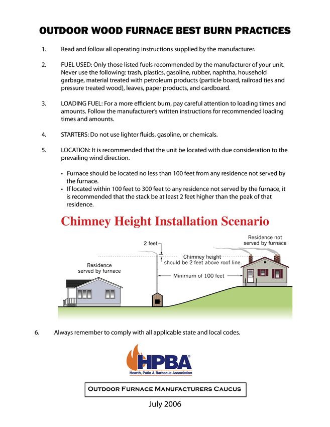
TABLE OF CONTENTS
HPBA Outdoor Wood Furnace Best Burn Practices      ………………………………		   3
HPBA Smoke Troubleshooting                         ………………………………		   4-7
Safety Instructions		         …………………………………………………………………		           8
Pre-Installation Tips         …………………………………………………………………		           9
Installation Guide		          …………………………………………………………………		           10 - 11
Making Water & Electrical Connections at the Stove ………………………………		   12
Piping Inside the Building …………………………………………………………………		              12
Wiring Inside the Building …………………………………………………………………		              13
Electrical Requirements       …………………………………………………………………		           13
Existing Hot Water Heat       …………………………………………………………………		           14
Wire Diagram for Gas Boiler …………………………………………………………………		             15
Domestic Hot Water            …………………………………………………………………		           16
Existing Forced Air           …………………………………………………………………		           16
Flat Plate Setup              …………………………………………………………………		           17
Water to Air Setup           …………………………………………………………………		            18
Electrical, Pressure, Temperature Coil Components  ………………………………		   19
Control Panel                 …………………………………………………………………		           20
Filling the Water Jacket      …………………………………………………………………		           20
Firing the Furnace            …………………………………………………………………		           20
Starting a Wood Fire          …………………………………………………………………		           21
Daily Fueling                 …………………………………………………………………		           21
Off Season Maintenance        …………………………………………………………………		           21
Maintenance                   …………………………………………………………………		           22
Wood as Fuel & Buying Wood                         ………………………………		   23
Wood–Fuel Comparisons                              ………………………………		   23
Safety & Starting during a Prolonged Power Failure ………………………………		   24
Ash Removal, Rotation & Disposal                   ………………………………		   25
Creosote Formation & Removal / Safety              ………………………………		   25
Runaway Chimney Fires                              ………………………………		   25
Troubleshooting               …………………………………………………………………		           26
Furnace Wiring Diagram        …………………………………………………………………		           28
Water Treatment               …………………………………………………………………		           29
Wood Burning Furnace Treatment                     ………………………………		   29 - 30
Maintenance Dosage              ………………………………………………………………		          30
System Testing                …………………………………………………………………		           30
EMERGENCY FIRST AID PROCEDURES                     ………………………………		   31
Warranty                      …………………………………………………………………		           32
Warranty Claim                …………………………………………………………………		           34
Conditional Work Order        …………………………………………………………………		           36
ETC Single Stage Electronic Temp Control           ………………………………		   38 - 39
HPBA Smoke Troubleshooting Checklist For Outdoor Furnaces

I. Installation Issues (Improper Smoke Dispersal)

  A. Chimney height relative to nearest downwind neighbor
		        1. If located 50 feet or less to any residence not served by the furnace, it is recommended that
  the stack be at least 2 feet higher than the eave line of that residence.
		        2. If located more than 50 feet but no more than 100 feet to any residence, it is recommended
		        that the stack be at least 75% of the height of the eave line of that residence, plus an
		        additional 2 feet.
		        3. If located more than 100 feet but no more than 150 feet to any residence, it is
		        recommended that the stack be at least 50% of the eave line of that residence, plus an
		        additional 2 feet.
		        4. If located more than 150 feet but no more than 200 feet to any residence, it is
		        recommended that the stack be at least 25% of the height of the eave line of that residence,
		        plus an additional 2 feet.
  B. Furnace located in sheltered area; insufficient wind to disperse smoke.
  C. Furnace sizing. Similar to other heating appliances, furnace should be properly sized based on the
  estimated heat loss of the served structure.

II. Fueling Issues

		 A. Burning less than optimal wood
			        1. Moisture content: Optimal moisture content should be between 20% and 30%
			        (seasoned wood)
			        2. Species: Hardwoods generally tend to burn cleaner than softwoods
			        3. Size: Larger pieces of wood tend to burn cleaner than smaller pieces
		 B. Burning less than optimal fuel loads
			        1. Loading: Firebox should be loaded based on outdoor temperature, anticipated heat
			        load requirements and the manufacturer’s instructions. Do not overload the chamber.
			        2. Charging intervals: Firebox should be charged regularly at the intervals specified
			        by the manufacturer’s instructions. Optimally, the firebox will be charged “hot,” i.e., the
			        fire will not go out between chargings.
		 C. Burning improper fuels
			        1. Only burn fuels approved by the manufacturer
			        2. Do not use volatile starters (such as lighter fuels, gasoline, chemicals) unless
			        approved by the manufacturer
			        3. Do not burn the following:
				                 a. Trash or household garbage
				                 b. Plastics
				                 c. Gasoline
				                 d. Rubber or tires
				                 e. Naphtha
				                 f. Material coated with petroleum products
				                 (e.g., particle board, railroad ties, pressure-treated wood)
				                 g. Leaves
				                 h. Paper products or cardboard

                                                                                                            4
III. Operational Issues

		 A. Improper combustion air – Natural Draft Units (No Blower):
			         1. Air inlet not restricted by debris (creosote, ash, etc.)
			         2. Flame baffle/flue not restricted by debris
			         3. Chimney not restricted by debris
			         4. Door seal in satisfactory condition (provides air-tight seal when door is shut)
			         5. Air inlet (damper or flapper) operates properly
			         (opens/shuts per manufacturer’s instructions, provides air-tight seal when shut)
			         6. Door seal in satisfactory condition (provides air-tight seal when door is shut)
		 B. Improper combustion air – Forced Draft Units (Blower):
			         1. Verify combustion blower operates in accordance with the manufacturer’s
		 instructions
				                  a. Blower starts and stops properly
				                  b. Combustion blower wheel spins properly
				                  c. Blower runs at proper speed – verify voltage to blower motor
			         2. Combustion blower tube not restricted by debris (creosote, ash, etc.)
			         3. Flame baffle/flue not restricted by debris
			         4. Chimney not restricted by debris
			         5. Air inlet (damper or flapper) for blower operates properly
			         (opens/shuts per manufacturer’s instructions, provides air-tight seal when shut)
			         6. Door seal in satisfactory condition (provides air-tight seal when door is shut)
		 C. Verify controls operate in accordance with the manufacturer’s instructions
			         1. Water temperature controls set properly
			         2. Draft controls set properly

IV. Maintenance Issues

        A. Verify that the furnace is being maintained in accordance with the manufacturer’s instructions.
Specifically, inspect:
		                1. Excessive ash buildup
			                       a. Grates blocked, restricting air flow
			                       b. Combustion fan blocked, restricting air flow
		                2. Excessive creosote buildup
			                       a. Combustion fan blocked, restricting air flow
			                       b. Flame baffle blocked, restricting air flow
			                       c. Chimney blocked, restricting air flow

V. Discussion

        Wood, like other fuels is made up of various amounts of carbon, hydrogen, and other elements. The burning of
wood is a chemical reaction that depends on many factors. The essential factors to complete wood burning are time,
temperature, and turbulence. Some other factors to take into consideration are: air intake; amount and placement,
density and moisture content of the fuel, size of the firebox compared to the size of the wood load, and adequate
room for the combustion process to take place.

         The smoke that is seen coming out of a chimney is essentially a combination of unburned fuel (carbon and
hydrogen) and moisture in the form of water vapor. The reason for the smoke is usually attributed to: (i) not enough
time for complete combustion, (ii) not enough mixing (turbulence) to complete the chemical process, (iii) not enough
temperature to get the fuel to that chemical conversion stage, or (iv) a combination of the above. In many cases,
excessive smoke can be reduced by adopting practices that improve complete combustion, reducing visible emissions
in the form of smoke.
                                                                                                                  5
A. Fuel
1. Moisture Content
Moisture content of the wood, either too high or too low, will affect the amount of visible smoke. Wood with
a low moisture content (less than 10%) will burn relatively quicker, resulting in some of the fuel going up the chimney
in the form of smoke, i.e., time was insufficient to complete the burn process. Wood with a moisture content too high
(more than 35%) can quench the flame causing smoke, i.e., temperature was insufficient to burn completely.
Wood moisture in the 20% to 30% range can be the best of both scenarios. It is dry enough to burn without
quenching the flame, yet the moisture is high enough to self-regulate the burn, giving it plenty of time to complete
combustion.
2. Density
The density of wood plays a part in the combustion process in the same way as moisture content. Softwoods
are by definition less dense and tend to burn more rapidly than hardwoods. Softwoods tend to create more smoke –
due generally to insufficient time to complete the burn. Denser hardwoods will burn more slowly and evenly, allowing
more time for the conversion of fuel to heat.
3. Size
The size of the wood can also be a factor in the amount of smoke produced. The surface area of a piece of
wood is one of the factors that will affect burn rate. Larger diameter logs tend to burn slower than smaller logs,
allowing for a more complete burn.
4. Improper Fuels
Burning materials not recommended by the manufacturer can play a major role in visible emissions. Materials
such as plastics, garbage, rubber tires, and even wood products such as cardboard and paper that may be coated with
petroleum products may emit excessive smoke. Fire starters such as gasoline, oil, and other chemicals can also make
an ordinary wood fuel load seem very dirty once burned. If people who own outdoor furnaces start fires with some
kindling and load with wood fuel as recommended above, they can eliminate a lot of the smoke that others see and
the problems that go with it.
5. Loading
The amount of wood loaded into an outdoor furnace in relation to the firebox size also has an effect on visible
emissions. For every size of wood load there is a minimum amount of space needed to complete the combustion
process. For instance, if a person were to load a relatively small firebox completely and load a larger firebox with the
same amount of wood, with all of the other factors being the same, the larger firebox would burn cleaner. In the
smaller firebox, the combustion process does not have enough room to expand, heat up, and mix before exiting the
firebox (insufficient time, temperature, and turbulence). Just because a firebox is large does not mean that it should be
filled completely. This large volume is used in part for what happens AFTER it is loaded.
B. Furnace Size
The size of a furnace should be large enough to provide sufficient heat without constant reloading. If the
target burn time is 12 hours, an adequately sized furnace will provide enough heat for 90% of all heating days. There
will always be the extraordinarily cold days for which no one can plan. A small furnace that needs constant reloading
will unavoidably be left unattended and will lose much of its available heat. In these situations, the firebox is left
relatively cold and restarting will be dirtier because of flame quenching on the cool firebox walls. A good rule to
follow, is that if the furnace cannot stay within 20% of it’s set point under regular reloading, then the unit is undersized
and a larger furnace is needed.
6C. Chimney Considerations
Although chimney height has little to do with overall emissions, it should be considered in ALL installations
of outdoor furnaces. Installers and dealers should first take a look at the proposed location and take a few things into
account. Location of nearby buildings, structures, and natural geography all affect the furnace’s ability to draft. While
higher is generally better, it is sometimes tough to convince the furnace owner to add length to the chimney because
of the extra cost.
VI. Conclusions
The proper use of an outdoor furnace can significantly reduce the visible emissions that it produces. Simple
fuel considerations with regard to moisture content, size, and amount help hinder the production of smoke and
ultimately help improve efficiency. Other obvious ways to help reduce smoke is to only burn fuels recommended by
the manufacturer and to not overload the furnace. In addition, the furnace size should be properly matched to the
heat load so that cold starts and overfilling are avoided. Chimney height should be in accordance with the state and
local codes, as well as surroundings, including neighbors. These areas, along with the “Best Burn Practices for Outdoor
Furnaces,” can greatly help in providing clean, safe heat from all outdoor wood burning furnaces.
7SAFETY INSTRUCTIONS
ALL INSTALLATIONS AND OPERATIONS MUST FOLLOW FEDERAL, PROVINCIAL, STATE, AND LOCAL CODES FOR
WIRING, PLUMBING, INSTALLING CHIMNEY. ALL WORK MUST BE PERFORMED BY QUALIFIED PERSONAL ONLY.
READ AND UNDERSTAND ALL PRECAUTIONS BEFORE OPERATING THE FURNACE.
ATTENTION!!! Save these instructions. Retain this manual as long as you own your Crown Royal Stove. Carefully read
and follow these directions.
DANGER!!! Do not start fire with chemicals, volatile fluids, rubber, plastics or garbage. Some processed wood contain
resins and should be avoided. Only competent persons with a sound understanding of this heating method should
operate this furnace. Improper firing could result in personal injury and/or damage to unit, and void warranty. Do not
burn garbage, gasoline, drain oil, naphtha, engine oil, railroad ties, particle board, leaves, cardboard, or any
other flammable liquids.
WARNING!!! Water Level
WARNING!!! Do Not open secondary combustion door while in operation, Doing so will result in fire hazard or severe
burns.
WARNING!!! All installations and operations of your furnace must follow STATE, PROVINCIAL and LOCAL LAWS pertaining
to operations, wiring, plumbing, and building codes. The installation must be performed by a qualified installer.
WARNING!!! Wood as the primary fuels in this unit.
WARNING!!! Only use wood with less then 30% moisture content.
WARNING!!! Do not install this unit on a combustible surface.
WARNING!!! All models operate at atmospheric pressure. DO NOT obstruct, block or plug the overflow vent tube in any
way, which is located on top of the furnace.
WARNING!!! This unit can not be hooked to a chimney already serving another appliance. When installing a chimney
that is higher than twelve feet, guide lines must be used.
WARNING!!! This unit must never be pressurized.
WARNING!!! Do not use an automatic stoker with this unit.
WARNING!!! Risk of Fire: Do not operate with fuel loading, heat exchanger door or secondary combustion door open.
Do not store fuel or other combustible materials within marked installation clearances. Inspect and clean flues and
chimney regularly.
CAUTION!!! Hot Surfaces: Keep children away. Do not touch during operation.
CAUTION!!! Do not start or operate furnace without checking heating fluid.
CAUTION!!! Check for buried cables and utility lines before digging trench.
CAUTION!!! For safety and proper temperature control, keep fuel door closed tightly during operation.
CAUTION!!! Do not fire up boiler until filled with water.
CAUTION!!! Do not to start the unit during a prolonged power failure.
CAUTION!!! Load fuel carefully to avoid injury to hands, fingers and other body parts that may come in contact with the
unit’s loading door opening.
CAUTION!!! Cleaning of the heat exchanger, flue pipe, and chimney is especially important at the end of the heating
season to minimize corrosion during the summer months caused by accumulated ash.
CAUTION!!! When installing the heat exchanger, be sure none of the existing system safety controls are disabled.
CAUTION!!! When installing heat exchangers do not tamper with existing controls. Wiring to existing blower can be
done with a line voltage or low voltage thermostat.
8PRE-INSTALLATION TIPS
ALL INSTALLATIONS AND OPERATIONS MUST FOLLOW FEDERAL, PROVINCIAL, STATE, AND LOCAL CODES FOR
WIRING, PLUMBING, INSTALLING CHIMNEY. ALL WORK MUST BE PERFORMED BY QUALIFIED PERSONAL ONLY.
Location
When choosing the location of your furnace you should consider prevailing wind direction, distance from home for
refueling and wood storage, and give consideration for any effect of your neighbors. Check with your homeowner’s
insurance company to ensure they will approve the location relative to the distance from building and combustibles.
We recommend a minimum of 20 feet from any building being heated with his unit.
Maintain all certification clearances as follows:
• Front of the fuel door 60” • Sides of the stove 36” • Back of the stove 60” • Chimney 60”
Determine how many buildings are to be heated with this unit; this will help with the calculations of distance to your
buildings that you are going to heat.
WARNING!!! Do not store fuel or other combustible materials within marked installation clearances.
Block or Pad Supports
Under normal conditions, four cement blocks are all that is required to support the furnace. Blocks should be at
least 24 inches wide, 24 inches long, 6 inches thick. Under very soft conditions a concrete pad may be needed, and
thickness should be no less that 4 inches.
Trenches
The trench must be 24 inches deep and 6 to 12 inches wide, it can be dug with a shovel or backhoe. Place all the dirt
to one side of the trench to allow room for working on the other side.
Chimneys
The size and height all depends on the unit you have purchased and where the unit will be located. If the furnace is
located within 300 feet of any residence, than the chimney stack must be at least two (2) feet higher than the peek of
the tallest roof. It is recommended that only a double insulated, stainless steel, 6” Class A chimney pipe to be used.
Contact your local dealer or Greentech Manufacturing, Inc for chimney purchase information.
9INSTALLATION GUIDE
ALL INSTALLATIONS AND OPERATIONS MUST FOLLOW FEDERAL, PROVINCIAL, STATE, AND LOCAL CODES FOR
WIRING, PLUMBING, INSTALLING CHIMNEY. ALL WORK MUST BE PERFORMED BY QUALIFIED PERSONAL ONLY.
CAUTION!!! Hot Surfaces: Keep children away. Do not touch during operation.
WARNING!!! Risk of Fire: Do not operate with fuel loading door, heat exchanger door or secondary combustion
door and / or ash removal doors open. Do not store fuel or other combustible materials within marked
installation clearances. Inspect and clean flues and chimney regularly.
WARNING!!! Do not install this unit on a combustible surface.
WARNING!!! This unit can not be hooked to a chimney already serving another appliance.
1. Inspect the ground conditions that you intend to install your furnace on. If the area is unstable or has a history
of staying wet, you may have to improve the soil with gravel as well as raising the elevation. A cement pad of 4” - 6”
inches should then be used. The furnace in most cases can be placed on four cement blocks and they should not be less
than 24 inches wide, 24 inches long, 6 inches thick. Obtain the footprint of the model of furnace you have purchased.
Place your blocks so that the legs will be in the center of them. For a pad, the width need not be greater that the outside
width of furnace. The length of pad should be as long as the outside length dimension and an added length is desirable
as a work area at the loading door. A four-foot extension is most commonly used.
DANGER!!! Do not start fire with chemicals, volatile fluids, rubber, plastics or garbage. Some processed wood
contain resins and should be avoided. Only competent persons with a sound understanding of this heating
method should operate this furnace. Improper firing could result in personal injury and/or damage to unit, and
void warranty. Do not burn garbage, gasoline, drain oil, naphtha, engine oil, railroad ties, particle board,
leaves, cardboard, or any other flammable liquids.
2. Select a tubing product of at least one inch inside dimension, which is rated at 180 degrees F 100 PSI continuous
flow. Plan to have no joints, couplings, unions, etc. joining the tube between the building being heated and the stove.
The chance for a leak is too great. The pipe should have a construction of polyethylene and an oxygen barrier. Also,
mark your feed and return lines prior to covering and allow enough pipe above ground at both ends for a relaxed
connection.
3. The supply and return tubing needs to be insulated to prevent heat loss. It is recommended that at least ½” of
insulating material be used. Both the return and supply pipes can be insulated together so that the temperature drop
is minimized.
4. All wiring must conform to local codes. Use an electrical wire rated and approved for underground installations.
This wiring can be placed in the same trench below the water lines. Use 12-2 UF wire with ground to provide power
to the draft inducer blower, aqua stat, night light, etc. at the stove. This is satisfactory for most applications but a state
certified electrician must be consulted.
105. There are some products that incorporate the supply and return pipe, insulation, and moisture shield into one
product. This is fine, but do not select solid black drain tile, it will eventually crack causing moisture to seep through the
insulated pipe and heat loss into the ground. The critical issue is to keep the insulated pipes from coming into contact
with the soil, ground water, etc. We recommend using Insul-Seal, which is available in 3” and 4”. This product is water
tight and resists heat loss.
6. The trench must be 24” deep and 8” - 12” wide. If possible have a gradual slope in your trench to allow drainage
away from lines and out of the trench bottom. Place electrical supply in bottom of trench and cover with 6” of gravel or
dirt. At this point a water barrier is required. Several methods are possible, but the most important factor is; if ground
water comes in contact with your heating lines, it will be the greatest heat loss to your system. A minimum of R10
insulation value is recommended, and a water-tight vapor barrier such as a continuous poly tube of plastic PVC pipe to
encase your insulation is a must. NOTE: If you need to bury lines under an area where vehicles will cross, you should
increase the depth of trench to three feet or place planks over the trench in that area to spread the load and reduce the
pressure generated on the lines.
7. The supply and return tubing and the power wire can be lowered in the trench, brought through the buildings
being heated, and extended a minimum of 36” out of the soil where the stove is to be placed. Seal the openings around
the tubing where it enters the building and seal the tubing where it extends out of the ground at the location where the
stove is to be placed.
8. Connections to the furnace are clearly marked. The installation of isolation valves at both ends of the pump is
recommended as well as a valve at the return line. This will allow you to shut off water supply for repair or if additional
heating components are added to the system. It is recommended that piping used is able to withstand 100 PSI at
180 F, and is at least 1” (inch) in diameter. 1 1/4 “ (Inch) piping is recommended for larger systems. A single junction box
at the rear of the furnace is included for your power supply, and should be connected by a qualified person.
9. A hole large enough to accommodate two lines and insulation is required and attention to sealing this point of
entry is very important. Be sure to bring pipes, insulation and vapor barrier completely through wall and seal from both
sides.
10. You will require either water-to-water (tube and shell or plate) or water-to-air exchanger (rad) to transfer or
extract heat energy from the hot water your furnace has produced. Your local authorized dealer or certified plumber
can design and install a system to best suit your requirements.
11. The Class A stainless steel chimney pipe comes in various lengths, spanning from eighteen (18) inches to forty
eight (48) inches. Install each section of piping by placing male and female sections together then twisting them to lock
sections together. When installing your chimney piping, it is recommended by the chimney manufacture that it must be
laterally braced every eight (8) feet. It is also recommended by the chimney manufacture that the height of the piping
does not exceed a total of forty (40) feet.
If additional height is needed, contact your local dealer or Greentech Manufacturing Inc.
CAUTION!!! Hot Surfaces: Keep children away. Do not touch during operation.
WARNING!!! Risk of Fire: Do not operate with fuel loading door, heat exchanger door or secondary combustion
door and / or ash removal doors open. Do not store fuel or other combustible materials within marked
installation clearances. Inspect and clean flues and chimney regularly.
WARNING!!! Do not install this unit on a combustible surface.
WARNING!!! This unit can not be hooked to a chimney already serving another appliance.
11MAKING WATER AND ELECTRICAL CONNECTIONS AT THE STOVE
ALL INSTALLATIONS AND OPERATIONS MUST FOLLOW FEDERAL, PROVINCIAL, STATE, AND LOCAL CODES FOR
WIRING, PLUMBING, INSTALLING CHIMNEY. ALL WORK MUST BE PERFORMED BY QUALIFIED PERSONAL ONLY.
1. After the stove has been placed on the concrete or pads, open rear access door at the back of the stove.
2. The return (cold water) pipe must be connected to the fitting at the upper position and the supply (hot water)
at the fitting toward the bottom of the stove. If multi-pole locations are to be heated, tees must be added
on both the supply (hot) and return (cold). It is necessary to use brass fittings between the stainless and
other metals.
3. The stove has been pre-wired at the factory; therefore it is only necessary to connect the common from the wire
from the trench to the common from the stove, neutral to neutral, ground to ground. Ensure that the
connections are water tight. Connections are located on the inside of the air box.
4. Re-install insulation ensuring the blower has sufficient airspace & close the rear access door.
PIPING INSIDE THE BUILDING
ALL INSTALLATIONS AND OPERATIONS MUST FOLLOW FEDERAL, PROVINCIAL, STATE, AND LOCAL CODES FOR
WIRING, PLUMBING, INSTALLING CHIMNEY. ALL WORK MUST BE PERFORMED BY QUALIFIED PERSONAL ONLY.
It is recommended that piping used is able to withstand 100 PSI at 180 F, and is at least 1” (inch) in diameter.
1 1/4 “ (Inch) piping is recommended for larger systems.
1. For each building, a circulation pump is needed. The pump can be located on the supply side (hot water).
2. Before each pump, a filtering device must be installed. This filter will minimize the contaminants in the water
and maximize the life of the circulation pump.
3. If the central heating system in the building is a forced air furnace, it is important to select the appropriate water
to air exchanger. Contact your heating contractor for proper size. The coil is to be installed in the furnace
plenum. If there is an air conditioning evaporator coil in the plenum, install the water to air coil after the
a/c coil.
4. If the central heating system is a hot water boiler system, a water to water heat exchanger is needed.
The water from an open system will contaminate the closed system if the waters are mixed together.
5. It is advisable to install ball valves, isolation flanges, etc. to make the removal and the replacement components
easier.
12WIRING INSIDE THE BUILDING
ALL INSTALLATIONS AND OPERATIONS MUST FOLLOW FEDERAL, PROVINCIAL, STATE, AND LOCAL CODES FOR
WIRING, PLUMBING, INSTALLING CHIMNEY. ALL WORK MUST BE PERFORMED BY QUALIFIED PERSONAL ONLY.
1. The electrical wiring must be done by an experienced HVAC technician to ensure the system will operate
as desired and is safe.
2. It is recommended that the circulation pump or pumps run continuously.
3. The existing forced air circulation blower needs to be wired through the circuit board to a 24 volt wall thermostat
which is dedicated for this purpose. The other wall thermostat which is for the forced air (Oil, LP, NG or Electric)
is left intact. The new 24 volt wall thermostat will cause the circulation blower to run without the burners
coming on. An experienced HVAC technician needs to perform the wiring.
4. The electrical for a boiler system is more complicated because the existing boiler wall thermostat is used but the
burners on the (Oil, LP, NG or Electric) boiler are not to operate when the water from the water stove is to provide
heat. It is necessary to have an experienced HVAC technician wire this configuration.
5. If air conditioning is used you must add a relay DPDT to prevent the condenser from turning on when the
fan is energized.
ELECTRICAL REQUIREMENTS
ALL INSTALLATIONS AND OPERATIONS MUST FOLLOW FEDERAL, PROVINCIAL, STATE, AND LOCAL CODES FOR
WIRING, PLUMBING, INSTALLING CHIMNEY. ALL WORK MUST BE PERFORMED BY QUALIFIED PERSONAL ONLY.
Electrical Rating: 120 AV Volts, 6 AMPS, 60 Hz. Wire must be rated and approved for direct burial if it is to be buried in
the same trench as the water lines. Boiler power connection box is located at rear of boiler inside back cover. Minimum
supply 15 AMPS. Maximum device 15 AMPS. USE COPPER CONDUCTORS ONLY.
13EXISTING HOT WATER HEAT
ALL INSTALLATIONS AND OPERATIONS MUST FOLLOW FEDERAL, PROVINCIAL, STATE, AND LOCAL CODES FOR
WIRING, PLUMBING, INSTALLING CHIMNEY. ALL WORK MUST BE PERFORMED BY QUALIFIED PERSONAL ONLY.
It is recommended that piping used is able to withstand 100 PSI at 180 F, and is at least 1” (inch) in diameter.
1 1/4 “ (Inch) piping is recommended for larger systems.
The Crown Royal Stove shall be installed without interfering with the normal delivery of heated water from the
original boiler.
The Crown Royal Stove shall be installed without affecting the operation of the electrical and mechanical safety
controls of the original boiler.
The Crown Royal Stove shall provide a changeover from one fuel to the other without requiring manual adjustment of
any controls or components other than the thermostats.
The Crown Royal Stove shall have provisions for preventing, or adequate water capacity within the boiler to prevent
damage from loss of circulation due to electrical power failure.
The Crown Royal Stove shall be installed without changing the function of the controls or rewiring the original boiler.
A wiring interconnection is permitted. The electrical system of both boilers shall be powered from a single branch
circuit without exception.
FOR UNITS USED IN CANADA THE FOLLOWING IS RECOMMENDED:
1: Operate the existing boiler periodically to ensure that it will operate satisfactorily when needed.
2: Do not relocate or bypass and of the safety controls in the existing boiler installation.
3: The operation of the existing gas boiler must be verified for acceptable operation before and after installation of the
Crown Royal Stove by a gas fitter who is recognized by the regulatory authority.
4: Do not connect to any chimney or vent serving a gas appliance.
5: Ensure the installation complies with the requirements of CAN/CSA-B365. Any changes to the installation should
comply with CSA B139 (for oil-fire), C22.1 (for electric), or CAN/CGA-B149.1 or CAN/CGA-B149.2 (for gas-fired).
14WIRING DIAGRAM FOR GAS BOILER
Put ‘strap on Aquastat’ on the supply side of the water-line from outdoor wood furnace. Run thermostat wire from the
‘strap on Aquastat’ to R and G of fan control center. Run 115V power to white and black wire of fan center coil. Break one
wire of gas boiler Aquastat. Hook one side of wire to brown wire of fan control center contact. Hook other side of gas
boiler Aquastat wire to black on fan control center contact. Set ‘strap on Aquastat’ to close at 100-120 degree.
15ALL INSTALLATIONS AND OPERATIONS MUST FOLLOW FEDERAL, PROVINCIAL, STATE, AND LOCAL CODES FOR
WIRING, PLUMBING, INSTALLING CHIMNEY. ALL WORK MUST BE PERFORMED BY QUALIFIED PERSONAL ONLY.
DOMESTIC HOT WATER
The Domestic Hot Water Flatplate Kit consists of a Water to Water Heat Transfer unit and the fittings needed to hook it
up. The unit goes on top of the domestic hot water heater and is connected as shown below.
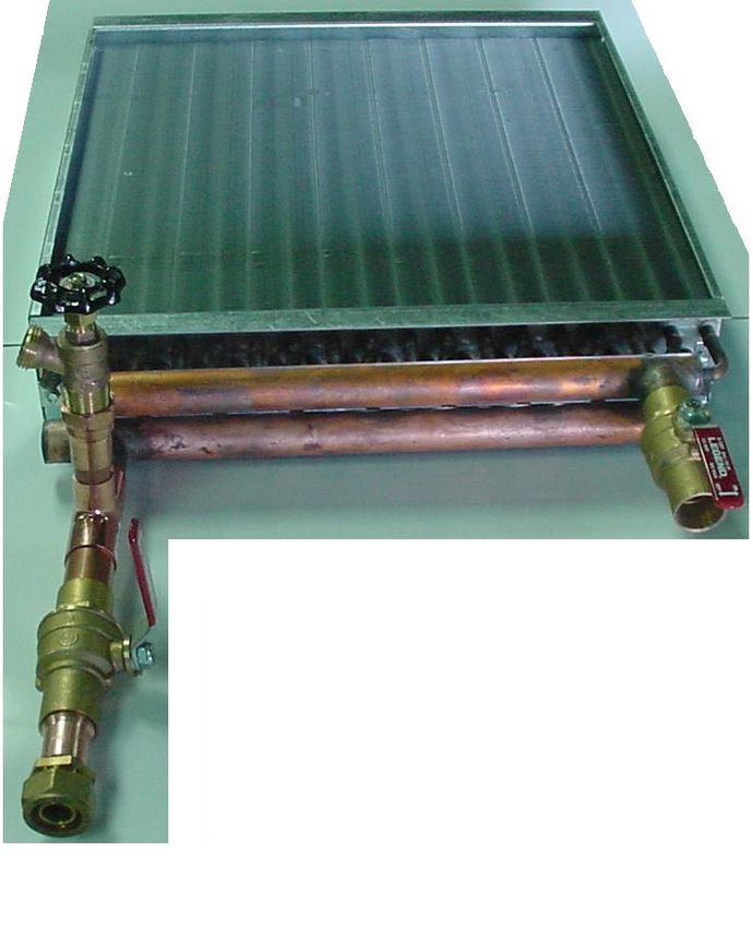
EXISTING FORCED AIR
A water to air heat exchanger is inserted in the existing plenum. In most cases the heat exchanger is placed in a
horizontal position, keeping all four sides level. The air must be forced through the finned area of the heat exchanger
evenly. The hot water line coming from the hot - water tube enters the bottom fitting of the heat exchanger and exits
the top fitting, which returns to the furnace. If the plenum is too large or too small, it must be altered to fit the heat
exchanger properly.
After installation of the add-on water to air exchanger, the air flow must be increased to fuel the furnaces, electric
furnaces, and electric/gas furnaces. Methods of doing this are:
BELT DRIVE SYSTEM: Blower pulleys and motor pulleys may be changed but the electric current flowing through
the motor shall not exceed the nameplate rating. (A blower motor or larger power may be used.)
DIRECT DRIVE SYSTEM: The motor shall not be changed, however the speed of the motor may be increased.
Water return to
Crown Royal Stove
Hot Water from
Crown Royal Stove
THE HEAT EXCHANGER: Air blows through the heat exchanger’s grill taking the heat from the water heated grill and
blowing it into your existing ductwork.
CAUTION!!! When installing heat exchangers do not tamper with existing controls. Wiring to existing blower can
be done with a line voltage or low voltage thermostat.
NOTE: Wire thermostats according to directions provided by the manufacturer.
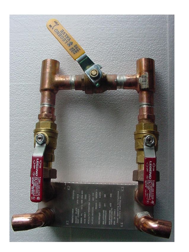
16FLAT PLATE SETUP
If using 1” tubing, open ball valve 1/3.
If using ¾” tubing, close valve.
Wood Stove Inlet Wood Stove Outlet
(water line from wood stove) (Connect to gas furnace
or boiler exchanger)
Ball Valve 101-024 101-024 Ball Valve
Hot Water Outlet Hot Water Inlet
(domestic to faucets) (hot side of water heater)
The Flat Plate Heater can be installed on either the cold side or the hot side of the hot water heater. If installed on the
cold side, the hot water heater needs to be left on to maintain the temperature in the hot water heater. If installed on
the hot side, the hot water heater needs to be turned off and the hot water heater is now a reservoir.
17WATER TO AIR SETUP
Water to Air Exchanger
Boiler Drain
Ball Valve 101-024
Kitec Fitting
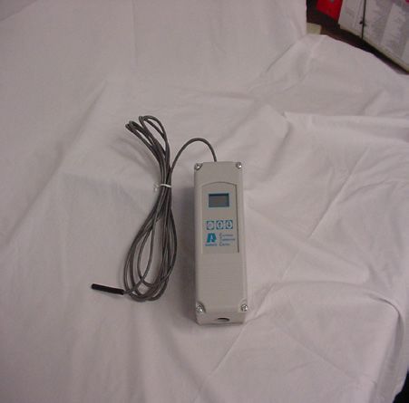
18ELECTRICAL, PRESSURE, TEMPERATURE COIL COMPONENTS
Aqua Stat Aqua Stat Well Limit Switch Blower Fan
THE CONTROL PANEL
The control panel is to be kept shut when fueling the fire box and at all other times except when using the controls.
The aqua stat powers the inducer draft blower to maintain the desired water temperature. The aqua stat is set at 150
degrees F at the factory, which means the inducer will run until the water in the jacket reaches 150 degrees F. As the
outside air temperature drops as the season progresses into the winter the setting can be raised to a high of 180 degrees
F. The reason the aqua stat is set lower is that it is not necessary to have the high temperature in the fall and spring.
Therefore, the stand by heat lost is reduced.
The limit switch is a normally closed circuit, but when the water temperature reaches 190 degrees F the circuit opens
thereby shutting the inducer off. The limit is to prevent the water from over heating.
The on and off switch is to shut the power off to the inducer blower when the fire box is being filled.
The temperature gauge is for information purposes. If the water temperature reaches 200 or above, make sure the
inducer is off, the doors are shut tightly, the circulation pump is on and the furnace (forced air) in the building (house)
has its circulation blower on to take the heat away from the exchanger and if the system in the building (house) is
hydronic (boiler) has its pump circulating the water throughout the zones.
CONTROLLER: This unit controls the water temperature inside the water jacket. It is factory set to cut-in at 150
degrees and cut-out at 180 degrees. When cut-in occurs the fan will run until the temperature reaches 180 degrees
then the fan will turn off. Only qualified personal should adjust the temperature control. For hooking into the hot water
heating systems your settings should be 170 to 190 degrees.
HI-LIMIT: This unit will turn off the boiler fan if the water temperature exceeds the 190 degree preset temperature.
Beware that this control will automatically start if ‘hi-temp’ is corrected.
FAN / LIGHT SWITCH: The fan switch controls the fan. The light switch controls the light. Turn off the fan when loading
& turn in on after closing firebox door.
19FILLING THE WATER JACKET
Your outdoor furnace has a vent pipe that protrudes through the roof and is in front the chimney. By placing a garden
hose in this pipe you can fill your furnace to the proper water level. Because this furnace is an open-to-atmosphere
system, it is normal that water will have to be added annually. Depending on circumstances, 5 or 10 gallons is not
unusual. To make this procedure more convenient, a boiler drain valve (tap, faucet) can be installed into the return
furnace line allowing you to connect a double female (automatic washing machine hose) between it and your domestic
supply line.
On your initial filling of your furnace make sure to inspect all connections in your system for leaks. In your system a
bleeder valve should have been installed at the highest point. This will allow you to remove any air from the system.
CAUTION, do not fire furnace until it is filled with water.
Allow furnace to run for two days and check water levels and fittings for leaks. If all is okay, you now should add the
manufacturer’s recommended water treatment.
FIRING THE FURNACE
Storage of your solid fuel must be in a debris free, dry environment that is at least sixty (60) inches from the front of the
stove and sixty (60) inches from the sides or back of the stove.
On starting an initial fire the use of less coarse wood and paper is required. Add heavier fuel gradually until a suitable
fire is achieved. The furnace will continue to feed an air supply to the fire until your aqua-stat shut off temperature is
reached (180F). On this initial start up the water jacket will reach what is called the dew point. This creates sweat inside
the fire box which may last a couple of days and is normal. Condensation will come out of all doors until the unit reaches
operation temperature. Heating of the water will also cause it to come out of the fill pipe. All are normal occurrences.
Although everyone has different methods of firing. Filling your furnace to capacity reduces the efficiency of the furnace.
It is better to load twice a day with less wood than once a day filling to capacity. Smaller fuel loads burn hotter, cleaner
and more thoroughly. By burning off more of the gases (smoke), which is wood broken down, you enhance the over all
efficiency of your system by reducing creosote and increasing heat transfer to the water.
This furnace will not burn poor quality wood (green, rotten), but for best results and efficiency use proper
seasoned (20% -30% moisture content). Cutting and storing wood one season ahead is recommended.
Do not fill the unit higher than as stated below.
RS 7400E : 24” (inches) from the bottom of the ceramics.
20STARTING A WOOD FIRE
1. Open the control panel door and turn the inducer switch off and then close the control panel door.
2. Open the fuel door and insert crumpled paper. Pile a few pieces of dry kindling on the paper.
Do not use chemicals or fluids to start the fire.
3. When the kindling wood is well ignited, add larger pieces of wood. (Small amount)
4. Shut the fuel door.
5. Open the control panel to turn the inducer on, then close the panel door.
6. Keep adding small pieces of wood, until a bead of coal is established. Then fill stove with wood (20%-30%
moisture content).
7. When firing the stove the first time in the season, the water jacket will sweat as the fire warms the cold water.
This could last for 48 hours and does not indicate the stove is leaking water.
Do not fill the unit higher than as stated below.
RS 7400E : 24” (inches) from the bottom of the ceramics.
DAILY FUELING & FIRING ROUTINE
Prior to opening the fuel door, open the control panel, turn the inducer fan switch off. Open the fuel door slowly and
stand behind the door so that the door is between you and the fire box. Do not rake coals into secondary burn chamber.
Do not load the fire box more than seventy five percent (75%) with wood. If additional fuel is added you will not
maintain a hot enough burn and your efficiently rate will deteriorate. Only add enough wood to provide heat until the
next fueling time. Overfilling the fire box will cause the fire to smolder, create excessive creosote and result in more fuel
being consumed.
OFF SEASON MAINTENANCE
CONTACT YOUR LOCAL DEALER FOR ANY QUESTIONS REGARDING MAINTENANCE.
At the end of the heating season, shut off the pump, empty the fire box of all wood and ash, remove the creosote and
clean the chimney. Remove and clean the inducer blower, clean the secondary burn chamber area, check the door
gaskets and replace as necessary.
Refill to the top, treat the water, turn on the circulation pump for at least four hours to mix the treatment thoroughly,
check for leaks and then shut the pump off. See page 30 for water treatment information.
Care for the exterior of your furnace is minimal. The unit may be washed using water and a mild non-abrasive cleaner
suitable for painted surfaces. Avoid direct water pressure to electrical components and connections.
CAUTION!!! Make certain that all electrical power to the furnace and components are shut off before washing.
21MAINTENANCE
CONTACT YOUR LOCAL DEALER FOR ANY QUESTIONS REGARDING MAINTENANCE.
The # 1 Rule for long life of your furnace is Proper PH Level, maintain between 8-10. Yes, even high grade stainless steel
can corrode in the right acidic conditions. Contact your local dealer for PH test paper.
It is recommended to have a rain cap so that moisture doesn’t come in contact with the ashes in the firebox, which is
highly corrosive.
The furnace will require cleaning frequently due to the accumulation of soot, creosote, and ash.
Check weekly for creosote build-up until experience shows how often cleaning is necessary.
Be aware that the hotter the fire and dryer the wood, the less creosote is deposited. Have a clear understanding how to
handle a fire.
Daily Note: Fan must be shut down in order to fill up and clean the stove.
• Check water level and add as necessary.
• Check for adequate fuel supply.
• Check if temperature setting corresponds to thermometer.
• Check for ash buildup in firebox and clean as necessary (Use a metal container to empty ashes into.)
Weekly
• Check air bypass tubes and chimney, remove any creosote, soot or ash build-up that may have occurred.
• Check fan and solenoid to ensure proper air velocity is happening at ejection points.
• Remove collected ash from secondary burn chamber.
• Use brush provided to remove buildup from vertical & horizontal heat exchanger tubs.
Monthly
• Check the water fill pipe, add water till excess flows over the top.
• Check PH level of the water and add rust inhibitor as required.
• Check airbox for air leaks.
Annually
• Lubricate solenoid shaft.
• Check fan and solenoid to ensure proper air velocity is happening at ejection points.
• Check the door gasket and replace if needed.
• Clean out any ash buildup from back.
• Check heat exchanger tubes and chimney, remove any creosote, soot or ash build-up that may have occurred.
• At the end of the season, thoroughly clean out all the ashes in the firebox and chimney.
Place a chimney cap on the chimney in order to keep rain from entering the firebox.
Remember : Your preventive maintenance program will give you years of trouble free service.
22WOOD AS FUEL
Wood can be classified as softwood or hardwood. The pines, spruces and firs are common softwoods and the oaks,
elms, birches, and maples are the common hardwoods. Softwoods burn rapidly and are more resinous than the
hardwoods, therefore they will cause a greater creosote build-up. Hardwoods produce a long lasting fire with uniform
heat. Hardwoods are the most desirable and are used by the majority of wood burners. Note: Only burn wood with a
moisture content of 30% or less.
Establish a proper place for; the storage of fuel, (This area should be elevated off the ground and allow the fuel to be
dry at all times.) care of the appliance, and proper firing techniques. Check daily for creosote build-up until experience
shows how often cleaning is necessary. Be aware that the hotter the fire, the less creosote is deposited, a weekly cleaning
may be necessary in warmer weather, while a monthly cleaning may be adequate in the coldest months. Have a clearly
understood plan of how to handle a chimney fire. See (RUNAWAY CHIMNEY FIRE)
BUYING WOOD
A cord of wood is a ranked stack of logs 4’ x 4’ x 8’. Usually when you purchase firewood, it is sold by the “face cord”.
A face cord is ranked stack of logs 4 feet high, 16 inches deep and 8 feet long. Wood is sometimes sold by the ton.
A ton of dry hardwood is equivalent to approximately ½ full cord. Whenever possible it is best to burn hardwood that
has been split and air dried for one year.
WOOD-FUEL OIL COMPARISONS
(Approximations)
BTU’S Per Cord Equivalent Value Gals.
Dried Wood Type of Wood #2 Fuel Oil
17,000,000 White Pine 120
18,000,000 Spruce 130
24,000,000 Soft Maple 170
27,000,000 Red Oak 195
29,000,000 Hard Maple 200
30,500,000 Hickory 215
23SAFETY
Whenever the loading door is to be opened, it should always be cracked slightly to allow oxygen to enter and burn off
any combustion gases that are present before fully opening. Failure to do this could result in sudden ignition of the
unburned gases when the door is opened.
A stove should never be filled with wood so that the flue gas exit is blocked or impeded in any way. Burning wood
generates carbon monoxide and if the flue gas exit is blocked the carbon monoxide can be forced into the area the
stove is heating and have fatal consequences.
Do not fill the unit higher than as stated below.
RS 7400E : 24” (inches) from the bottom of the ceramics.
STARTING DURING A PROLONGED POWER FAILURE
CAUTION!!! Do not to start the unit during a prolonged power failure.
During a prolonged power failure, where no power is being sent to the furnace, do not load with new fuel or try to start
a new fire. It is recommended that you contact your local dealer or Greentech Manufacturing Inc, Inc to find out what
size of generator is needed to keep your furnace running. Once an approved generator is connected to the stove, the
unit may be started normally.
24ASH REMOVAL, ROTATION & DISPOSAL
CAUTION! Ashes should never be allowed to come into contact with the vertical heat exchanger tubes. With an
excessive ash buildup, primary combustion air is restricted and the unit’s output will be reduced.
Ash removal should be done weekly to maintain a good ash rotation. Remove ashes
when the furnace is low on wood. Place ashes into a metal container with a metal lid.
This closed metal container of ashes should be placed on a noncombustible floor or on the ground, well away from all
combustible materials until final disposal. Ashes should remain in the closed container until all cinders have cooled,
in an area that is at least sixty (60) inches from the front of the stove and sixty (60) inches from the sides or back of the
stove.
CAUTION: Hot coals can last for days. Disposing of them improperly or to soon can cause a fire.
WARNING!!! RISK OF FIRE
With the exception of the start-up and ash removal periods, all doors should never be left open. This unit should never
be left unattended with any of the doors left open.
CAUTION: Always close all doors or serious overheating will occur and damage the unit.
CREOSOTE FORMATION & REMOVAL
When wood is burned, organic vapors and tar combine with expelled moisture forming creosote, which clings to the
interiors of the stove. Creosote vapors condense in the relatively cool chimney of a slow burning fire, as a result creosote
accumulates on the flue lining. When creosote ignites it creates an extremely hot fire and can cause damage to the
stove and / or persons. The chimney and its connectors should be inspected at least twice a month, during the heating
season, to determine if a buildup is occurring. If creosote has accumulated it should be removed to reduce the risk of a
chimney fire.
RUNAWAY CHIMNEY FIRE
To avoid a chimney fire, ensure that daily, weekly, month and annual maintenance techniques are being followed.
If a fire is to occur shut down the power to the unit, and ensure all doors are securely shut. This will eliminate new
oxygen from being introduced into the firing chamber, thus snuffing both the chamber and chimney fires.
25TROUBLESHOOTING
If the furnace fails to heat up:
1. Check fire.
2. Check fan for operation.
3. Check that solenoid damper is open to allow air velocity.
4. Check water level of furnace.
5. Check for creosote blockage at chimney and vertical & horizontal heat exchanger tubes.
6. Check temperature setting.
7. Check for power at furnace.
8. Check that moisture content of the wood is less then 30%.
If furnace water is hot, but buildings do not have heat:
1. Check pumps and check for closed valves.
2. Check filter or Y-Strainer for flow blockage.
3. Check for air in system at exchanger by bleeding off.
If furnace boils:
1. Check that all door are closing properly and that door gaskets are completely sealed.
3. Check that the solenoid damper plate is opening and closing without hang-ups.
5. Check that the temperature settings are correct and water levels.
4. Check that airbox is completely sealed at the back of the stove.
If furnace has shut down:
1. Check to ensure that the unit has power (does the outside light work).
2. Check the water temperature (furnace has a high temperature cut-out of 190 degrees F.).
3. If all the checks have not corrected the problem, have a qualified technician check the control panel.
2627
28
Water Treatment                     Effective January 1, 2007
Greentech Manufactruing Inc. requires our recommended – WOOD BURNING FURNACE TREATMENT be added to the
water in the furnace. Premature corrosion in a hot water wood furnace is a result of not treating the water with the
correct corrosion resistant inhibitor or with the wrong dosage.

Instructions for the proper start-up mixture and for the yearly additional amount to maintain proper treatment-to-
water balance are on the container label and on an attached document.

Upon installation of the furnace:
       • Add the recommended dose of treatment to the water when filling the furnace
       • Retrieve a sample of the treated water in to the provided container
       • Provide the information requested on the container label provided by the dealer/distributor
       • The sample is to be sent with the completed furnace registration form
       • Return this package to your dealer/distributor for analysis and warranty registration
       • Water sample to be analyzed by authorized personnel
       • If the water sample is not suitable, an additional treatment will be recommended

NOTE: This sample needs to be of the water that is in your furnace AFTER THE TREATMENT HAS BEEN ADDED TO IT.
The sample is to be sent to the address provided on the sample container label.

                                  Wood Burning Furnace Treatment
READ THE ENTIRE LABEL BEFORE USING THIS PRODUCT.

Specifically designed to treat water that is contained in a closed-loop,
heated by wood fired furnaces that provide heat to buildings.

        • Helps protect the system from scale, sludge, and corrosion
        • Vapors help prevent corrosion throughout the furnace
        • Economical - one gallon/3.78 liters treats 300 gallons/1134 liters of system capacity

DIRECTIONS FOR USE

NOTE
1. KEEP CONTAINER CLOSED WHEN NOT IN USE
2. DO NOT MIX WITH ANY OTHER CHEMICALS

INITIAL DOSAGE

1. Consult the owner’s manual or contact the manufacturer to determine the water volume of the furnace.
Furnace Water Capacities in US Gallons:
RS 7400E contains 390 gallons.

2. Determine the entire volume of water to be treated by adding the water volume of the furnace with the estimated
volume of water contained in all of the piping of the system*.

3. Before adding product, add water until the system is 1/4 full.

4. Add 1 to 1.5 gallon(s)/3.78 to 5.67 liters for each 300 gallons/1134 liters of system water volume.
Do not exceed 2 gallons/7.56 liters per 300 gallons/1134 liters volume

5. Add water until the system is full. To avoid collecting a heated sample, circulate the water for at least 24 hours
                                                                                                                        29
You can also read