Installation manual Terra AC - Copyright ABB. All rights reserved
←
→
Page content transcription
If your browser does not render page correctly, please read the page content below
Installation manual
Terra AC

© Copyright ABB. All rights reserved
Copyright

All rights to copyrights, registered trademarks, and trademarks reside with their respective
owners.
Copyright ® ABB EV Infrastructure. All rights reserved.

2                                                                        BCM.V3Y01.0-EN | 002
Contents

Contents

1       About this document.......................................................................... 7
        1.1       Function of this document...................................................................................................... 7
        1.2       Target group...............................................................................................................................7
        1.3       Revision history.......................................................................................................................... 7
        1.4       Language..................................................................................................................................... 7
        1.5       Illustrations................................................................................................................................. 7
        1.6       Units of measurement.............................................................................................................. 7
        1.7       Typographical conventions......................................................................................................7
        1.8       How to use this document.......................................................................................................7
        1.9       General symbols and signal words........................................................................................ 8
        1.10      Special symbols for warnings and dangers......................................................................... 9
        1.11      Related documents................................................................................................................... 9
        1.12      Manufacturer and contact data............................................................................................10
        1.13      Abbreviations........................................................................................................................... 10
        1.14      Terminology..............................................................................................................................10
        1.15      Orientation agreements......................................................................................................... 11

2       Description......................................................................................... 12
        2.1       Short description..................................................................................................................... 12
        2.2       Intended use............................................................................................................................. 12
        2.3       Product label (IEC portfolio).................................................................................................. 12
        2.4       Product label (UL portfolio)................................................................................................... 13
        2.5       Working principle.....................................................................................................................14
        2.6       Overview.................................................................................................................................... 15
                  2.6.1    Overview of the system..........................................................................................15
                  2.6.2    Overview of the EVSE, outside..............................................................................15
                  2.6.3    Overview of the EVSE, inside (CE model)........................................................... 17
                  2.6.4    Overview of the EVSE, inside (MID model)......................................................... 18
                  2.6.5    Overview of the EVSE, inside (UL model)........................................................... 19
                  2.6.6    Overview of the EVSE, inside (UL model with display)....................................20
        2.7       Options...................................................................................................................................... 21
                  2.7.1    Display....................................................................................................................... 21
                  2.7.2    EV charge cable, Type 2.......................................................................................... 21
                  2.7.3    Socket, Type 2.......................................................................................................... 21
                  2.7.4    EV charge cable, Type 1 (UL portfolio)................................................................ 22
                  2.7.5    4G Communication................................................................................................. 22
                  2.7.6    Load management ................................................................................................. 22
        2.8       Control elements..................................................................................................................... 23
                  2.8.1    LED indicators..........................................................................................................23
        2.9       TerraConfig app to do the commissioning .......................................................................24

BCM.V3Y01.0-EN | 002                                                                                                                                           3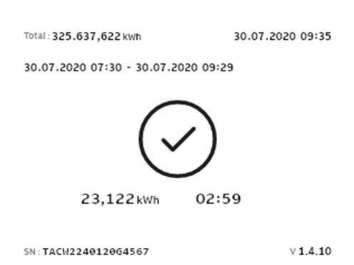
Contents

           2.10      Description of the display screens (option)...................................................................... 24
                     2.10.1   Boot screen.............................................................................................................. 24
                     2.10.2   Standby/Idle screen............................................................................................... 25
                     2.10.3   Authorization screen.............................................................................................. 25
                     2.10.4 Preparing to charge screen...................................................................................26
                     2.10.5   Charging screen...................................................................................................... 26
                     2.10.6   Charging completed screen.................................................................................. 27
                     2.10.7   Fault detected display messages........................................................................ 27

3          Safety.................................................................................................. 29
           3.1       Liability...................................................................................................................................... 29
           3.2       Required qualifications for the installation engineer...................................................... 29
           3.3       Personal protective equipment............................................................................................ 29
           3.4       FCC compliance statement................................................................................................... 30
           3.5       Industry Canada compliance statement............................................................................ 30
           3.6       General safety instructions....................................................................................................31
           3.7       Signs on the EVSE.................................................................................................................... 31
           3.8       Discard the EVSE or parts of the EVSE................................................................................32
           3.9       Safety instructions for earthing........................................................................................... 32
           3.10      Special safety instructions (IEC portfolio)......................................................................... 32
                     3.10.1     Safety instructions during installation............................................................... 32
           3.11      Special safety instructions (UL portfolio).......................................................................... 33
                     3.11.1     Additional important safety instructions.......................................................... 33

4          Installation......................................................................................... 34
           4.1       General installation procedure............................................................................................. 34
           4.2       Unpack the EVSE......................................................................................................................34

5          Site preparation.................................................................................35
           5.1       Select the site .......................................................................................................................... 35
           5.2       Prepare the site (IEC portfolio).............................................................................................35
           5.3       Prepare the site (UL portfolio)..............................................................................................35

6          Mechanical installation..................................................................... 37
           6.1       General mechanical installation procedure........................................................................ 37
           6.2       Prepare the holes for the mounting screws.......................................................................37
           6.3       Install the upper mounting screws...................................................................................... 38
           6.4       Install the EVSE on the wall....................................................................................................38

7          Electrical installation........................................................................ 39
           7.1       General electrical installation procedure............................................................................39
           7.2       Insert the AC input cable........................................................................................................39

4                                                                                                                               BCM.V3Y01.0-EN | 002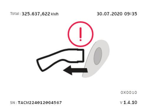
Contents

        7.3      Connect the AC input cable...................................................................................................40
                 7.3.1    Connect the AC input cable, 1 phase (IEC portfolio)....................................... 40
                 7.3.2    Connect the AC input cable, 3 phase (IEC portfolio)....................................... 40
                 7.3.3    Connect the AC input cable (UL portfolio).........................................................41
                 7.3.4    Secure the cables.................................................................................................... 41
        7.4      Communication connections................................................................................................42
                 7.4.1    Insert the Ethernet cable....................................................................................... 42
                 7.4.2    Connect the Ethernet cable.................................................................................. 42
                 7.4.3    Insert the wires for the smart meter communication.....................................43
                 7.4.4    Connect the wires for the smart meter communication................................ 43
                 7.4.5    Insert the Nano-M2M SIM card.............................................................................44
        7.5      Replace the EV charge cable................................................................................................. 44
                 7.5.1    Replace the EV charge cable, 1 phase (IEC portfolio)...................................... 44
                 7.5.2    Replace the EV charge cable, 3 phase (IEC portfolio)......................................45
                 7.5.3    Replace the EV charge cable (UL portfolio).......................................................46

8       Commissioning..................................................................................48
        8.1      General commissioning procedure..................................................................................... 48
        8.2      Energize the EVSE................................................................................................................... 48
        8.3      Set up the EVSE....................................................................................................................... 48

9       Access to parts.................................................................................. 50
        9.1      Remove the cabinet cover..................................................................................................... 50
        9.2      Install the cabinet cover.........................................................................................................50
        9.3      Remove the maintenance cover............................................................................................51
                 9.3.1     Remove the maintenance cover (EVSE without display).................................51
                 9.3.2     Remove the maintenance cover ( EVSE with display)...................................... 51
        9.4      Install the maintenance cover............................................................................................... 52
                 9.4.1     Install the maintenance cover (EVSE without display).................................... 52
                 9.4.2     Install the maintenance cover (EVSE with display).......................................... 52
        9.5      Remove the inner cover.......................................................................................................... 53
                 9.5.1     Remove the inner cover (EVSE without display................................................ 53
                 9.5.2     Remove the inner cover (EVSE with display)..................................................... 53
        9.6      Install the inner cover............................................................................................................. 54
                 9.6.1     Install the inner cover (EVSE without display).................................................. 54
                 9.6.2     Install the inner cover (EVSE with display)........................................................ 54

10      Troubleshooting................................................................................ 55
        10.1     Troubleshooting procedure.................................................................................................. 55
        10.2     Troubleshooting table (IEC portfolio).................................................................................55
        10.3     Troubleshooting table (UL portfolio)..................................................................................58
        10.4     De-energize the EVSE..............................................................................................................61

BCM.V3Y01.0-EN | 002                                                                                                                                   5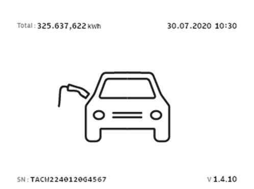
Contents

11         Technical data....................................................................................62
           11.1     EVSE Type..................................................................................................................................62
           11.2     General specifications............................................................................................................ 63
           11.3     Ambient conditions................................................................................................................ 64
           11.4     Mass .......................................................................................................................................... 64
           11.5     Protective device compliance............................................................................................... 65
                    11.5.1     Protective device compliance (IEC portfolio)....................................................65
                    11.5.2     Protective device compliance (UL portfolio).....................................................65
                    11.5.3     Protective device compliance (Singapore)........................................................ 66
           11.6     Parts included in the delivery................................................................................................66
           11.7     Required tools for installation..............................................................................................66
           11.8     Requirements for the wall......................................................................................................67
           11.9     Noise level................................................................................................................................. 67
           11.10    Dimensions............................................................................................................................... 67
                    11.10.1 AC input with socket, cable Type 2......................................................................67
                    11.10.2 AC input with EV charge cable............................................................................. 68
                    11.10.3 Space requirements for installation................................................................... 69
           11.11    AC input specifications.......................................................................................................... 69
                    11.11.1 General specifications........................................................................................... 69
                    11.11.2 400 VAC 3-phase with neutral (TT, TN) (IEC portfolio)................................... 70
                    11.11.3 230 VAC 1-phase (IEC portfolio)...........................................................................70
                    11.11.4 240 VAC (UL portfolio)........................................................................................... 70
                    11.11.5 AC input specifications (IEC portfolio)...............................................................70
                    11.11.6 AC input specifications (UL portfolio)................................................................ 71
           11.12    General logic interface specifications................................................................................. 71
           11.13    Cable specifications................................................................................................................ 71
                    11.13.1 AC input cable (IEC portfolio)............................................................................... 71
                    11.13.2 AC input cable (UL portfolio)................................................................................ 72
                    11.13.3 Ethernet cable specifications............................................................................... 72
                    11.13.4 RS485 cable specifications....................................................................................72
                    11.13.5 Dry contacts input...................................................................................................73
                    11.13.6 Dry contacts output................................................................................................73
                    11.13.7 EV charge cable specifications (IEC portfolio)................................................. 74
                    11.13.8 EV charge cable specifications (UL portfolio)...................................................74
           11.14    AC output specifications....................................................................................................... 74
                    11.14.1 AC output specifications (IEC portfolio)............................................................74
                    11.14.2 AC output specifications (UL portfolio).............................................................74
           11.15    Torque specifications............................................................................................................. 75

6                                                                                                                              BCM.V3Y01.0-EN | 002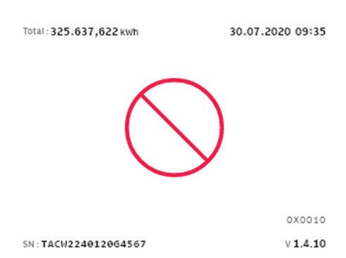
About this document

1               About this document

1.1             Function of this document
                The document is only applicable for this EVSE (Terra AC), including the variants and
                options listed in section 11.1. The EVSE from here on in the document is referred to
                as the EVSE.
                The document gives the information that is necessary to do these tasks:
                •   Installation
                •   Commissioning

1.2             Target group
                The document is intended for qualified installation engineers.
                For a description of the required qualifications, refer to section 3.2.

1.3             Revision history
                Version                       Date                          Description
                001                           March 2020                    Initial version
                002                           April 2021                    Complete document over-
                                                                            haul

1.4             Language
                The original instructions of this document are in English (EN-US). All other language
                versions are translations of the original instructions.

1.5             Illustrations
                It is not always possible to show the configuration of your EVSE. The illustrations in
                this document show a typical setup. They are for instruction and description only.

1.6             Units of measurement
                SI units of measurement (metric system) are used. If necessary, the document
                shows other units between parentheses () or in separate columns in tables.

1.7             Typographical conventions
                The lists and steps in procedures have numbers (123) or letters (abc) if the sequence
                is important.

1.8             How to use this document
                1. Make sure that you know the structure and contents of this document.
                2. Read the safety chapter and make sure that you know all the instructions.

BCM.V3Y01.0-EN | 002                                                                                  7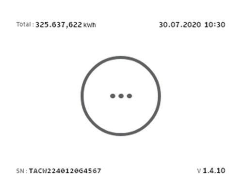
About this document

                3. Do the steps in the procedures fully and in the correct sequence.
                4. Keep the document in a safe location that you can easily access. This document
                   is a part of the EVSE.

1.9             General symbols and signal words
                Signal word          Description                                  Symbol
                Danger               If you do not obey the instruction, this     Refer to section
                                     can cause injury or death.                   1.10.
                Warning              If you do not obey the instruction, this     Refer to section
                                     can cause injury.                            1.10.
                Caution              If you do not obey the instruction, this
                                     can cause damage to the EVSE or to
                                     property.

                Note                 A note gives more data, to make it easier
                                     to do the steps, for example.

                -                    Information about the condition of the
                                     EVSE before you start the procedure.

                -                    Requirements for personnel for a proce-
                                     dure.

                -                    General safety instructions for a proce-
                                     dure.

                -                    Information about spare parts that are
                                     necessary for a procedure.

                -                    Information about support equipment
                                     that is necessary for a procedure.

                -                    Information about supplies (consuma-
                                     bles) that are necessary for a procedure.

                -                    Make sure that the power supply to the
                                     EVSE is disconnected.

8                                                                                BCM.V3Y01.0-EN | 002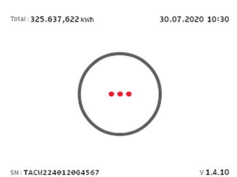
About this document

                Signal word           Description                                Symbol
                -                     Electrotechnical expertise is required,
                                      according to the local rules.

                -                     Alternating current supply

                          Note: It is possible that not all symbols or signal words are present in
                          this document.

1.10            Special symbols for warnings and dangers
                Symbol                       Risk type
                                             General risk

                                             Hazardous voltage that gives risk of electrocution

                                             Risk of pinching or crushing of body parts

                                             Rotating parts that can cause a risk of entrapment

                          Note: It is possible that not all symbols are present in this document.

1.11            Related documents
                Document name                               Target group
                Product data sheet                          All target groups
                Installation manual                         Qualified installation engineer
                User manual                                 Owner
                Declaration of conformity (CE)              All target groups

                You can find all related documents here: https://new.abb.com/ev-charging/terra-
                ac-wallbox.

BCM.V3Y01.0-EN | 002                                                                                 9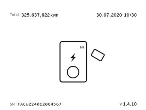
About this document

1.12            Manufacturer and contact data

                Manufacturer
                ABB EV Infrastructure
                George Hintzenweg 81
                3068 AX, Rotterdam
                The Netherlands

                Contact data
                ABB EV Infrastructure in your country can give you support on the EVSE. You can
                find the contact data here: https://new.abb.com/ev-charging

1.13            Abbreviations
                Abbreviation                Definition
                AC                          Alternating current
                CAN                         Controller area network
                CPU                         Central processing unit
                DC                          Direct current
                EMC                         Electromagnetic compatibility
                EV                          Electric vehicle
                EVSE                        Electric vehicle supply equipment
                MID                         Measuring Instruments Directive
                NFC                         Near field communication
                NoBo                        Notified body
                OCPP                        Open charge point protocol
                PE                          Protective earth
                PPE                         Personal protective equipment
                RFID                        Radio-frequency identification

                          Note: It is possible that not all abbreviations are present in this
                          document.

1.14            Terminology
                Term                        Definition
                Network operating center    Facility of the manufacturer to do a remote check on
                of the manufacturer         the correct operation of the EVSE
                Cabinet                     Enclosure of the EVSE, including the components on
                                            the inside
                Contractor                  Third party that the owner or site operator hires to do
                                            engineering, civil and electrical installation work

10                                                                              BCM.V3Y01.0-EN | 002
About this document
Term Definition
Grid provider Company that is responsible for the transport and dis-
tribution of electricity
Local rules All rules that apply to the EVSE during the entire lifecy-
cle of the EVSE. The local rules also include the national
laws and regulations.
Open charge point proto- Open standard for communication with charge sta-
col tions
Owner Legal owner of the EVSE
Site operator Entity that is responsible for the day-to-day control of
the EVSE. The site operator does not have to be the
owner.
User Owner of an EV, who uses the EVSE to charge the EV
Note: It is possible that not all terms are present in this document.
1.15 Orientation agreements
Z
Y X
D
B
A
C
A Front side: face forward to the X X-direction (positive is to the right)
EVSE during normal use Y Y-direction (positive is rearward)
B Left side Z Z-direction (positive is upward)
C Right side
D Rear side
BCM.V3Y01.0-EN | 002 11Description
2 Description
2.1 Short description
The EVSE (Terra AC) is an AC charging station that you can use to supply electricity
to an EV. The Terra AC offers tailor-made, intelligent and network charging
solutions for your company or home. The EVSE can connect to the internet via GSM,
WiFi or LAN.
2.2 Intended use
The EVSE is intended for the AC charging of EVs. The EVSE is intended for indoor or
outdoor use.
The technical data of the EVSE must comply with the properties of the electrical
grid, the ambient conditions and the EV. Refer to chapter 11.
Only use the EVSE with accessories that the manufacturer provides or that obey the
local rules.
The EVSE AC input is intended for a hardwired installation that complies with the
applicable national regulations.
Danger:
General risk
• If you use the EVSE in any other way than described in the related
documents, you can cause death, injury and damage to property.
• Use the EVSE only as intended.
2.3 Product label (IEC portfolio)
A I
XXX XXXX
J
K
Cert. No. xxxx/xxxxxxx
Checksum: xxxxxxxx
FW Version xxxxxx L
B M
C TAC Wxx-[L]-WWYY-zxxxx
D XXXXXXXXXX
E Terra AC W22-T-RD-M-0 50Hz
Active energie Cl. B (1) 1000imp/kWh
3x220/380...3x240/415V- -30ºC-55ºC
F 0.25-5(32)A 2020-39 N
Weight: 3.0kg
G
George Hintzenweg 81,
3068 AX, Rotterdam, IP54
The Netherlands
H
Made in China www.abb.com O
12 BCM.V3Y01.0-EN | 002Description
A Brand I CE mark
B Barcode with the serial number J MID mark and notified body
C Barcode with the part number of number
the EVSE K MID certificate number
D Product model number L MID software checksum
E MID accuracy class M MID FW version
F EVSE rating N Ingress protection rating
G Mass of the EVSE O Reference to the manual
H Address of the manufacturer
Note: The data in the illustration is only an example. Find the product
label on your EVSE to see the applicable data. Refer to section 2.6.2.
2.4 Product label (UL portfolio)
SN: TACW7-[L]-WWYY-zxxxx
A
PN: XXXXXXXXXX
B
MODEL: Terra AC WX-P8-XX-XXX-X
C
D
TAC Wx-[L]-WWYY-zxxxx
E
XXXX XXXXXX
For use with electric vehicles
Pour utilisation avec des véhicules électriques G
240V ~ / 60Hz 32A TYPE 3 -30ºC~50ºC
F Ventilation Not Required Aucune ventilation requise
Raintight Étanche à la pluie Weight: 7.0kg
Dusttight Étanche à la poussière Poids: 7.0kg H
A Serial number E Barcode with the part number of
B Part number of the EVSE the EVSE
C Product model number F Power rating of the EVSE
D Barcode with the serial number of G Ambient temperature
the EVSE H Mass of the EVSE
Note: The data in the illustration is only an example. Find the product
label on your EVSE to see the applicable data. Refer to section 2.6.2.
BCM.V3Y01.0-EN | 002 13Description
2.5 Working principle
A B C D E F G
4G RFID
H
1 1
* * * * *
CPU
3
* * I
* * 2
* 3
* * M
* P
* 2
IN K L N O OUT
4 4 4 4 4 4 4
J Q
A LEDs I AC/DC power supply
B Ethernet J AC input
C WiFi K Surge protection
D 4G L Earth(ground) fault protection
E RFID M AC input metering
F Bluetooth N AC isolation relay
G CPU system O Control pilot
H Isolation P AC output
1. The user initiates a charge session request (black lines).
2. The EVSE verifies the status of the EV (purple lines).
3. The EVSE goes on and AC power goes to the EV (yellow lines).
4. The charge session starts. AC power flows from the power grid to the EV (red
lines).
5. The electrical interfaces of the EVSE communicate with the on-board computer
(blue lines).
(*): Connections between parts of the EVSE and the CPU system. The arrow shows
the direction of the input and output signals.
14 BCM.V3Y01.0-EN | 002Description
2.6 Overview
2.6.1 Overview of the system
A B
E
F
G
D C
A EVSE E RFID card or smartphone
B AC grid input F Structure to install the EVSE on
C EV G EV charge cable
D Parking space
Part Function
EVSE Refer to section 2.2.
Structure To install the EVSE on and to keep the
EVSE in position.
AC grid input To supply the electricity to the EVSE
EV charge cable To conduct the current from the EVSE to
the EV
EV The EV of which the batteries need to be
charged
Parking space Location for the EV during the charge
session
RFID card or smartphone To authorize the user to use the EVSE
2.6.2 Overview of the EVSE, outside
Note: The illustration shows the EVSE model without a display.
BCM.V3Y01.0-EN | 002 15Description
G
F
H
I
E
A
B C D
A Connection for the EV charge cable F Cabinet cover
B Openings for the smart meter G Enclosure
connections H RFID reader
C Opening for the Ethernet cable I Product label
D Opening for the AC input cable
E LED indicators
Part Function
Connection for the EV To connect the EV charge cable
charge cable
Openings Openings for the cables that go into the EVSE
LED indicators To show the status of the EVSE and the charge ses-
sion. Refer to section 2.8.1.
Cabinet cover To prevent a user to access the installation and main-
tenance parts of the EVSE
Enclosure To reduce the accessibillity of unqualified persons to
the inside of the EVSE
RFID reader To authorize the start or stop of a charging session
with an RFID card
Product label To show the identification data of the EVSE. Refer to
section 2.3.
16 BCM.V3Y01.0-EN | 002Description
2.6.3 Overview of the EVSE, inside (CE model)
A B C
D
E
F
G
A Maintenance cover E Terminal block for dry contacts
B Primary Ethernet connection input and output
C Socket for a Nano-M2M SIM card F Terminal block for the AC input
D Smart meter connection G Terminal block for the EV charge
cable or the socket
Part Function
Maintenance cover To prevent access to the electrical components of the
EVSE
Primary Ethernet connec- To connect the Ethernet cable
tion
Socket for a Nano-M2M To connect the EVSE to the internet 4G
SIM card
Smart meter connection To connect the cables for Modbus RTU - RS485
Terminal block for dry con- Not used
tacts input and output
Terminal block for the AC To connect the AC input cable from the grid
input
Terminal block for the EV To connect the EV charge cable or the socket outlet
charge cable
BCM.V3Y01.0-EN | 002 17Description
2.6.4 Overview of the EVSE, inside (MID model)
A B C D
E
F
G
H
I
A Maintenance cover F Secondary Ethernet connection
B Primary Ethernet connection G Smart meter connection
C Electrical pulse connector H Terminal block for dry contacts
D Socket for a Nano-M2M SIM card input and output
E Terminal block for the AC input I Terminal block for the EV charge
cable or the socket
Part Function
Maintenance cover To prevent access to the electrical components of the
EVSE
Primary Ethernet connec- To connect the Ethernet cable
tion
Electrical pulse connector Use for manufacturer only. Do not change or connect
cables to this input yourself.
Socket for a Nano-M2M To connect the EVSE to the internet 4G
SIM card
Terminal block for the AC To connect the AC input cable from the grid
input
Secondary Ethernet con- To use one Ethernet cable connection for multiple EV-
nection SEs. There is no communication between the EVSEs.
Smart meter connection To connect the cables for Modbus RTU - RS485
Terminal block for dry con- Not used
tacts input and output
Terminal block for the EV To connect the EV charge cable or the socket outlet
charge cable
18 BCM.V3Y01.0-EN | 002Description
2.6.5 Overview of the EVSE, inside (UL model)
A B C
D
E
F
G
H
A Maintenance cover E Smart meter connection
B Primary Ethernet connection F Terminal block for dry contacts
C Socket for a Nano-M2M SIM card input and output
D Secondary Ethernet connection G Terminal block for the AC input
H Terminal block for the EV charge
cable or the socket
Part Function
Maintenance cover To prevent access to the electrical components of the
EVSE
Primary Ethernet connec- To connect the Ethernet cable
tion
Socket for a Nano-M2M To connect the EVSE to the internet 4G
SIM card
Secondary Ethernet con- To use one Ethernet cable connection for multiple EV-
nection SEs. There is no communication between the EVSEs.
Smart meter connection To connect the cables for Modbus RTU - RS485
Terminal block for dry con- Not used
tacts input and output
Terminal block for the AC To connect the AC input cable from the grid
input
Terminal block for the EV To connect the EV charge cable or the socket outlet
charge cable or the socket
BCM.V3Y01.0-EN | 002 19Description
2.6.6 Overview of the EVSE, inside (UL model with display)
A B C
D
E
F
G
H
A Maintenance cover E Secondary Ethernet connection
B Primary Ethernet connection F Smart meter connection
C Socket for a Nano-M2M SIM card G Terminal block for dry contacts
D Terminal block for the AC input input and output
H Terminal block for the EV charge
cable or the socket
Part Function
Maintenance cover To prevent access to the electrical components of the
EVSE
Primary Ethernet connec- To connect the Ethernet cable
tion
Socket for a Nano-M2M To connect the EVSE to the internet 4G
SIM card
Terminal block for the AC To connect the AC input cable from the grid
input
Secondary Ethernet con- To use one Ethernet cable connection for multiple EV-
nection SEs. There is no communication between the EVSEs.
Smart meter connection To connect the cables for Modbus RTU - RS485
Terminal block for dry con- Not used
tacts input and output
Terminal block for the EV To connect the EV charge cable or the socket outlet
charge cable or the socket
20 BCM.V3Y01.0-EN | 002Description
2.7 Options
2.7.1 Display
A
A Display
For more data about the display, refer to section 2.10.
2.7.2 EV charge cable, Type 2
2.7.3 Socket, Type 2
A
A Socket
BCM.V3Y01.0-EN | 002 21Description
The socket for an EV charge cable Type 2 is available with or without a shutter.
2.7.4 EV charge cable, Type 1 (UL portfolio)
2.7.5 4G Communication
You can connect to a 4G network.
2.7.6 Load management
Load management makes sure that the available electrical capacity of the building
or home is not exceeded. A number of devices share a grid connection, that has a
maximum capacity. The total power demand of the devices that use the grid
connection must not exceed the grid capacity.
The load management feature prevents that the system exceeds the grid capacity
and prevents damage of the fuses. At times when the current demand is high, the
EVSE decreases the output of current. The current will increase again when there is
availability on the grid.
Also, the load management feature makes sure that the available load is optimally
shared.
22 BCM.V3Y01.0-EN | 002Description
2.8 Control elements
2.8.1 LED indicators
A
B
C
D
E
A Error LED D Internet connection LED
B Charging LED E EVSE on/off LED
C Cable and EV detection, and EV
authorization LED
Table 1: Error LED
Status of the LED Status of the EVSE
On Error
Off No error
Table 2: Charging LED
Status of the LED Status of the EVSE
On EV is fully charged or has stopped
charging
Off Not charging
Flashing Charging
BCM.V3Y01.0-EN | 002 23Description
Table 3: Cable and EV detection, and EV authorization LED
Status of the LED Status of the EVSE
On An EV is connected. The connection is
authorized.
Off No EV connected
Flashing A EV is connected, waiting for authoriza-
tion
Table 4: Internet connection LED
Status of the LED Status of the EVSE
On Connected to the internet
Off Not connected to the internet
Flashing In progress to establish internet con-
nection
Table 5: EVSE on/off LED
Status of the LED Status of the EVSE
On The EVSE is on
Off The EVSE is off
Flashing The EVSE is in setup
2.9 TerraConfig app to do the commissioning
The TerraConfig app is available on the Apple Store and on the Google Play Store.
The app is necessary to do the commissioning.
2.10 Description of the display screens (option)
2.10.1 Boot screen
During the start up of the EVSE, the display shows the Boot screen.
24 BCM.V3Y01.0-EN | 002Description
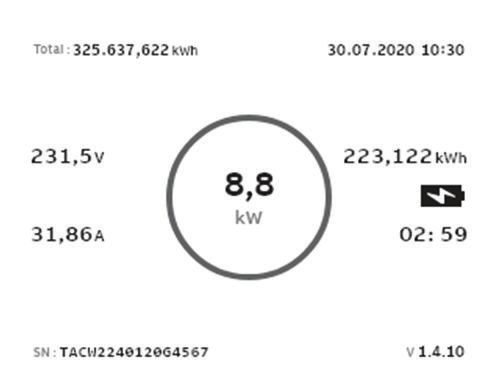
2.10.2 Standby/Idle screen
A B
Total : 325.634,622 KWh 30.07.2020 10:30
SN : TACW2240120G4567 v 00.55.19
C D E
A Total delivered energy D Serial number
B Date E Firmware version (MID certified)
C Guide
The display shows the Standby/Idle screen when the EVSE is in idle status. Then,
the EVSE is available for a charge session.
2.10.3 Authorization screen
The display shows different Authorization screens, dependent on the situation.
The display shows this Authorization screen when the EV charge cable is connected
to the EV but the charge session is not authorized:
Total : 325.637,622 kWh 30.07.2020 10:30
SN : TACW2240120G4567 v 00.55.19
The display shows this Authorization screen when the charge session is authorized
but the EV charge cable is not connected to the EV:
Total : 325.637,622 kWh 30.07.2020 10:30
SN : TACW2240120G4567 v 00.55.19
BCM.V3Y01.0-EN | 002 25Description
2.10.4 Preparing to charge screen
Total : 325.637,622 kWh 30.07.2020 10:30
SN : TACW2240120G4567 v 00.55.19
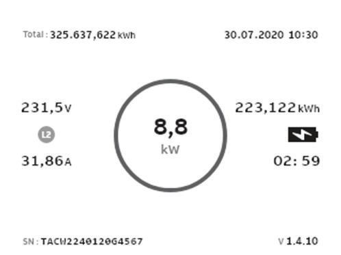
2.10.5 Charging screen
The display shows the Charging screen during the charge session.
The display shows this Charging screen for a single phase EVSE:
A B C
Total : 325.637,622 kWh 30.07.2020 10:30
231,5V 20,180kWh
7,3
kW
31,86A 02:41
SN : TACW2240120G4567 v 00.55.19
A Real-time voltage and current C Energy delivered and duration of
B Real-time active power the charge session
The display shows this Charging screen for a 3 phase EVSE:
A
Total : 325.637,622 kWh 30.07.2020 09:28
231,5V 60,541kWh
21,9
kW
31,86A 02:41
SN : TACW2240120G4567 v 00.55.19
A Real-time voltage and current per
phase
26 BCM.V3Y01.0-EN | 002Description
2.10.6 Charging completed screen
A B
Total : 325.637,622 kWh 30.07.2020 09:35
30.07.2020 06:54 - 30.07.2020 09:35
60,541kWh 02:41
SN : TACW2240120G4567 v 00.55.19
A Start and end time B Energy delivered and duration of
the charge session
2.10.7 Fault detected display messages
The display shows different fault detected images, dependent on the type of fault.
Disconnect the charge cable and connect it again:
Total : 325.637,622 kWh 30.07.2020 09:35
0x0010
SN : TACW2240120G4567 v 00.55.19
A
A Error code
Contact your service provider:
Total : 325.637,622 kWh 30.07.2020 09:35
0x0010
SN : TACW2240120G4567 v 00.55.19
A
A Error code
BCM.V3Y01.0-EN | 002 27Description
The EV is not ready for the charge session:
Total : 325.637,622 kWh 30.07.2020 10:30
SN : TACW2240120G4567 v 00.55.19
28 BCM.V3Y01.0-EN | 002Safety
3 Safety
3.1 Liability
The manufacturer is not liable to the purchaser of the EVSE or to third parties for
damages, losses, costs or expenses incurred by the purchaser or third parties if any
target group mentioned in the related documents does not obey the rules below:
• Obey the instructions in the related documents. Refer to section 1.11.
• Do not misuse or abuse the EVSE.
• Only make changes to the EVSE, if the manufacturer approves in writing of the
changes.
This EVSE is designed to be connected to and to communicate information and
data via a network interface. It is the sole responsibility of the owner to provide and
continuously ensure a secure connection between the EVSE and the network of the
owner or any other network.
The owner shall establish and maintain any appropriate measures (such as - but not
limited to - the installation of firewalls, application of authentication measures,
encryption of data and installation of anti-virus programs) to protect the EVSE, the
network, its system and the interface against any kind of security breaches,
unauthorized access, interference, intrusion, leakage and/or theft of data or
information.
The manufacturer is not liable for damages and/or losses related to such security
breaches, any unauthorized access, interference, intrusion, leakage and/or theft of
data or information.
3.2 Required qualifications for the installation engineer
• The qualified installation engineer fully knows the EVSE and its safe installation.
• The installation engineer is qualified according to the applicable local rules to do
the work.
• The qualified installation engineer obeys all local rules and the instructions in
the installation manual.
• It is the responsibility of the owner of the EVSE to make sure that all qualified
installation engineers obey the local rules, the installation instructions, and the
specifications of the EVSE.
3.3 Personal protective equipment
Symbol Description
Protective clothing
Safety gloves
BCM.V3Y01.0-EN | 002 29Safety
Symbol Description
Safety shoes
Safety glasses
3.4 FCC compliance statement
Caution: Changes or modifications not expressly approved by the party
responsible for compliance could void the user's authority to operate the
equipment.
Note: This equipment has been tested and found to comply with the
limits for a Class B digital device, pursuant to part 15 of the FCC Rules.
These limits are designed to provide reasonable protection against
harmful interference in a residential installation. This equipment
generates, uses and can radiate radio frequency energy and, if not
installed and used in accordance with the instructions, may cause
harmful interference to radio communications. However, there is no
guarantee that interference will not occur in a particular installation. If
this equipment does cause harmful interference to radio or television
reception, which can be determined by turning the equipment off and on,
the user is encouraged to try to correct the interference by one or more
of the following measures:
• Reorient or relocate the receiving antenna.
• Increase the separation between the equipment and receiver.
• Connect the equipment into an outlet on a circuit different from that
to which the receiver is connected.
• Consult the dealer or an experienced radio/TV technician for help.
3.5 Industry Canada compliance statement
This device contains licence-exempt transmitter(s)/receiver(s) that comply with
Innovation, Science and Economic Development Canada’s licence-exempt RSS(s).
Operation is subject to the following two conditions:
• This device may not cause interference.
• This device must accept any interference, including interference that may cause
undesired operation of the device.
RF exposure statement
This equipment complies with IC radiation exposure limits set forth for an
uncontrolled environment. This equipment should be installed and operated with
minimum distance 20cm between the radiator and your body.
30 BCM.V3Y01.0-EN | 002Safety
3.6 General safety instructions
• This document, the related documents and the warnings included do not
replace your responsibility to use your common sense when you do work on the
EVSE.
• Only do the procedures that the related documents show and that you are
qualified for.
• Obey the local rules and the instructions in this manual. If the local rules
contradict the instructions in this manual, the local rules will apply.
If and to the extent permitted by law, in case of inconsistency or contradiction,
between any requirements or procedure contained in this document and any
such local rules, obey the stricter between the requirements and procedures
specified in this document and the local rules.
3.7 Signs on the EVSE
Symbol Risk type
General risk
Hazardous voltage that gives risk of electrocution
Risk of pinching or crushing of body parts
Rotating parts cat can cause a risk of entrapment
PE
Sign that means that you must read the manual before
you install the EVSE
Waste from electrical and electronic equipment
Note: It is possible that not all symbols are present on the EVSE.
BCM.V3Y01.0-EN | 002 31Safety
3.8 Discard the EVSE or parts of the EVSE
Incorrect waste handling can have a negative effect on the environment and human
health due to potential hazardous substances. With the correct disposal of this
product, you contribute to reuse and recycling of materials and protection of the
environment.
• Obey the local rules to discard parts, packaging material or the EVSE.
• Discard electrical and electronic equipment separately in compliance with the
WEEE - 2012/19/EU Directive on waste of electrical and electronic equipment.
• As the symbol of the crossed out wheeled-bin on your EVSE indicates, do not
mix or dispose the EVSE with your household waste, at the end of use. Instead,
hand the EVSE over to your local community waste collection point for recycling.
• For more information, contact the Government Waste-Disposal department in
your country.
3.9 Safety instructions for earthing
Preliminary requirements
•
• Make sure that the EVSE is connected to a grounded, metal, permanent wiring
system, or an equipment-grounding conductor must be run with the circuit
conductors and connected to the equipment grounding terminal or lead on the
product.
• Make sure that the connections to the EVSE comply with all applicable local
rules.
3.10 Special safety instructions (IEC portfolio)
3.10.1 Safety instructions during installation
Preliminary requirements
1. •
• Make sure that there is no voltage on the AC input cables during the complete
installation procedure.
• Keep unqualified personnel at a safe distance during installation.
• Only use electrical wires of sufficient gauge and insulation to handle the rated
current and voltage demand.
• Make sure that the load capacity of the grid is in accordance with the EVSE.
32 BCM.V3Y01.0-EN | 002Safety
• Earth the EVSE correctly. Refer to section 3.9.
• Make sure that the wiring inside the EVSE is protected from damage and cannot
get trapped when you open or close the cabinet.
• Make sure that water cannot enter the cabinet.
• Protect the EVSE with safety devices and measures that the local rules specify.
• If it is necessary to remove safety devices, immediately install the safety devices
after the work.
• Put on the correct personal protective equipment. Refer to section 3.3.
3.11 Special safety instructions (UL portfolio)
3.11.1 Additional important safety instructions
Warning: Obey the basic precautions for electric products, including the
instructions in this section.
Caution: To reduce the risk of fire, connect this EVSE only to a circuit
provided with 40 A maximum branch circuit overcurrent protection in
accordance with the National Electrical Code, ANSI/NFPA 70.
• Read all the instructions befor you use this EVSE.
• Make sure that adults supervise this EVSE is when it is used around children.
• Do not put fingers into the EV connector.
• Do not use this product if the flexible power cord or EV charge cable is frayed,
has broken insulation, or any other signs of damage.
• Do not use this EVSE if the enclosure or the EV connector is broken, cracked,
open, or shows any other indication of damage.
• Install an insulated grounding conductor that is identical in size, insulation
material, and thickness to the grounded and ungrounded branch-circuit supply
conductors, except that it is green with or without one or more yellow stripes,
as part of the branch circuit that supplies the EVSE.
• Connect the grounding connector of the previous bullet point to earth at the
EVSE or, when supplied by a separately derived system, at the supply
transformer.
• For the AC power input wiring installation, refer to section 11.11.4.
• For the torque requirements for the screws of the terminal block for the AC
power, refer to section 11.15.
SAVE THESE INSTRUCTIONS
BCM.V3Y01.0-EN | 002 33Installation
4 Installation
4.1 General installation procedure
Preliminary requirements
1. All required permits to • There is no voltage on the
agree with the local rules AC input cable during the
are granted. complete installation
2. The AC input cable is procedure.
available.
• Tools for installation. Refer
to section 11.7.
Procedure
1. Unpack the EVSE. Refer to section 4.2.
2. Prepare the site. Refer to chapter 5.
3. Remove the cabinet cover. Refer to section 9.1.
4. Do the mechanical installation. Refer to section 6.1.
5. Do the electrical installation. Refer to section 7.1.
6. Install the cabinet cover. Refer to section 9.2.
7. Do the commissioning procedure. Refer to section 8.1.
4.2 Unpack the EVSE
1. Open the box.
2. Remove the EVSE from the box.
3. Remove all packaging material from the EVSE.
4. Discard the packaging material. Refer to section 3.8.
5. Make sure that all parts are delivered according to the order. Refer to the order
and section 11.6.
6. Do an inspection of the EVSE and the parts for installation for damage.
7. If you find damage or the parts are not according to the order, contact the local
representative of the manufacturer (ABB EV Infrastructure). Refer to section
1.12.
34 BCM.V3Y01.0-EN | 002Site preparation
5 Site preparation
5.1 Select the site
1. Find a suitable site on a wall. For the specifications of the wall, refer to section
11.8.
2. Make sure that the correct power supply is available. For the power supply
specifications, refer to section 11.11.
3. Obey the space requirements. Refer to section 11.10.3.
5.2 Prepare the site (IEC portfolio)
Preliminary requirements
1. The site must be suitable to install the EVSE. Refer to section 5.1.
Note:
Information for MID certified EVSE:
• The meter is intended to be installed in a Mechanical Environment
'M1', with Shock and Vibrations of low significance, as per 2014/32/
EU Directive.
• The meter is intended to be installed in Electromagnetic Environment
'E2', as per 2014/32/EU Directive.
Procedure
1. Make sure that the space and the airflow around the EVSE are sufficient. Refer
to section 11.10.3.
2. Make sure that the correct cables are available at the site.
• AC input cable. Refer to section 11.13.
• RS485 cable. Refer to section 11.13.4.
• Ethernet cable. Refer to section 11.13.3.
5.3 Prepare the site (UL portfolio)
Preliminary requirements
1. The site must be suitable to install the EVSE. Refer to section 5.2.
Procedure
1. Make sure that the space and the airflow around the EVSE are sufficient. Refer
to section 11.10.3.
2. Make sure that the correct cables are available at the site.
• AC input cable. Refer to section 11.13.2.
• RS485 cable. Refer to section 11.13.4.
• Ethernet cable. Refer to section 11.13.3.
BCM.V3Y01.0-EN | 002 35Site preparation 36 BCM.V3Y01.0-EN | 002
Mechanical installation

6               Mechanical installation

6.1             General mechanical installation procedure
                             Note: The mounting screws and plugs that are included in the delivery
                             are serviceable for a brick wall. If you want to mount the EVSE on a
                             different type of wall, contact your local representative of the
                             manufacturer (ABB EV Infrastructure).
                1. Prepare the holes for the mounting screws. Refer to section 6.2.
                2. Install the upper mounting screws. Refer to section 6.3.
                3. Install the EVSE on the site. Refer to section 6.4.

6.2             Prepare the holes for the mounting screws
                Preliminary requirements

                         •     Spirit level                          •   Installation template. Refer
                         •     Drill                                     to section 11.6.
                                                                     •   Plugs for the upper
                                                                         mounting holes. Refer to
                                                                         section 11.6
                                                                     •   Plugs for the lower
                                                                         mounting holes. Refer to
                                                                         section 11.6.

                Procedure
                1. Hold the installation template (A)
                   against the wall.                                               A     B
                2. Make sure that the installation is level.
                   Use the spirit level.
                3. Mark the location for the mounting                    D
                   holes (B) and (C).
                4. Drill the upper mounting holes (B) and
                   the lower mounting holes (C).
                                Note: For the diameter of
                                the holes, refer to the plugs            E
                                for the upper and lower
                                                                                         C
                                mounting holes.

                5. Insert the plugs for the upper
                   mounting holes (D) in the upper
                   mounting holes.
                6. Insert the plugs for the lower mounting holes (E) in the lower mounting holes

BCM.V3Y01.0-EN | 002                                                                                 37
Mechanical installation
6.3 Install the upper mounting screws
Preliminary requirements
1. The plugs for the upper • Upper mounting screws.
and lower mounting Refer to section 11.6.
screws are installed.
Procedure
1. Install the upper mounting screws (A)
B
in the upper holes (B).
2. Make sure that a length (X) of the X
screws stays out of the wall. For the
specification, refer to section 11.8.
A
This length outside the wall is
necessary to suspend the EVSE.
6.4 Install the EVSE on the wall
Preliminary requirements
1. The upper mounting • Lower mounting screws.
screws are installed. Refer to section 11.6.
Procedure
1. Put the openings (A) over the upper
mounting screws (B).
B
The upper mounting screws support
the EVSE.
2. Install the lower mounting screws (C).
For the torque specifications, refer to
section 11.15. A
C
38 BCM.V3Y01.0-EN | 002Electrical installation
7 Electrical installation
7.1 General electrical installation procedure
Preliminary requirements
•
Procedure
1. Remove the maintenance cover. Refer to section 9.3.
2. Install the AC input cable.
• Insert the AC input cable. Refer to section 7.2.
• Connect the AC input cable. Refer to section 7.3.
3. Install the Ethernet cable.
• Insert the Ethernet cable. Refer to section 7.4.1.
• Connect the Ethernet cable. Refer to section 7.4.2.
4. If necessary, install the cables for smart meter communication.
• Insert the cables for smart meter communication. Refer to section 7.4.3.
• Connect the cables for smart meter communication. Refer to section 7.4.4.
5. If you want to use the internet, insert the Nano-M2M SIM card. Refer to section
7.4.5.
6. If necessary, replace the EV charge cable. Refer to section 7.5.
7. Install the maintenance cover. Refer to section 9.4.
7.2 Insert the AC input cable
Preliminary requirements
• Screwdriver • AC input cable
BCM.V3Y01.0-EN | 002 39Electrical installation
Procedure
1. Remove the grommet (A) from the
EVSE. A
2. Make a hole in the center of the
grommet.
3. Install the grommet.
4. Strip the wires. For the specification,
refer to section 11.13. B
5. Push the wires through the grommet.
6. Put the AC input cable (B) through the
inlet hole.
7.3 Connect the AC input cable
7.3.1 Connect the AC input cable, 1 phase (IEC portfolio)
Preliminary requirements
• Torque screwdriver • AC input cable (1 phase)
Procedure
1. Loosen the screws (A). B A
2. Strip the wires. For the specification,
refer to section 11.13.1.
3. Insert the cable connector into the
terminal block (B).
4. Connect the below wires:
1. Earthing wire (C)
E
2. Neutral wire (D)
3. AC input wire (E)
C
Refer to section 11.11.
D
5. Tighten the screws (A) to the correct
torque. For the specification, refer to
section 11.15.
7.3.2 Connect the AC input cable, 3 phase (IEC portfolio)
Preliminary requirements
• Torque screwdriver • AC input cable (3 phase, TN,
TT networks)
40 BCM.V3Y01.0-EN | 002You can also read