INNOVATION Engineer Wärtsilä breaking the record The first digital twin: Apollo 13 - Siemens PLM
←
→
Page content transcription
If your browser does not render page correctly, please read the page content below
Engineer

INNOVATION                     Issue 5

In this issue

Wärtsilä breaking
the record
Page 4

The first digital
twin: Apollo 13
Page 10

Interview:
ElectraMeccanica...
Forbes Magazine's
Coolest Car 2020
Page 26

                      siemens.com/simcenter
Engineer Innovation | Firsts
                                             Aerospace
                                                    and record breakers

                                                                              Firsts and record breakers
                                                                          These are very difficult and strange          that can take off vertically and switch
                                                                          times, and I wanted to extend my              to flying horizontally, whilst carrying
                                                                          thoughts and well wishes to you and           a payload of 16kilograms for eight
                                                                          hope that you and your family are safe        hours. Clean Motion designed and
                                                                          and well. I am fortunate in my role           built an electric tuk-tuk and then went
                                                                          that I receive one of the first copies of     further by designing a micro-factory
                                                                          Engineer Innovation, I need to read the       to take manufacturing local. And
                                                                          stories to write this introduction. And       ElectraMeccanica’s SOLO which went
                                                                          what really struck me in this issue, is the   from concept design to production in
                                                                          firsts and record breakers showcasing         just eight months.
                                                                          their successes and how Simcenter has
                                                                          supported them along the way.                 Engineers continuing to challenge the
Siemens PLM Software

                                                                                                                        status-quo with innovations to deliver
                                                                          We kick off this issue with a record-         solutions to our everyday challenges,
                                                                          breaking diesel engine from Wärtsilä,         and quickly.
                                                                          the most economical diesel engine
                                                                          ever built. CO2 emissions from shipping       Lastly I was struck by the extraordinary
                                    Jan Leuridan
                                                                          contribute 3 percent to total global          parallels between the Apollo 13 mission
                                    Senior Vice President
                                    Simulation and Test Solutions         greenhouse gas emissions and growing;         and Team INEOS UK’s America’s Cup
                                                                          innovations like this become critical.        dreams. Separated by 50 years, and
                                                                          Another record-breaker is the Daniel          arguably 200,000 miles, the use of
                                                                          K Inouye Solar Telescope, the world’s         digital twins to simulate real situations
                                                                          largest solar telescope, which has the        whether they be unrealised or
                                                                          opposite problem, too much energy in          inaccessible shows the extent of human
                                                                          the form of heat to be dissipated.            achievement. As ever the Simcenter
                                                                                                                        team are incredibly proud to be part of
                                                                          Other notable firsts in this issue are        our customers’ success. n
                                                                          Martin UAV who have launched a drone

                       2
Contents | Engineer Innovation

Contents                                                                        10                                            32

                                                                                 4

                                                                                     24

Engineer Innovation                                                                  Regular Features
4
  COVER: Wärtsilä Breaking the             56
                                              INEOS TEAM UK: A dramatically          10   The first digital twin: Apollo 13
  record                                      different design
                                                                                     26
                                                                                        Interview: ElectraMeccanica...
18
   Hager Group: Cable Trunking             62
                                              Karma Automotive resurrects iconic        Forbes Magazine's Coolest Car 2020
   Systems                                    electric vehicle using Siemens
                                              solutions                              86
                                                                                        GEEK HUB: Mountains are not just
22
   HASETRI keep the wheels of                                                           funny, they are hill areas
   innovation turning                      66
                                              Sofegi: Predictive modeling of
                                              liquid-cooled charge-air cooler heat   90
                                                                                        Brownian Motion: Coughs and
28
   IRKUT Corporation: Introducing             exchanges                                 Sneezes Spread Diseases
   system simulation for aircraft
   system development                      70
                                              Clean Motion: Sometimes the
                                              simplest ideas can change the world
32
   Martin UAV: The rise of the V-Bat
                                           74
                                              Hilti reduce vibration, increasing
36   Maya HTT: Life on Mars                   permissible daily use by 300 percent

42
   Efficient durability testing by Roush   78
                                              Cerebrum-Ingénierie: Delivering
   Industries Inc.                            control algorithms four times faster

46
   Cooling the world’s largest solar       82
                                              Closing the loop: Mechanical
   telescope                                  qualification testing for space
                                              hardware
50
   consilab GmbH: Securing piping in
   the process industry against
   pressure surge

                                                                                                                               3
Engineer Innovation | Marine

    Breaking the record
    How Wärtsilä created the world’s most
    efficient engine

4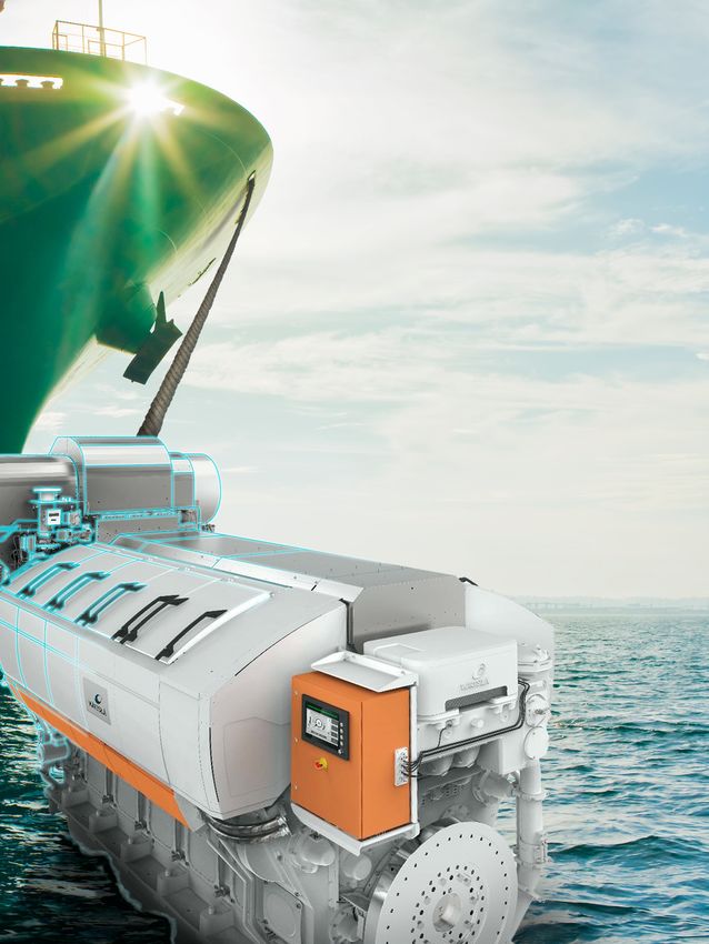
Marine | Engineer Innovation

The maritime industry is one of the          The Wärtsilä 31 (W31) is a medium
mainstays of the global economy:             speed 4-stroke engine, designed for use
around 90 percent of the world’s trade       as either a main propulsion engine or
involves shipping, while the cruise and      an auxiliary engine. It can run as either
leisure industry is a growing revenue        a diesel, dual fuel or spark-ignited gas
generating stream across the globe.          engine. Development took five years,
Shipping is recognized as the most           starting in 2010, and Lars Ola and his
efficient form of commercial transport,      team were involved from the earliest
with the lowest CO2 emissions per            part of the engine design process. “We
tonne of cargo transported. The              knew our customer requirements from
enormous scale of the industry,              internal stakeholders, so we aimed to
however, means that it is still a            make a new engine to replace existing
significant contributor to the world’s       models but also be of benefit to new
CO2 emissions. The maritime industry is      customers”. The new design had to be
working hard to reduce its                   fuel efficient and meet all regulatory
environmental impact, with new, stricter     requirements. Wärtsilä also decided to
emission regulations coming into force       use a modular design, making it easier
in the coming years. Ship manufacturers      to change parts and assemblies: small
and engine designers need to respond         size modular engines have been in use
to these new rules and come up with          for a while, but no other engine of this
new, efficient designs quickly. And if you   size uses this kind of modular
want to reduce emissions then you start      approach.
with the source: the engine. Wärtsilä is
one of the biggest ship engine               Contribution of Simulation to engine
manufacturers and servicing agents in        design
the world - one in three ships. To stay      The Thermofluids & Simulations team
ahead of the competition they are            have used Simcenter software as part of
always innovating and developing. They       the engine design process since the
are committed to sustainability, with an     year 1999. Simcenter is used for both
overriding focus on ensuring                 computational fluid dynamics (CFD) and
profitability, providing environmentally     internal combustion (ICE) analyses. This
sound products and services while            was the first time however that CFD had
ensuring responsible business conduct.       been used so early in the design
                                             process: Lars Ola and his team ran initial
The Wärtsilä 31 diesel engine, released      simulations on potential designs even
in 2015, has been awarded the accolade       before the W31 3D Computer aided
of Most Efficient Diesel Engine by the       design (CAD) was completed. “We
Guinness book of world records. This is      looked at potential new system features
due to its diesel fuel consumption being     for combustion on existing engine
as low as 165 g/kWh, far lower than any      geometries. This gave us great freedom
other 4-stroke diesel engine currently       to try new things, as we could make
available on the market. Its exceptional     mistakes virtually rather than creating
fuel efficiency is made possible through     expensive prototypes”.
the use of new technologies, including
2-stage turbocharging, a high-pressure       The scope of the CFD contribution to
fuel injection system and adjustable         the project was not pre-defined. As the
valve actuation, with a next-generation      engine design evolved, CFD was used
engine control system. We sat down           for analysis of more parts of the engine,
with Lars Ola Liavåg, manager of the         including the complete charge air and
Thermofluids & Simulations team to           exhaust manifold systems. Looking at
find out more about this amazing             the finished engine, Lars Ola comments
engine, and how multidisciplinary            “You can go round the whole engine
design simulation using Simcenter has        and point out here we have simulated,
helped Wärtsilä to create this innovative    here we have simulated, here we have
engine.                                      simulated. CFD helped make many

                                                                                     5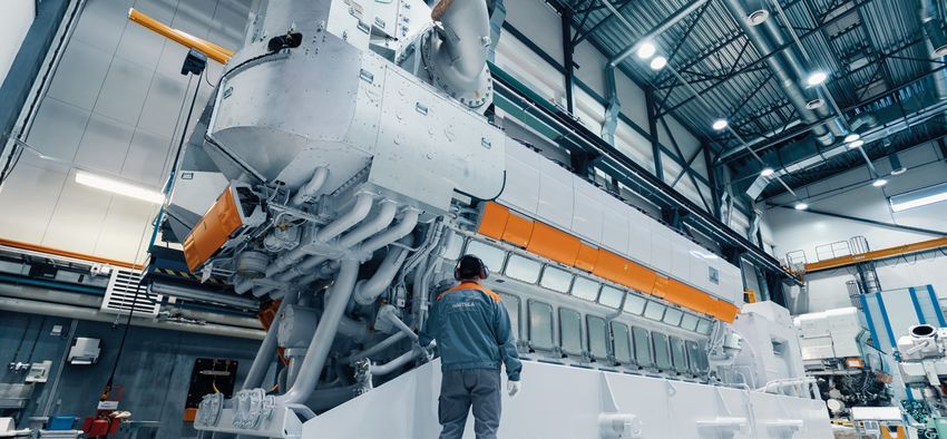
Engineer Innovation | Marine
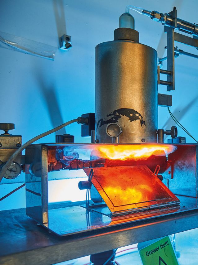
Figure 1: The Wärtsilä 31 engine holds the Guinness World Record for the most efficient 4-stroke diesel engine
The wide variety of physical models
available in Simcenter STAR-CCM+
meant that many different engine
components could be analyzed. For
example, the team simulated oil
splashing within moving engine
pistons, using the Volume of Fluid
(VOF) model for the oil and overset
meshes for the piston motion.
Conjugate heat transfer simulations
Figure 2: Simcenter STAR-CCM+ is being used to simulate transient gas dynamics in the
complete charge air manifold design provided thermal data which could be
mapped on to solid models for stress
analysis, and loose fluid/solid coupling
small modifications, and these add up was also used directly in Simcenter
to a significant impact on the final STAR-CCM+ to model the complete
engine design”. exhaust manifold. This approach
enabled thermal analysis of different
Lars Ola admits even he was surprised components such as bellows and
at how much they could simulate using fastening clamps.
SimcenterTM STAR-CCM+TM: “I thought it
was a joke when one of the guys The Thermofluids & Simulation team
proposed to model the complete charge also used Simcenter software for the
air manifold system with transient in-cylinder combustion analyses: these
fluctuations and all. Believe me, that is are vital to ensuring a safe, fuel efficient
one big system! engine. Having worked with in-cylinder
analysis for many years himself, Lars
But this is the kind of idea that comes Ola considers Simcenter to be a
out of using such an efficient software: powerful tool:
the case used 70 million cells but is not
even the biggest case we can run now”. “Thanks to the strong support and
Thermal data from the complete charge collaboration with experts at Siemens,
air system was mapped on to solid we can run a full engine cycle in one
models for stress analysis. As well as day with our power licensing.” For the
this the air cooler intake ducts were development of the Wärtsilä 31 engine,
redesigned, which improved flow the team performed over 660 gas
uniformity. combustion simulations and way more
6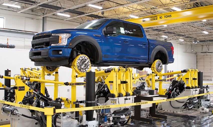
Marine | Engineer Innovation

than 1,200 diesel combustion
simulations. These helped us optimize
the piston geometries, fuel injector
specifications and operating parameters
for the engine.

This was the first time that a Wärtsilä
engine family had been developed in
both diesel, gas, and dual-fuel versions
already from the outset, and these
advanced CFD analyses helped ensure
the design was optimized for both
diesel and gas fuel operation. Inlet and
exhaust ports were also optimized using
CFD, and so were many critical
                                            Figure 3: Complex physics like oil splashing with moving engine piston require sophisticated high
components such as the prechambers          fidelity modeling approaches, here Volume of Fluid method on overset moving mesh
of the gas engine version.

Cross-company collaboration
While the Thermofluids & Simulation
team are the main users of CFD
simulation, Lars Ola notes that use is
becoming more widespread throughout
the company. Engine design engineers
are now using embedded CFD within
NX, their CAD tool, to analyze flow                                                                                          Temperature (C)
through engine components from the                              Velocity: Magnitude (m/s)

very first design. Lars Ola supports this   Figure 4: Fully embedded loose fluid/solid coupling approach for thermal analysis of e.g. the
CAE democratization: “Involving basic       exhaust manifold
CFD as part of the CAD design process
means we receive fewer bad designs
which we have to reject: it reduces the     now use Simcenter STAR-CCM+ to build
virtual scrap rate”. The Thermofluids &     some of their conjugate heat transfer
Simulation team also worked closely         models.
with the structural analysis team to
create a thermal management analysis        With this increased use of simulation
process based on conjugate heat             software, efficient use of computing
transfer (CHT) simulations and in-          resources is a priority. Wärtsilä have one
cylinder CFD. As part of this project,      of the biggest computer clusters in
also Finite Element (FE) engineers can      Finland: this capacity is used for both FE

                                                                                                                                               7
Engineer Innovation | Marine

                                                                                5º CA b TDC           20º CA a TDC
                                           DF combustion, gas mode

                               Figure 5: More than 660 Gas and 1200 Diesel combustion CFD simulations have been carried out
                               to find an optimum combustion chamber and injector configuration and ideal engine operating
                               conditions

                               Figure 6: CFD simulation of the prechamber, one of the critical components for the gas powered
                               engine

                               and CFD analysis. Simcenter STAR-                Lars Ola comments, “Our use of CFD
                               CCM+’s power licensing scheme means              meant we knew a lot better what to
                               the teams are not limited in their use of        expect before we started the engine in
                               parallel cores, allowing them to meet            the lab and allowed us to use our
                               their varying simulation needs. “The             testing capacity in a much smarter
                               power licensing was a quantum leap               way”.
                               forward in capability for us, as it
                               allowed us to ride the wave of hardware          This way of working, with the use
                               capacity improvement. We can use our             of simulation through ideation,
                               computing resources to their maximum             concept and detailed design stages,
                               capacity and run full engine cycle               meant that the final engine has
                               simulations in just one day”.                    exceeded the planned performance
                                                                                targets from the very first version.
                               Final design testing                             Instead of a prototype stage lasting
                               Wärtsilä’s use of CFD from early in the          several years, with subsequent release
                               design process not only improved the             stages to fix later problems, the
                               design but also reduced the amount of            Wärtsilä 31 has already been optimized
                               engine rig testing required.                     and rigorously tested via virtual
                                                                                validation. Looking back on the
                               As a big bore engine can burn several            changes in the development process
                               tonnes of heavy fuel per hour, reducing          over the years, Lars Ola comments that
                               the physical testing saves both time and         “It is the way of working that is the real
                               energy, as well as reducing costs. As            revolution. We are using the tools

8
Marine | Engineer Innovation

Figure 8: Expensive test rig time can be significantly reduced thanks to the use of simulation
through the complete development cycle from ideation, concept and detailed design stages

available to us to create the best                 optimized to comply with all existing
possible product in a way that was not             and anticipated emission regulations
possible twenty years ago. We would                and has an expected lifetime of 40
not have been able to work this way                years.
without the modern CAE tools and
high performance computing (HPC)                   From this discussion, it is clear to see
systems”.                                          that CFD simulation is embedded in the
                                                   design process at Wärtsilä and has been
Powering the ships of the future                   instrumental in helping them to bring
All these different contributions from             this new engine to market in just five
CFD to the design process can be seen              years. The Wärtsilä 31 engine was
in efficiency of the final engine,                 officially unveiled at Nor-shipping 2015
contributing to the reduction in CO2               and Wärtsilä have already fulfilled
emissions compared to equivalent                   orders for both gas and diesel modes.
engines. Diesel fuel consumption can               As ship owners look to meet efficiency
run as low as 165 g/kWh, while the total           regulations, Wärtsilä are meeting that
hydrocarbon emissions of the gas                   market demand, aided by their use of
engine have been reduced by up to                  Simcenter and digital design. n
50 percent. The engine has been

                                                                                                       Figure 7: Temperature
                                                                                                       distribution on the
                                                                                                       complete engine block
                                                                                                       stemming from solid/
                                                                                                       liquid CHT simulations

                                                                                                                            9
Engineer Innovation | The Digital Twin

                                                  Apollo 13: the first digital twin
This view of the severely damaged Apollo 13
                                                  How digital twin technology helped NASA
Service Module was photographed from the
Lunar Module/Command Module following
                                                  enact the greatest rescue mission in
the jettison of the Service Module. As seen
here, an entire panel of the Service Module
                                                  history
was blown away by the apparent explosion
of oxygen tank number two located in Sector
                                                  By Stephen Ferguson, Siemens Digital Industries Software
4 of the Service Module. Image credit: NASA

                                              50 years ago, on April 14th, 1970, 55 hours
                                              and 55 minutes after launch, Apollo 13        55:55:20
                                              suffered a catastrophic explosion in its      Commander Jim Lovell:
                                              service module.                               I believe we've had a problem here.
                                              Although the astronauts did not instantly
                                              recognize the severity of the problem (or     55:55:28
                                              even that fact that there had been an         CAPCOM
                                              explosion). The damage this caused left       This is Houston. Say again, please.
                                              the Apollo 13 venting oxygen, with a
                                              critically damaged main engine, and           55:55:35
Apollo 13 Mission Insignia - the
motto reads “from the moon,                   failing life support systems 200,000 miles    Commander Jim Lovell:
science”. Image Credit NASA                   away from earth. In the entire history of     Houston, we've had a problem. We've
                                              the human species, no-one had ever been       had a MAIN B BUS UNDERVOLT.
                                              in trouble so far from home.
                                                                                            55:55:42
                                              This article is not the story of the Apollo   CAPCOM
                                              13 mission, plenty of others have done a      Roger. MAIN B UNDERVOLT.
                                              much better job of telling that tale.
                                              Instead this is the untold story of the       55:55:57
                                              digital twins that helped Mission Control     CAPCOM
                                              to overcome incredible odds and bring         Okay, standby, 13. We're looking at it.
                                              the astronauts home safely.

10
The Digital Twin | Engineer Innovation
How do you look at, and solve, the
problem of a failing physical asset that
is 200,000 miles away and outside
direct human intervention (other than
from the three astronauts trapped
inside who could not even see the
damage that had been caused by the
explosion)?
In the first moments after the
explosion, Mission Control struggled
just to keep the astronauts alive,
conscious that any wrong decision
might cause further terminal damage to
the fragile spacecraft. Mission Control
in Houston worked around the clock. To
bring the astronauts home, they would
have to work out how to maneuver and
navigate a badly damaged spacecraft
operating in an unusual configuration
that was well outside of its design
envelope. They would have to find
innovative ways of conserving power,
oxygen and water, while keeping
astronauts and spacecraft systems alive. Apollo Simulators at Mission Control in Houston. The Lunar Module Simulator is in the
foreground in green, the Command Module Simulator is at the rear of the photo in brown.
And finally, they would have to work Image credit: NASA
out how to restart a command module
that was never designed to be switched
off in space. success of the Apollo program, and how
50 years ago their flexibility and
Behind the scenes at NASA there were adaptability helped to bring three
15 simulators that were used to train American astronauts safely home from
astronauts and mission controllers in deep space.
every aspect of the mission, including
multiple failure scenarios (some of Of course, by itself a simulator is not a
which came in useful in averting digital twin. What sets the Apollo 13
disaster in both Apollo 11 and 13). In his mission apart as probably the first use
autobiography, Gene Kranz describes of digital twin, is the way that NASA
that Apollo simulators as “some of the mission controllers were able to rapidly
most complex technology of the entire adapt and modify the simulations, to
space program: the only real things in match conditions on the real-life
the simulation training were the crew, crippled spacecraft, so that they could
cockpit, and the mission control research, reject, and perfect the
consoles, everything else was make- strategies required to bring the
believe created by a bunch of astronauts home.
computers, lots of formulas, and skilled
technicians”. There were three But before we explore the critical role
command module simulators, one in these prototype “digital twins” played in
Houston (where Mission Control was the rescue of Apollo 13, it’s worth
located), and two in Cape Kennedy (the examining how these simulators helped
launch site). There were also two lunar prevent disaster for both Apollo 11 and
module simulators, one at each 13 even before the launch of either
location. mission.
Although they obviously weren’t called Use before launch
that at the time, my contention is that If you listen to the audio recordings of
these simulators were perhaps the first the flight controller loops immediately
real example of “digital twins”. I’ll after the explosion, what strikes you
explain in this article how these high- most is the sense of controlled calm
fidelity simulators and their associated that is maintained throughout the
computer systems were crucial to the incident. No-one panics, no-one loses
11Engineer Innovation | The Digital Twin
Apollo Command Module Mission Simulator showing Apollo 13 prime crew member Ken Mattingly in training. Mattingly was bumped from the
crew a few days before launch because of exposure to the measles. Image credit: NASA
control, all that you can hear is calm the crew and mission control these
reasoned decision making in the face of include “Go, No-go” decisions at critical
a terrible and potentially tragic stages of the spaceflight, and how
unfolding situation. decisions would be made in a crisis.
This is because of the flight controllers, The various simulators were controlled by
and the Apollo 13 crew, were well- a network of digital computers, up to ten
rehearsed through simulation. Before of them, which could be networked
launch, simulators were used to define, together to simulate a single large
test, and refine “mission rules”, the problem. There were four computers for
instructions that determined the actions the command module simulator, and
of mission controllers and astronauts in three for the lunar module simulator. The
critical mission situations. Among the computers could communicate using 256
many simulators, the command module kilobytes words of common memory,
simulators and lunar module simulators where information needed throughout
occupied 80 percent of the Apollo the simulation could be stored.
training time of 29,967 hours.
There are at least two examples of
Flight director, Gene Kranz’s, White simulated scenarios that directly
Mission Control Team (one of three) had influenced the successful resolution of
11 days of simulation training to prepare problems on the actual missions
for the landing of Apollo 11, seven of (although there are likely hundreds
those with the actual crew, and four with more).
simulated astronauts. As well as training
both teams, the purpose of the sessions In the final simulation of the Apollo 11
was to define a set of “mission rules” that mission, controllers wrongly aborted
would define any actions taken by both during the final stages of lunar landing
12The Digital Twin | Engineer Innovation
when the guidance computer issued an
“1201 alarm code" that the controllers
had never seen before. After quickly
determining that the error was
indicating a computer overload that
meant it might not be keeping up with
its computing tasks, mission control
called for the abort. This was the wrong
decision, after conferring with the
Massachusetts Institute of Technology
(MIT) team that programmed the
computer, guidance officer (GUIDO),
Steve Bales later concluded that an
“1201 code” was a warning rather than a
critical error and rewrote the mission
rules just nine days before the eventual
landing. If the final simulation hadn’t
prompted him to do that, it’s likely the
actual Apollo 11 landing, the final
minutes of which were plagued by a
Mission Control in Houston, moments before the explosion that would plunge the Apollo 13
series of 1201 and similar 1202 alarms,
mission into crisis. In the middle of the shot is White Team Leader, Flight Director Gene Kranz,
would also have been aborted. The whose team was responsible for defining the strategies to bring the crippled spacecraft safely
Eagle would not have landed. home. Image credit: NASA
During preparations for Apollo 10,
mission controllers were tested in a Internet of Things”, NASA did use
simulation which involved the failure of state-of-the-art telecommunications
the spacecraft’s fuel cells as it technology to stay in touch with its
approached lunar orbit, a scenario spacecraft. That data was ultimately
which is staggeringly similar to the used to modify the simulators in order
Apollo 13 explosion. Controllers tried to to reflect the condition of the crippled
evacuate the astronauts into the lunar spacecraft.
module, using it as a “life raft”, but did
not manage to get it powered up in In the audio transcripts of the Apollo 13
time, killing the virtual crew. Although flight controller loops, most of the
many NASA insiders rejected the immediate discussion is about
multiple failures of that scenario as maintaining data connections with the
“unrealistic” it inspired the controllers spacecraft (such as executing roll
involved to develop procedures that maneuvers to better align the main
would allow the lunar module to be antenna array with ground tracking).
used as a lifeboat, even with a crippled One of the unsung heroes of the
command module. incident was the Integrated
Communications Officer (INCO), Gary
Although the simulators did not play a Scott who calmly kept the data
key role in the design of the spacecraft, communications stream running, while
they did play an essential role in almost everything else was falling
defining its operating parameters. This apart.
illustrates one of the key purposes of
the digital twin: to test the asset, and its Although for some people the Apollo 13
systems and procedures, over a wide story begins with commander Jim
range of possible operating conditions. Lovell’s ominous “Houston we have a
problem” announcement (actually
Connected twins “Houston we’ve had a problem”),
Most modern digital twins involve a mission control was immediately aware
remote physical asset which is that something had gone wrong
connected to the digital model through through telemetry even before Lovell’s
a continuous stream of data. This voice report (delayed by 3 seconds by
connection is used to update the the transmission distance), as the
computer models in response to guidance officer calmly announces
changes in the real-life object. Although “We've had a hardware restart. I don't
Apollo 13 obviously didn’t use “the know what it was”, and then seconds
13Engineer Innovation | The Digital Twin
The Apollo spacecraft in docked configuration. The Lunar Module, on the left of the picture, was designed to take two men to the moon’s surface
and back before being jettisoned. For the Apollo 13 mission it provided a life raft and engine to bring the astronauts safely back to earth following
an explosion in the service module. Image credit: NASA
afterward the Electrical, environmental, which was not instantly recognized as
and consumables manager (EECOM) an explosion, they also had to rely on
controller announces, “we've got some the same telemetry as was being
instrumentation funnies, let me add transmitted back to mission control. In
them up...we may have had an the early stages of the crisis Kranz and
instrumentation problem”. the crew switch in and out different
systems to try and work out what is
In the first 15 minutes after the working and what is broken.
explosion, flight director Gene Kranz
became wrongly convinced that the Although the Apollo era data
problems that they were observing communications are crude by modern
were a symptom of communication standards - they do highlight a common
problems caused by an antenna glitch problem with modern digital twins:
that they had been trying to resolve acquiring real-time data is one thing but
earlier, and which had been a frequent processing that data into a form that
problem in the previous Apollo can be easily used to make real-time
missions. In his autobiography, Kranz decisions remains a challenge.
berates himself for this and wasting
critical time in pursuing the wrong Even considering these limitations,
scenario, although to any outsider he mission control was able to quickly and
seems to be following a calm and accurately diagnose the problem and
rational decision-making process during evacuate the astronauts into the lunar
a rapidly unfolding crisis. module before their oxygen supplies
failed. They also made the sensible
Kranz says “In mission control, you can’t decision that the service module engine
see, smell, or touch a crisis except was damaged beyond repair. They were
through telemetry and the crew’s voice also able to use that data to modify
reports”. The crew trapped inside the their simulators to reflect the condition
command module could not see the of the physical asset, another key
damage, and other than the loud thud, quality of the digital twin.
14The Digital Twin | Engineer Innovation
Apollo 13 Mission Profile drawn to scale. Image Credit Andrew Buck.
Digital twin to the rescue being modified to reflect the unusual
NASA faced many problems that all spacecraft configuration, which
needed to be solved in order to bring involved reprogramming the
the crew safely home, several of them mainframes with information about the
solved only with the extensive use of new spacecraft mass, center-of-gravity
the simulator digital twins. and engine thrust. Working together
with the lunar module manufacturer,
One significant recurring problem was Northrop Grumman, the simulation
that of maneuvering the spacecraft, team quickly worked out a new
which was never designed to operate procedure in which the ship could be
using the lunar module with crippled stabilized using autopilot and deploying
service and command modules attached the landing gear to get it out of the way
for the whole return journey. With the of the descent engine. It worked and
guidance computer powered down to the crew were successfully able to
save energy, the crew had to manually perform the free return burn, greatly
align the spacecraft precisely to make increasing their confidence.
three separate engine burns which
required keeping the spacecraft on a free A similar problem occurred two hours
return trajectory to earth. In normal after Apollo 13’s closest approach to the
operation these maneuvers were moon (the so called aspericynthion or
performed by the onboard computer, but PC for short), intended to speed up the
in this unusual configuration much of return voyage by 12 hours, and bring
the work had to be performed manually. their return just within the lifetime of
With limited fuel on board, any mistake their battery supplies. The problem this
could have been terminal, and left the time was that the lunar module’s
vessel on a wrong trajectory. guidance systems had been turned off
to conserve power, forcing the
The early signs were not promising, as astronauts to manually align the
the crew struggled to control the spacecraft using only visual cues.
spacecraft “Why the hell are we Ordinarily the crew could have
maneuvering like this, are we still navigated using the stars as a backup,
venting” exclaimed a frustrated Jim but the large amount of debris
Lovell at one stage. surrounding the crippled spacecraft
made it impossible for the astronauts to
Mission Control immediately dispatched identify any constellations. In
the backup crew to practice the desperation, NASA once again turned to
maneuvers on the simulators that were the simulators. After hours of trial and
15Engineer Innovation | The Digital Twin
70 amperes, however which would have
exhausted the limited battery supplies.
To conserve precious power supplies,
mission control had shut-down non-
essential systems (including crew
heaters) to reduce the load to less than
12 amps (less than a domestic vacuum
cleaner). But even still, as the time
approached to power-up the command
module less than two hours of power
remained.
Behind the scenes EECOM, John Aaron
worked around the clock to define a
minimal power-up sequence, which
everyone hoped would awake the
command module before re-entry with
the trickle of power left in the batteries.
The exhausted and frozen crew were
understandably anxious about correctly
working their way through a long and
complicated procedure that involved
operating hundreds of switches in the
correct order. Any mistake, any
omission, would likely prove fatal, as
turning the wrong system on would
instantly deplete the small amount of
Apollo 13 flight directors celebrate the successful splashdown and recovery of the Apollo 13 crew. remaining power. Astronaut, Ken
From the left are Gerry Griffin, giving thumbs up, Gene Kranz and Glynn Lunney. Mattingly (who was bumped from the
Credits: NASA Apollo 13 crew a few days before
launch), sealed himself in a dark
error, the simulator team came up with command module simulator to rehearse
the ad-hoc process to align the tiny and refine the switch on sequence
window of the lunar module with a before it was broadcast to the crew.
quadrant of the sun. Before making the
complicated alignment maneuver Is that really a digital twin?
commander, Jim Lovell sought repeated I don’t think it’s much of a spoiler to tell
assurance from mission control: “Had you that, thanks to the round the clock
the backup crew configured the work of hundreds of NASA engineers
simulator properly with the lunar and controllers, the three astronauts
module in docked configuration? Had were returned safely home. What could
they had any trouble performing the have been NASA’s greatest disaster
maneuver?”. He needn’t have worried. turned into its greatest triumph.
Using the rapidly assembled procedure Although the Apollo 13 mission
Lovell managed to align the spacecraft happened 32 years before the coining
with the one-degree margin of error of the term “digital twin”, I do think that
required to keep it on course. it remains one of the best real-life
examples of a digital twin in action. I
The final problem was that in order to don’t think the astronauts would have
use the lunar module as a life-raft, the made it safely home without it.
astronauts had to power down the
command module, which they would Here are the characteristics of the
ultimately return to for reentry. Apollo simulators that I think defines
However, the command module was them as perfect examples of a digital
only ever designed to be powered-up twin in action:
on the launch pad, a complex process
that took over two days, and no • Physical: Digital twins are most useful
procedures existed for restarting in when they relate to physical assets
deep space, with almost exhausted that are (at least temporarily) out of
power supplies. Under normal reach of direct human intervention.
operation the lunar module drew about Even though there were three
16The Digital Twin | Engineer Innovation
Apollo 13 crew arrive on the prime recovery ship U.S.S. Iwo Jima following the ocean landing and rescue in the South Pacific. Leaving the helicopter
are (from left) Fred Haise, mission Commander James Lovell and John Swigert. Credit: NASA
astronauts on-board, Apollo 13 is a modern digital twins need to be
perfect example of this. based around a single “grand unified
• Connected: Digital twins require model” that predicts every aspect
constant feedback of data from of the physical device is also false.
the physical asset that can be used Contemporary digital twins consist of
to update their condition, and multiple interacting models that can
then is used to inform engineering be combined to account for different
decisions: a key requirement of a aspects of performance.
digital twin. Modern digital twins • Responsive: The events of Apollo 13
typically use “the Internet of Things” played out over just 3 and half days,
to achieve this aim, NASA achieved during which incredible amount
the same purpose with advanced of adaptation and re-engineering
telecommunications which included occurred. I doubt whether many
two-way data transfer. contemporary digital twins could
• Adaptable: Digital twins need to be have be deployed so quickly after
flexible enough to react to changes critical damage to their physical asset.
in the physical asset. NASA were
able to reconfigure their simulators Finally, if you are wondering what
in a matter of hours to reflect a Siemens had to do with all of this: we
configuration that had never been made the incandescent lamps that
envisaged during their design and use illuminated the instrument panels of
those simulations to provide critical Apollo 13 with magical green light.
information to the crew. Apparently, the lamps consumed almost
• Threaded: There wasn’t a single no electricity, which is useful when you
“digital twin” for the Apollo program; are stuck on a broken spacecraft
NASA used 15 different simulators 200,000 miles from home. n
to master the various aspects of
the mission. The conception that
17Engineer Innovation | Plant & Process
Hager Group
Simcenter FLOEFD: The Swiss army knife
for the trunking system design team
By Stefan Spies (head of tool development), Bernd Trapp
(tool design engineer), Thomas Szabó (product manager)
“ The The complex trunking structures are made
of plastic materials, such as PVC, and
produced in a continuous manufacturing
standards. The location in Heltersberg
employs 740 employees and was founded
in 1957.
requirements process on modern extrusion lines. In
addition to the detailed adjustment of the Trunking systems bring electricity and
on our tools in individual system components, a multiple
strand extrusion tool is a core element of
these complex systems. The multiple
data efficiently to varied locations within
organizations resulting in the requirement
for trunking solutions to be highly flexible
terms of strand design ensures efficient, high
output quantity. Modern design
to serve production, laboratories, practices
and office spaces (Figure 2).
quality, output technologies, product complexity, material
and color variations have lead the need to Hager Group and Siemens have been
an increase in the number of special tools working together since the 1960s and
capacity and that are developed and put into operation
every year.
today, Hager’s varied product portfolio
includes a wide range of systems from
cycle times are The Hager Group, is a family owned
security systems to smart home devices
and charging stations for electic vehicles.
leading supplier of solutions and services
continuously for electrical installations in residential,
commercial and industrial buildings,
Unlimited material, color and size
variations
increasing.” employs around 11,500 employees. The
sub-division Tehalit GmbH based in
One of the strengths of the Hager Group’s
trunking division is their ability to
Heltersberg, Germany, has been a part of manufacture and supply extrusion lines
Stefan Spies,
the Hager Group since 1996 and is the using a very high proportion of in-house
head of tool development
creator and European market leader for manufacturing and development. Even
trunking systems with high flexibility for though the external appearance of
site and installation conditions, while trunking systems has changed only
maintaining high safety and reliability slightly in recent years, the geometric and
18Plant & Process | Engineer Innovation
system complexity continued to increase,
with size differences ranging from 4 x 4
millimeters (mm) to 380 x 120 mm (Figure
3). This is in addition to the number of
material and color variants that are also
constantly being created.
Unique competitive advantage through
complex multiple strand tools
The complexity, functional requirements
and quality demands on the extrusion tool
increases, while cycle times shorten. In
2008 approximately 30 tools per year
were developed, today there are more
than 50 tools per year. Each tool is a
special-purpose tool. Multiple four-strand
tools were successfully put into operation
in a shorter time with the help of
Simcenter™ FLOEFD™ and provide a
unique competitive advantage (Figure 4).
100 kilometers (km) of cable trunking is
manufactured per day with no waste as
Figure 1: Extrusion tool and calibration
the material is used again and again. One
of the main targets is to achieve a uniform
melt distribution at the tool outlet to the technical support team, the
maintain the product quality (Figure 5). continuous further development of the
software and regular workshops, the
The Hager Group design engineers are knowledge was deepened even further.
responsible for the entire development Besides the mold and tool design, the
process of their tools, starting from the profile calibration as well as the layout of
basic digital concept up to the the cooling line are part of the
commissioning and final approval at the simulations.
point where the tool is put into operation
at the extrusion line. It is important to be The existing experience of the Hager
able to work without any additional engineers in extrusion tool design has
dependencies from others or external been extended over the years with further
interfaces and thereby ensure an optimal theoretical know-how, experience and
development and design process. knowledge about the material properties
or physical conditions of non-Newtonian
Hager’s approach to frontload their media and corresponding viscosity
simulations models. In addition, deeper insights were
Hager Group engineers have been using gained into the shear rate range that the
Simcenter FLOEFD in their development new tools must cover. PVC, including
process since 2008 and were able to use multiple additives, is one of the most
the results created in their initial training difficult material for the determination of
session resulting in a fast and productive the specific properties. At the same time,
implementation. With the assistance of the material is often processed at the
Figure 2: High flexible trunking system tehalit.BR65 Figure 3: Size differences
19Engineer Innovation | Plant & Process
process. The responsible design engineer
can carry out and evaluate the simulation
independently.
“While in 2008 we needed several days for
the calculation, the flow analysis for our
extrusion dies are already completed after
a few hours and we then calculate models
with up to 15 million cells, explains Bernd
Trapp, design engineer for extrusion tools.
Figure 4a: Single strand tool Figure 4b: Multi strand tool Each extrusion tool is unique, and is put
into operation and adapted directly on the
machine after development. For each
project, a comparison is made between
the simulation and the flow-part during
commissioning at the extrusion line, so
that findings are continuously
incorporated into the simulation process.
Figure 6 shows the first flow part sample
between the extrusion tool and the
calibration unit. The red areas in the top
left image were identified and optimized
with the help of the simulation. The
bottom image shows the optimized
Figure 5: Optimized melt distribution in the right image (red areas). configuration, which is appropriate to be
passed through the calibration unit.
temperature limits in the complex tool,
which is impossible to be estimated Extension of the application areas since
without simulation. In particular, through 2008
the complete embedding of Simcenter The application areas of Simcenter
FLOEFD in PTC Creo, in combination with FLOEFD are constantly extended. Initially,
the automatic mesh generation, more and the flow behavior in the extrusion dies
faster optimization runs were made was optimized (Figure 7). In this case, the
possible. flow velocity, pressure, viscosity, shear
rate, temperature, shear stress, and
Extremely shortened development pressure distribution in the die were
cycles with Simcenter FLOEFD optimized.
The extrusion tool development cycles
were shortened dramatically and the use Then the thermal design of the calibration
of Simcenter FLOEFD made it possible to tools was carried out with special
integrate the computational fluid consideration of the material properties.
dynamics (CFD) simulation into the design (Figure 7 a, b). Followed by cooling
Figure 6: Simulation and flow-part samples which were taken during the commissioning
20Plant & Process | Engineer Innovation
Figures 7 a, b: Extrusion die flow behavior analyses
Figure 8a: Profile calibration Figure 8b: Cooling behavior of the profile Figure 9: Cooling optimization
optimization for the calibrating tool are becoming more complex. With
(Figure 8). Particle studies were then Simcenter FLOEFD we cope with these
carried out, while extracting systems at challenges very well.” explains Stefan
the extrusion line were analyzed (Figure Spies, head of tool development.
9). Finally the results are transferred to
additional simulations, such as structural “Our approach from 2008, was that each
analyses. Since 2008, Simcenter FLOEFD is extrusion tool should optimized by the
the tool of choice for many application responsible design engineer with
areas, instead of using different tools for simulation during the design process, this
each area. has become a successful reality.” n
“When we started, we mainly focused on
the flow velocity and shear stress of the
non-Newtonian media. Meanwhile, the
software has become also the tool of
choice for many different applications.
Our team uses Simcenter FLOEFD as a
Swiss Army Knife around the tool
development.”
“Regarding the flow conditions, our tools
are now optimally designed from the very
beginning through simulation. In
combination with our experience around
shrinkage and contraction we can design
our ideal tools.” explains Bernd Trapp.
“Today, three to ten loops are simulated in
advance for each tool, and modifications
in the ramp-up process are also
considered. The requirements on our tools
in terms of quality, output capacity and
cycle times are continuously increasing. Figure 10: Team Tool Design: Stefan Spies, Sascha Rollwa, Michael Riehmer, Bernd Trapp, Peter
At the same time, our trunking systems Wander, Tobias Seewald, Björn Schmitt
21Engineer Innovation | Automotive & Transportation
HASETRI keep the
wheels of innovation
turning
Preparing for an electrical vehicle future
with Siemens Digital Industries Software
testing solutions
Driving research and development in through mechanical, chemical, and
rubber technology analytical testing, simulation,
The Hari Shankar Singhania Elastomer & performance evaluation and product
Tyre Research Institute (HASETRI) in India certification.
is dedicated to the independent research
and development (R&D) of new and Tire importance
improved technologies for elastomers While engines and transmissions are
and tires. HASETRI’s primary goal is to believed to be a vehicle’s most critical
foster the development and evolution of components, the development of the tire
new technologies for the rubber and revolutionized road transportation.
allied industries. HASETRI’s facilities host three rubber
trees, which grow under the care of
“Excellence comes not from words or gardeners. Today, the institutes explore
procedures. It comes from an urge to new ways to manufacture tires, use
strive and deliver the best,” says Hari innovative materials and pioneer
Shankar Singhania, founder, HASETRI. “A manufacturing methods.
mindset that says, ‘When it is good
enough, improve it’ is a way of thinking HASETRI’s research includes the
that comes only from a power within.” development and testing of new
materials, new aggregation methods,
Established in 1991 as an independent innovative shapes and designs. Each
research and testing laboratory, HASETRI sample is tested using sophisticated
broadens the scope of material and tire laboratory equipment to predict the
research to make products that meet product’s performance in real-life
unparalleled standards in quality and conditions that include structural
performance. They accomplish this durability, abrasion (wear), etc.
22Automotive & Transportation | Engineer Innovation
“We stand at a crossroads today,” says Dr.
Rabindra Mukhopadhyay, director and “ We are confident that our
existing and future expansion
chief executive, HASETRI. “Resources on
earth are limited and we need to re-
invent mobility and develop more
sustainable means of transportation,
without which our existence is plans would be well supported
by Siemens.”
threatened. With our advanced research
on tire technology, we strive to
contribute to a better, more sustainable
world and economy.” Dr. Prasenjit Ghosh
Principal Scientist
Electrified vehicles require different HASETRI
tire characteristics
HASETRI also assesses the acoustic percent, which boosts instant torque
properties of tire materials and designs. generations in these vehicles and
This is crucial as government and increases the demand on the tires.
regulatory institutions continue to
impose stricter limitations on a vehicle’s To design tires with high noise levels at
acceptable noise levels, making the tire’s low vehicle speeds and low noise levels
noise performance critical. Tire noise, or at high vehicle speeds, the HASETRI lab
the sound produced by the friction of features extensive noise and vibration
tires on the road surface, is one assessment and testing capabilities.
contributor to a vehicle’s noise level. Lingineni Madhav is a test engineer in
Unlike internal combustion engine (ICE) HASETRI’s Tire Mechanics Group, which
cars, where the engine masks road deals with noise, vibration, harshness,
noise, the road noise from electric cars (NVH) and handling properties of tires
becomes more apparent since electric and related products. As a test engineer,
cars, of course, do not feature a loud Madhav ensures the smooth operation
combustion engine. In addition, the of different tests as per various national
battery in hybrid and electrical vehicles and international standards. He also
increases vehicle weight by 10 to 20 develops new test methods to further
23Engineer Innovation | Automotive & Transportation
“Simcenter testing solutions have
expanded our existing tools and skills set
to explore certain aspects of noise and
vibration testing,” says Madhav.
“Simcenter tools have been critical in
reducing the time needed for data
acquisition and data processing. Another
benefit Simcenter testing solutions
provide is the ability to rapidly access
different areas and domains during the
testing process. The support and
assistance from the Simcenter technical
team to resolve hardware-related and
technical and software-related queries
have been extremely valuable.”
Madhav continues, “The tests we
conduct are important considering
regulatory requirements, original
enhance the lab’s capabilities and carry specification (OE) specifications, and
out noise, vibration, and harshness benchmarking. They are also vital as we
(NVH) studies, which contribute to strive to continuously improve our
providing noise abatement solutions at understanding of the NVH domain and
both the components and vehicle levels. move in a direction to contribute to NVH
solutions both at the national and
Through the use of Siemens Digital international levels.”
Industries Software solutions
Simcenter™ Testlab™ software and Sound quality is an important criterion
Simcenter SCADAS™ hardware, the for the automobile industry. Moreover,
HASETRI tire mechanics department new drive and fuel concepts, tightened
carries out various NVH-related tests, ecological specifications, increase of
such as noise level measurements at vehicle classes and increasing
constant speed, speed-sweep tests on diversification, challenge the acoustic
the tire test rig located in a semi- engineers trying to create and preserve a
anechoic chamber, in-cabin and external pleasant cabin. Regulatory bodies are
noise measurements on the vehicle level becoming more stringent in regard to
at designated test tracks across India as NVH, especially in Europe. HASERTI
well as pass-by and coast-by noise believes it is important to provide
measurements. The department accurate and reliable information on
engineer also performs modal testing on critical NVH matters during the initial
tires and other relevant industrial design phase to meet these growing
components. requirements and standards.
24Automotive & Transportation | Engineer Innovation
HASETRI’s NVH section has ten highly their delivered testing projects. “We are
skilled engineers who are involved in able to educate our customers through
carrying out advanced NVH testing and training by experts from Siemens,” says
research. In 2014, HASETRI partnered Dr. Mukhopadhyay. “As a result of
with Siemens to establish an anechoic continuous interaction, we are able to
chamber with the latest technology, improve the quality, reliability and
including the chassis dyno in the very repeatability of our testing, the
early stages. HASETRI operates a cutting- interpretation of results and the testing
edge testing facility suitable for basic times.” n
testing to advanced engineering projects
that require a high-channel count and
special hardware (for example, multi- “ Another benefit Simcenter
reference transfer path analysis (TPA)
and road noise). The Simcenter Testlab
and Simcenter SCADAS hardware onsite
testing solutions provide is the
is scalable and easily used for both the
lab and mobile environments. HASERTI ability to rapidly access
plans to use Siemens solutions for future
projects. different areas and domains
“We are confident that our existing and
future expansion plans would be well during the testing process.”
supported by Siemens,” says Dr. Prasenjit
Lingineni Madhav
Ghosh, Principal Scientist, HASETRI.
Test Engineer
Tire Mechanics Group
Increased testing efficiency
HASETRI
Besides using versatile testing solutions
to provide customers with a wide range
of possible NVH tests, HASETRI focuses
on regular training of their engineers
and customers to improve the quality of
25Engineer Innovation | Interview
Interview
From Concept design to
production in 8 months
Spotlight on ElectraMeccanica: ElectraMeccanica’s
SOLO has been lauded as one of the coolest cars of
2020 by Forbes Magazine. They use an ever
expanding portfolio of tools including NX,
Teamcenter and Simcenter
Tell us a bit about your company.
Henry Reisner: our past CEO, Jerry Kroll
and I founded this company. I've known
Jerry for over 20 years. Jerry is a very
passionate environmentalist and even as
far as 15 years ago was interested in
electrification of transportation. At the
time I wasn’t sure that my customer base
was moving in that direction. But about
five or six years ago he brought the
concept of a single passenger urban
electric vehicle to me as something that
he was interested in exploring. I really
thought that this was an extremely
exciting and potentially very strong niche
that a small company could create. We
identified some potential IP to acquire What are the challenges facing your China. Our biggest challenge is to get
but upon visiting the company, we team? everybody to contribute and have the
discovered that there was nothing to Henry Reisner: As a startup, we've had channels of communication open so we
purchase. It was a disappointing turn of very good response from the financial can all give our best. Henry Reisner: As
events but on our flight home Jerry and I market through both private and our team of engineers grows and the
discussed whether it would be possible institutional investment backing. One of breadth of engineering partners grow,
to put together a team that could the things that we pride ourselves on is we all need to speak the same language
develop the IP and what kind of product not having a capital intensive approach and share the same data. That’s why we
we’d like to offer. This company is now at to this project. Therefore, we rely on rely on Siemens Digital Industries
the culmination of that journey. partners for both development and Software solutions. We are now in an
manufacturing. There are also expansion phase; therefore, we’re
What makes your product unique? geopolitical issues that have influenced adding more Siemens products as a part
Henry Reisner: Electric vehicles up to the way things are moving. No matter of our process to grow this company to
this point have been a fairly expensive how good the plan might be, things the next level. As we push on our
product. We have a purpose-built always come in from the side. I’m proud development, we can do a better job by
product that delivers everything that you to say that we are a committed, flexible having access to the same tools across
need for personal transportation on a and driven small team that is well the supply chain.
daily basis. It has a high level of supported by our executive team. So
functionality that meets the daily needs despite pandemics and political We have a strong, knowledgeable
of more than 70 percent of commuters. situations we will achieve our objective. partner in Maya HTT, an engineering
And we can do that at a sub $20,000 solution provider and Siemens Smart
price point. Bruce Gordon: And that How do you achieve those objectives? Certified Partner. Maya HTT’s team
makes it that much more accessible to a Bruce Gordon: We have a design team understands our corporate DNA and our
significantly wider population. Now that is scattered around the globe – specific needs. As a small, nimble team,
everybody can have a choice. Detroit, Los Angeles, Vancouver and we have a very different way of thinking
26You can also read