Guideline: Energy Utilisation - MANDELA MINING PRECINCT
←
→
Page content transcription
If your browser does not render page correctly, please read the page content below

MANDELA MINING PRECINCT
    MINDS FOR MINES

Guideline:
Energy Utilisation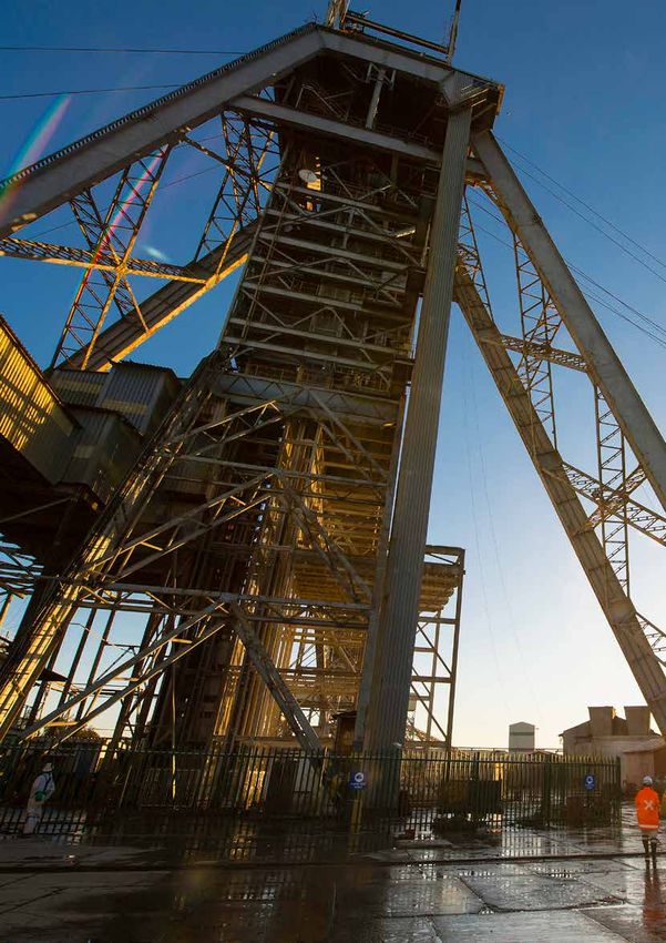
About the Mandela Mining Precinct

The Mandela Mining Precinct is a Public-Private Partnership between the Department of Science and
Innovation and the Minerals Council South Africa. The Precinct is jointly hosted by the Council for Scientific
and Industrial Research and the Minerals Council. The Mandela Mining Precinct is an initiative aimed at
revitalising mining research, development and Innovation in South Africa to ensure the sustainability of the
industry. This is achieved through the South African Mining Extraction, Research, Development and Innovation
(SAMERDI) strategy. The strategy comprises six research programmes:
1.   Longevity of Current Mining;
2.   Mechanised Mining Systems;
3.   Advanced Orebody Knowledge;
4.   Real-Time Information Management Systems;
5.   Successful Application of Technologies Centred Around People; and
6.   Test Mine.

This guideline was developed under the Mechanised Mining Systems research programme. The
programme is aimed at providing sustainable mechanised drill, blast and mechanical rock breaking
solutions in advancement towards atomised systems to facilitate achieving zero harm, whilst maintaining
and defending desired production rates at minimised costs, within the au and PGM mining industries.

ISBN number: 978-0-7988-5652-2

Contact details		    enquiries@mandelaminingprecinct.org.za
			www.mandelaminingprecinct.org.za
Editors			           Martin Pretorius (Mandela Mining Precinct) and Xiaohua Xia (University of Pretoria)
Contributing authors Dr Xianming Ye, Centre for New Energy Systems (CNES) at the University of
			                  Pretoria; and Peter Klein, Energy Centre at the Council for Scientific and Industrial
			Research (CSIR)
External Review      Roy Murley, Glencore; and Alex Fenn, Sibanye Stillwater
Executive Summary

In the context of rising electricity costs, compounded by nationwide electricity generation constraints, it
is important for the industry to explore a diversified energy supply through alternative self-generation
technologies such as renewables. This guideline is intended to assist the industry in selecting the most
feasible technologies suited to their needs.
Despite the effects of COVID19, 2020 has seen the highest levels of load shedding to date, with 1362 GWh of
energy shed. The IRP2019 has identified a short term capacity gap of 2000 MW up to 2022, which must be
filled in order to avoid future load shedding. This capacity gap will be further exacerbated if the performance
of the existing coal fleet does not recover from current levels. The mining sector can play a leading role
in the rapid role out of embedded generation and storage technologies to provide a customer response at
scale to this energy crisis. In recent communications the president has indicated that the government is
moving to create an enabling environment to allow customers to deploy embedded generation.
An overview of the proposed minimum technical specifications for the major components of a solar PV
plant is presented in this guideline, including applicable IEC and SANS standards that should be adhered
to, as well as recommendations to ensure plant performance. The guideline also provides an energy
planning methodology for conducting a techno-economic optimisation of an alternative energy generator.
The approach includes a demand side assessment, generator modelling and a least cost optimisation. A
case study is presented in this guideline for the optimisation of a solar PV plant and grid electricity for a
representative 30 MW mining profile.
As part of the latest Integrated Resource Plan 2019 (IRP2019) an allocation of 500 MW/yr from 2023 to 2030
has been provided for embedded generation, and an undetermined allocation between 2019 and 2022 to
reduce the short term capacity gap.
Despite the potential for cost savings through the deployment of alternative energy technologies, the high
levels of upfront costs, present a major hurdle that has to be overcome in the development of projects in
the mining sector. This guideline describes some financing approaches that could support mines pursuing
an alternative energy investment. The REIPPPP provides the best example of financing mechanisms for
the deployment of large scale renewable energy plants. Therefore an overview is provided on how projects
in BW1-4 achieved financial close. A description of applicable green finance funds from the DBSA and IDC
is also presented.

                                                                                                                  3
Table of Contents
Executive Summary                                                                      3
List of Figures                                                                        6
List of Tables		                                                                       7
List of Abbreviations                                                                  8

CHAPTER 1 INTRODUCTION AND METHODOLOGY                                                10
1.1 Introduction to POET                                                              11
1.2 Advantageous features of POET                                                     11
1.3 Applicability of POET                                                             13

CHAPTER 2 LITERATURE REVIEW                                                           14
2.1 Introduction                                                                      15
    2.1.1		 Renewable energy resources                                                15
    2.1.2		 Energy supply infrastructure                                              16

CHAPTER 3 ENERGY EFFICIENCY SPECIFICATIONS FOR SELECTED MINING CATEGORIES             19
3.1 Technical Specifications of a solar PV plant                                      20
    3.1.1		 Introduction                                                              20
    3.1.2		 Photovoltaic modules                                                      20
    3.1.3		 PV mounting structure – ground mounted (fixed tilt and tracking)          21
    3.1.4		 Inverters - technical requirements                                        22
    3.1.5		 Balance of plant - protection and control devices                         22
    3.1.6		 Balance of plant - lightning protection and earthing                      23
    3.1.7		 Balance of Plant –AC and DC cabling                                       23
    3.1.8		 Balance of Plant - meteorological station and monitoring                  23
3.2 Energy efficiency for belt conveyor systems                                       24
    3.2.1		 Introduction                                                              24
    3.2.2		 Conveyor belt system technology                                           24
    3.2.3		 Conveyor belt system specifications and maintenance                       27
    3.2.4		 Conveyor belt system Operation                                            28
3.3 Energy efficiency specifications for supercapacitors                              29
    3.3.1		 Supercapacitor technology                                                 29
    3.3.2		 Supercapacitor equipment specifications:                                  29
    3.3.3		 Supercapacitor operation:                                                 31
    3.3.4		 Supercapacitor performance:                                               32
    3.3.5		 Best available practice for supercapacitor                                32

CHAPTER 4 EEDSM + RENEWABLE INTEGRATION: COMMENTS ON A HOLISTIC OPTIMISATION          34
4.1 Energy modelling and optimization for alternative energy generators (renewable)   35
    4.1.1		 Introduction                                                              35
    4.1.2		 Demand assessment                                                         35
    4.1.3		 Generator modelling                                                       36

                                                                                           4
4.1.4		 System sizing and cost optimisation                                         36
    4.1.5		 Case Study                                                                  37
4.2 Energy modelling and optimization for demand-side management                        40
    4.2.1		 Methodology for performance optimization of EEDSM initiatives               40
    4.2.2		 Case study: optimal sizing of belt conveyor systems                         41
4.3 Battery-supercapacitor hybrid energy storage system application and optimisations   46

CHAPTER 5 ENERGY EFFICIENCY SPACE AND RENEWABLE REGULATION AND POLICIES IN SA           50
5.1 South Africa Integrated Resource Plan 2019                                          51
5.2 National tax incentive schemes                                                      53
    5.2.1		 Section 12I                                                                 54
    5.2.2		 Section 12L                                                                 56
    5.2.3		 Section 12B                                                                 57
5.3 Carbon tax and mining sector                                                        58
5.4 Green financing opportunities                                                       62
    5.4.1		 Overview of the REIPPP programme                                            63
    5.4.2		 Commercial Banks and Green Bonds                                            64
    5.4.3		 Development Finance Institutions                                            64
    5.4.4		 PPA model for deploying                                                     66
    5.4.5		 National or international green fund                                        66
    5.4.6		 Green funding and schemes for EEDSM in mines                                69

BIBLIOGRAPHY                                                                            71

APPENDIX A: APPLICABLE STANDARDS AND GUIDELINES FOR SOLAR PV PLANTS                     74

                                                                                             5
List of Figures
Figure 1:    The POET framework for energy efficiency planning                                        12
Figure 2:    Energy consumption in South African mining                                               17
Figure 3:    The multiple benefits of energy efficiency improvements                                  17
Figure 4:    Steps involved in a solar PV plant procurement                                           20
Figure 5:    Charge-discharge shape of (a) EDLC, (b) PC, (c) HEC and (d) Battery                      31
Figure 6:    Flashlight with supercapacitor                                                           33
Figure 7:    a) R1100DE track-mounted hybrid impact crusher and                                       33
             b) Caterpillar 6120 H FS 1400-ton hybrid mining shovel                                   33
Figure 8:    Techno-economic optimisation of an alternative energy generator                          35
Figure 9:    A typical normalized power output profile for a modelled solar PV plant                  36
Figure 10:   Mining load profile for case study, showing summer ToU tariff periods                    37
Figure 11:   Projected learning curves for solar PV up to 2050                                        38
Figure 12:   Results of PLEXOS optimisation for a solar PV system in terms of installed
             capacity and energy mix                                                                  39
Figure 13:   Typical dispatch week for the mine                                                       39
Figure 14:   Comparison of business as usual and solar PV systems                                     40
Figure 15:   Performance optimisation procedure for EEDSM initiatives                                 41
Figure 16:   Multiple drive belt conveyor layout                                                      42
Figure 17:   Cost-effective belt conveyor systems                                                     46
Figure 18:   Diagram of the HESS in EV for sizing purpose                                             46
Figure 19:   Optimal power split when system speed changes                                            48
Figure 20:   Capacity expansion plan according to CSIR analysis of IRP2019                            51
Figure 21:   Analysis of load shedding in South Africa                                                52
Figure 22:   IRP2019 implementation plan                                                              53
Figure 23:   12L tax incentive example                                                                56
Figure 24:   Overnight CAPEX costs of different solar PV capacity plants                              62
Figure 25:   Relationship between funding require and project development                             62
Figure 26:   Largest nominal debt investors in the REIPPPP (ZAR m) at bidding stage                   63
Figure 27:   Percentage funding per lender category in the REIPPPP BW1-4.                             63
Figure 28:   Major Equity Providers in the REIPPPP (BW1-4) by number of projects                      64

                                                                                          List of Figures   6
List of Tables
Table 1:   Apply POET to assess the energy efficiency features of an energy system                    13
Table 2:   Summary of renewable energy in terms of POET                                               15
Table 3:   Efficiencies of equipment types in mining (neglecting electricity losses)                  18
Table 4:   Some system specifications for a supercapacitor cell from different companies              30
Table 5:   Inputs to techno-economic analysis                                                         38
Table 6:   Conveyor operation parameters                                                              41
Table 7:   Project economic parameters                                                                42
Table 8:   Annual build capacities according to IRP2019                                               51
Table 9:   Section 12 tax incentives                                                                  54
Table 10: Technical interventions to reduce carbon tax                                                61
Table 11: Information of funding and schemes                                                          69

                                                                                           List of Tables   7
List of Abbreviations
CNES		    :   Centre of New Energy Systems
CSIR		    :   Council for Scientific and Industrial Research
PV		      :   Photovoltaic
P2P		     :   peer to peer
EE		      :   Energy efficiency
DSM       :   Demand side management
POET		    :   Performance, operation, equipment, and technology
CSIR		    :   Council for Scientific and Industrial Research
DBSA		    :   Development Bank of South Africa
DFI		     :   Development Finance Institution
DNI		     :   Direct Normal Irradiance
GHI		     :   Global Horizontal Irradiance (GHI)
GIZ		     :   Deutsche Gesellschaft für Internationale Zusammenarbeit
IDC		     :   Industrial Development Corporation
IRP		     :   Integrated Resource Plan
EPC		     :   Engineering, Procurement and Construction
O&M		     :   Operation and Maintenance
PID		     :   Potential Induced Degradation
PR		      :   Performance Ratio
PV		      :   Photovoltaic
REIPPPP   :   Renewable Energy Independent Power Producer Procurement Programme
PVGIS		   :   Photovoltaic Geographical Information System (PVGIS).
RFP		     :   Request for Proposal
TMY		     :   Typical Meteorological Year

                                                                        List of Abbreviations   8
SCOPE
This guideline provides energy efficiency development
and recommended energy efficiency interventions to
improve plant wide energy efficiency across the gold
and platinum mining sectors. A large focus is placed on
effective solutions related to alternative energy sources,
optimised energy supply strategy and structures, and
efficient energy utilisation. The planned energy efficiency
activities will be guided by a POET framework.

                            CHAPTER 1 Introduction and Methodology   9
CHAPTER 1
Introduction and
Methodology

         CHAPTER 1 Introduction and Methodology   10
1.1 INTRODUCTION TO POET
The POET philosophy classifies energy efficiency into four components, namely:
1. Performance efficiency
This is a measure of energy efficiency, which is determined by external but deterministic
system indicators such as production, cost, energy sources, environmental impact and
technical indicators amongst others.
2. Operation efficiency
The operational efficiency is evaluated by considering the proper coordination of the various
system components. It has the following indicators: physical coordination indicators (sizing
and matching); time coordination indicator (time control) and human coordination.
3. Equipment efficiency
This is a measure of the energy output of isolated individual energy equipment with
respect to given technology design specifications. Equipment efficiency is evaluated by
considering the following indicators: capacity; specifications and standards; constraints;
and maintenance.
4. Technology efficiency
This is the measure of efficiency of energy conversion, processing, transmission and usage
characterised by its novelty and optimality. Technology efficiency is often evaluated by the
following indicators: feasibility; life-cycle cost and return on investment; and coefficients in
the conversing/processing/transmitting rate.
The POET framework is a useful and comprehensive guideline to identify energy savings opportunities as
well as to design effective energy efficiency solutions. This POET philosophy is originally established by the
Director of the Centre of New Energy Systems (CNES) – Prof. Xiaohua Xia, which has been internationally
accepted to be effective in improving the energy efficiency of buildings and industrial processes. In addition,
the POET framework is a well-established framework to guide the energy audit process, which has also
been widely applied to designed energy efficiency specifications in industrial plants in South Africa.
1.2 ADVANTAGEOUS FEATURES OF POET
An Energy efficiency (EE) proposal refers to the process of determining the best interventions that could
be implemented to improve efficiency of an existing facility in terms of energy consumption reduction and
energy cost decrease in the most cost-effective way. This usually follows directly after the energy audit,
information gathered through which can be used as the primary inputs for the EE proposal development.
CNES has developed a unified methodology for energy efficiency proposals covering the comprehensive
scope of energy systems. This methodology is also based on the POET classification of energy efficiency.
In particular, Figure 1 depicts how the POET framework can be used to identify energy efficiency
improvement opportunities and therefore to come up with EE proposals. The POET efficiencies are further
categorised into sub-groups including efficiencies that are affected directly by technical impacts, time
impacts and behaviour impacts, respectively. With the help of this categorisation, one can identify a basket
of interventions that can be implemented to improve the overall efficiency of an energy system. Generally,
this process can be divided into three steps:
CHAPTER 1 Introduction and Methodology 11Baselining and targeting
1 Usually, the EE proposal requires information gathered through an energy audit. A system
model will be built making use of the information obtained. This model is used to determine the
baseline energy consumption of the system under investigation. Once the baseline is built, one
then moves to identify savings potentials by comparing the baseline to the average consumption
of similar processes. Thus, setting a target for improvement.
Determining the inventory for improvement
2 After the target is set, one then looks into the technology, equipment, operation and performance
efficiencies to identify the inventory of possible improvements. For example, a process operating
with poorly maintained old equipment can easily be improved by either replacing the equipment
with better counterparts or proper maintenance of the existing equipment. Therefore, the two
interventions, namely, equipment retrofit and maintenance, make up the items of the inventory
of improvements.
Option optimisation which are detailed in the following
3 After obtaining the full inventory for improvement, a decision making assistant system is required
to determine which of the inventory items should be implemented because the energy efficiency
improvement projects are usually subject to financial constraints. In order to determine the
best options of the inventory for implementation, the optimal combination must be selected
following a holistic approach. This is done following the energy optimisation method, which
when used for decision making support, solve the problem of finding the optimal combination of
the inventory items such that costs are minimised; the benefits in terms of energy savings and
financial returns are maximised, and the physical, operational, and financial constraints, such
as budget limit, are honoured.
Conversion
Time impact
Equipment
specification and
compensation Maintenance
ct
Be
Time
pa
ha
im
System coordination
v
io
coordination and plant wide Skills
l
ur
ica
automation
ch
hn
an
c
Te
ge
Energy Time Skill
performance performance performance Theft / loss
Technical performance Non-technical
Figure 1: The POET framework for energy efficiency planning
CHAPTER 1 Introduction and Methodology 121.3 APPLICABILITY OF POET
Given that the aim is to identify the most suitable energy efficiency solutions from the supply side,
this guideline starts by looking at the energy sources, the energy supply infrastructure such as energy
storage systems, and the demand side such as the mining energy systems. In Table 1, we use examples
such as the solar energy from the energy supply, battery energy storage system of the energy supply
infrastructure, and the belt conveyor system at the demand side to illustrate how to apply the POET
framework to identify potential energy efficiency solutions. While these indications are brief, detailed
analyses are presented in later sections of this guideline.
Table 1: Apply POET to assess the energy efficiency features of an energy system
CATEGORY TECHNOLOGY EQUIPMENT OPERATION PERFORMANCE
Supply side – Options: solar PV, Solar panel, Weather Levelised cost
solar energy solar thermal solar collector conditions such as for solar power
(best design solar irradiance, generation, kWh/
of technical temperature, m2
specifications) etc. Maximum
power point
tracking, dust
management, etc.
Energy supply – Options: Li-ion Size, shape, Charge/discharge Life span, capacity
Battery battery, lead acid weight of the control, state fade, etc.
battery, among battery of health,
others temperature
management,
fault
management, etc.
Energy utlisation Single drive or Length, height, Running empty? kWh/ton
- Belt conveyor multiple drive number of motor Speed regulation
drives, etc. and control?
In recent years, the POET energy efficiency framework has also been widely adopted to guide the research
developments for various energy systems, such as electrical vehicle charge stations, strategies for
improved energy conservation on a military installation, optimal metering plan in an energy efficiency
project for a ferrochrome plant, and modelling, control and optimisation of a dual circuit induced draft
cooling water system. Thus the POET framework is selected as the most applicable guideline approach
for this project.
CHAPTER 1 Introduction and Methodology 13CHAPTER 2
Literature
Review
CHAPTER 1 Introduction and Methodology 142.1 INTRODUCTION
A detailed literature review has been conducted in three major areas namely, renewable energy resources,
energy supply infrastructure, and energy utilisation. More precisely, the renewable energy resources
include the solar energy that is mainly supported by the solar photovoltaic (PV) and solar thermal systems,
wind energy and the biomass. The energy supply infrastructure covers the power supply security due to
main grid power failures, peer-to-peer energy sharing innovations among networked microgrids, energy
storage systems to enhance power supply reliability and security, and reduction of power losses during the
power supply. While this is an abridged version of the literature review, the full document can be obtained
from the Mandela Mining Precinct.
2.1.1 RENEWABLE ENERGY RESOURCES
This section provides an overview of the primary renewable energy technologies that are applicable to
the mining sector, including solar (PV and thermal), wind and biomass. The information is presented
according to the POET framework, and summarised in Table 2.
Table 2: Summary of renewable energy in terms of POET
SOLAR PV • Amorphous Solar modules • Irradiance • Levelised Cost
silicon • Standard, • Weather of Electricity
• Crystalline bifacial, conditions • Performance
silicon concentrating • Temperature Ratio
• Chalcogenide (CPV), PVT • O&M costs
• Automation and
Power
• Dye-Sensitized control • Power and
electronics
• Hybrid • Tracking energy output
• MPPT,
• III-V • Cleaning • Capacity factor
• Inverter
• Organic PV • Emergency • Cash flows from
• Transformer energy savings/
• Perovskite stow and
shutdown sales
Mounting for high
structures wind periods
• Fixed tilt (trackers only).
• Single axis • Planned
tracker maintenance:
modules,
• Dual axis
cabling,
tracker
junction boxes,
• Motors, drives,
structures,
controllers
• Unplanned
maintenance
Monitoring
• Irradiance
sensor
• Power/energy
monitoring
CHAPTER 2 Literature Review 15SOLAR THERMAL Non • Solar • Irradiance • Levelised
concentrating collectors/ • Weather Cost of Heat/
• Flat plate receivers conditions Electricity
• Evacuated tube • Mirrors • Temperature • O&M costs
• Heat transfer • Automation and • Power and
Concentrating fluid control energy output
• Linear Fresnel • Thermal energy • Tracking • Capacity factor
• Parabolic storage
• Cleaning
trough • Heat engine
• Emergency
• Central receiver (CSP only)
stow and
• Parabolic dish • Mounting shutdown
structures,
including single
and dual axis
trackers
• Auxiliary
equipment,
including
pumps,
piping, valves,
insulation,
sensors
2.1.2 ENERGY SUPPLY INFRASTRUCTURE
The energy that is consumed by the end-users is the transformation of the primary energy into more
useable forms of final energy. There is a different example of this transformation such as coal to electricity
in power stations, crude oil to liquid fuels in oil refineries, coal to liquid fuels, and natural gas to liquid fuels.
Transformation of coal to electricity, supply 59% of the South African energy. The rest of the energy supply
followed by 20% renewables and 16% crude oil. Natural gas contributed 3% while nuclear contributed
2% to the total primary supply in 2015. South Africa supplies approximately 40% of Africa’s electricity and
has until recently been one of the four cheapest electricity producers in the world. The electricity division
in South Africa is dominated by the national utility Eskom, a primary electricity supplier and generates
around 90% of the electricity used in the country. In this section of the report, we identify the power delivery
losses and also energy supply opportunity with peer-to-peer energy sharing.
Energy utilization
The mining industry is a well-established and resourceful sector of South Africa’s economy and plays a key
role in the country’s economy. It is also one of the main consumers of energy in the country, particularly
electricity. Of all the energy supplied in 2015, the industry used 60% of electricity, 38% of the petroleum
products, 2% of coal and an insignificant amount of gas as depicted in Figure 2. The total energy used by
the sector is approximately 184 742 terajoules, with electricity consumption of 110 272 terajoules.
CHAPTER 2 Literature Review 160%
38% Electricity
Petroleum based fuels
Coal
Gas
60%
2%
Figure 2: Energy consumption in South African mining (2015)
The consumption of the entire mining sector was estimated in 2010 to account for about 15% of Eskom’s
annual output. Within the sector, the gold mining subsector was the largest consumer, accounting for 47%
of the industry's electricity. Platinum mining was second, consuming 33%, and all other mines together
shared the remaining 20%.
While in the past the prevalence of energy efficiency initiatives in the mining sector was closely correlated
to energy prices, the picture today has changed significantly. Indeed, in recent years, however, concerns
about climate change, the carbon footprint of products, the related internalising of associated costs,
and, in some cases, decline in ore grade are also driving decisions related to energy consumption and
efficiency in the minerals sector. In addition, because of the multiple benefits offered by energy efficiency
improvements (see Figure 3), many also relevant to the mining industry, public authorities increasingly
tend to promote the implementation of energy conservation measures across their domestic economies.
Energy
Asset saving GHG
values emissions
Disposable Energy
income security
Public Energy
budgets delivery
Energy efficiency
Resource improvement Energy
management prices
Local air Macro-
pollution economic
impacts
Industrial
Employment productivity
Health and Poverty
well-being alleviation
Figure 3: The multiple benefits of energy efficiency improvements
CHAPTER 2 Literature Review 17To illustrate the potential savings at stake, a 2007 energy bandwidth study that analysed energy use and
the potential for energy savings of key processes in the U.S. mining sector established a potential to
reduce the energy consumption by 54%, including 33% from the implementation of best practices across
the entire industry and 21% through further research and development efforts. Table 3 below details the
potential for energy efficiency improvement in the top 10 energy-intensive processes.
Table 3: Efficiencies of equipment types in mining (neglecting electricity losses)
METAL MINING MINERAL MINING COAL MINING
EQUIPMENT
Maximum attainable
Maximum attainable
Maximum attainable
MINING AREA Current practice
Current practice
Current practice
Best practice
Best practice
Best practice
efficiency1
efficiency2
efficiency3
efficiency1
efficiency2
efficiency3
efficiency1
efficiency2
efficiency3
EXTRACTION Drilling 47% 57% 80% 22% 27% 53% 47% 59% 81%
Blasting 23% 30% 56% 23% 30% 56% 23% 30% 56%
Ventilation 75% 82% 93% 75% 82% 93% 75% 83% 92%
Dewatering 75% 83% 88% 75% 83% 88%
(pumps)
MATERIALS Digging 63% 75% 84% 30% 45% 63% 53% 66% 78%
HANDLING
Diesel 30% 45% 63% 30% 45% 63% 30% 45% 63%
equipment
Electric
equipment
Conveyor 85% 95% 98% 85% 95% 98% 85% 95% 98%
(motor)
Load Haul 85% 95% 98%
Dump
Pumps 75% 83% 88% 75% 83% 88%
BENEFICIATION Comminution
AND
Crushing 50% 80% 92% 50% 80% 92% 50% 80% 92%
PROCESSING
Grinding 1% 1% 3% 1% 1%
Separations
Centrifuge 27% 41% 86%
Flotation 64% 79% 86% 64% 79% 87% 64% 79% 86%
1
Average efficiency by U.S. mines for performing a given process in 2007
2
Efficiency by U.S. site mines with above energy efficiency in 2007
3
Efficiency that would be achieved after R&D achieves substantial improvements in the energy efficiency of mining
processes
CHAPTER 2 Literature Review 18CHAPTER 3 Energy Efficiency Specifications for Selected Mining Categories
3.1 TECHNICAL SPECIFICATIONS OF A SOLAR PV PLANT
3.1.1 INTRODUCTION
The typical project development process for a solar PV plant is shown in Figure 4. The proposed procurement
philosophy by CSIR, is to provide only minimum technical specifications of the solar PV plant in the Request
for Proposal (RFP), and instead put in place performance guarantees with the EPC contractor to ensure
that the system design and performance is satisfactory. The EPC contractor is then tied to an initial 3-year
performance and O&M contract, with financial penalties for underperformance based on the Performance
Ratio (PR) agreed upon. The designing of the solar plant, including modules, trackers (if any), mounting
structure, balance of system and inverters is left to the EPC contractor. The team evaluating the bids,
therefore must be able to assess the technical plausibility of the overall design. If this capability is not
available in-house, then expert opinion should be sought in the bid evaluation process.
Base level
Inputs from Investment Procurement
assessment Operation
mine decisions & construction
& permitting
1 2 3 4 5
• What to build (MW)? • Solar resource • RFP • O&M
• When to build (timing)? assessment • Tender evaluation • Contracted
• Business case (LCOE, • Environmental • Contracting performance
NPV, IRR, energy permitting
• Construction
security) • Aerial plan drawings
• Geotechnical study
• Land-use permitting
Figure 4: Steps involved in a solar PV plant procurement
This section provides a description of the proposed minimum technical specifications for a solar PV plant
in order to ensure robust operation and achieve the expected energy yields over the plant lifetime. These
specifications have been developed by the CSIR Energy Centre in partnership with the Deutsche Gesellschaft
für Internationale Zusammenarbeit (GIZ), for a solar PV procurement guideline for municipalities that is
under development. Permission to share these recommended technical specifications has been kindly
granted by the GIZ.
3.1.2 PHOTOVOLTAIC MODULES
It is recommended to not specify the type and number of modules to be utilised, and instead leave these
design decisions to the EPC contractor based on a minimum specified installed DC capacity. All plant
equipment should comply with the minimum local content regulations of the Department of Trade, Industry
and Competition.
A. International Standards - IEC 61215 and IEC 61730
Detailed specification sheets and certificates of compliance to these standards are to be provided
as part of project documentation. In addition, all the modules should be PID free certified and have
positive output tolerance.
CHAPTER 3 Energy Efficiency Specifications for Selected Mining Categories 20Recommendations:
1. In order ensure the quality of modules utilised, it is recommended that a comprehensive IV
flash test report for each PV module procured shall be provided at least two (2) weeks prior to
the commencement of construction works.
2. Modules should carry a minimum defect warranty of 10 years and a linear 25 or 30 year
performance guarantee of 80%. The warranties offered by the module manufacturer should
be fully transferable to the mine and other terms and conditions clearly defined.
3. The sales agreement with the module manufacturer shall clearly define the claiming procedure
of defective modules, the required additional specific independent party involvement and any
other conditions that might influence the honouring of the warranties and guarantees.
4. The PV module installation manual must be provided as part of the as-built documentation.
The manual shall contain all the necessary requirements and specifications for proper module
installations according to the manufacturer.
3.1.3 PV MOUNTING STRUCTURE – GROUND MOUNTED (FIXED TILT AND TRACKING)
A. International Standards - IEC 62727 (trackers)
B. Local Standards - SANS 1200 (civils works).
Recommendations:
1. The mounting structure should have a minimum 10 year warranty but shall be designed for a
minimum lifetime of 25 years. Special attention should be paid to warranty conditions against
corrosion. Corrosion prevention must consider site and soil specific parameters.
2. The mounting of modules onto the mounting structure shall be in accordance with the
requirements of the module manufacturer as described in the instruction manual. If not, a
written approval from the module manufacturer shall be provided by the EPC.
3. If modules are clamped onto the mounting structure, at least 4 clamping points should be
used. The minimal torque for screwing the modules as stated in the instruction manual shall
be respected.
4. If the ground does not support driven posts, the anchoring types such as helical piles and
ground screws may be used. The system should be designed to be adjustable for any sort of
differences in land contours. The ground mounted systems need not always penetrate into the
earth. Arrays can be ballasted on the ground just as they are on flat roofs.
5. The EPC contractor shall determine a minimum inclination angle of the modules in order to
assure the self-cleaning effect by the rain. The sheds are to be designed so that the shadow
angle is to stay below winter solstice.
6. The trackers may be of any type, and designed in accordance with IEC 62727 and should have
been used in commercial projects demonstrating availability of at least 98% during 1 year of
operation.
7. The trackers shall feature at least one inclination sensor per actuator and the bearing
mechanism shall be accessible and serviceable.
8. Civils works shall be in accordance with SANS 1200.
CHAPTER 3 Energy Efficiency Specifications for Selected Mining Categories 213.1.4 INVERTERS - TECHNICAL REQUIREMENTS
The selection of inverters shall be based on the design and functional requirements, including the
integration requirements of the PV system and the compatibility to the selected PV modules for the
installations. Central or string inverters should be used in the project.
A. International Standards - IEC 62109 and IEC 62116
These standards specify the minimum safety requirements and anti-islanding protection required by
the inverters.
B. Local Standards - NRS 097-2-1:2017, amendment July 2020.
The inverters must adhere to the South African grid code.
Recommendations:
1. The inverter supplier must approve the stringing chosen for the project.
2. Inverters should include at least one MPP tracker, a display showing the faults and the
performances, an advanced system to allow power control and efficiency (maximum efficiency
must be at least 97%, excluding transformer), remote monitoring and control capabilities,
isolation fault detection, anti-islanding protection feature, ability to start and stop function
automatically, variable power factor setting, and an external DC switch.
3. IP protection class of at least 54 is required for outdoor mounting and 21 is required for indoor
mounting of the inverters.
4. The ratio of the input DC power to output AC power may not exceed 120% at STC
5. The MPP voltages of the strings must lie in the MPP voltage range of the inverter for temperatures
between 0-70°C. The maximum inverter input voltage shall also not exceed at -10°C.
6. Inverters shall have a minimum warranty of 10 years. The contract sales agreement with the
inverter manufacturer shall clearly define the claiming procedure of defect inverters or parts.
The warranties offered by the inverter manufacturer shall be transferable to the mine. Other
terms and conditions for warranties transferability must be clearly defined.
3.1.5 BALANCE OF PLANT - PROTECTION AND CONTROL DEVICES
A. International Standards - IEC 60947 and IEC 62271
B. Local Standards - SANS 60947 and SANS 62271
Recommendations:
1. The degree of protection must comply with the applicable standards associated with PV and
electrical works in general.
2. Over-current and over-voltage protection devices are required on the DC and AC sides. All
switchgears used in any of the switchboards must comply with SANS (IEC) 60947 and SANS
(IEC) 62271. The protection and control design and methodology should be proposed by EPC
contractor during the tender bidding stage and the mine should review its adequacy.
3. The design shall include any necessary disconnect switches to ensure anti-islanding
requirements are met for the jurisdiction having authority.
CHAPTER 3 Energy Efficiency Specifications for Selected Mining Categories 223.1.6 BALANCE OF PLANT - LIGHTNING PROTECTION AND EARTHING
A. International Standards - IEC 62305
B. Local Standards - SANS 10313
Recommendations:
1. The EPC contractor must conduct a risk mitigation study of lightning damage in accordance
to SANS 10313 and IEC 62305 and implement sufficient Lightning Protection System (LPS).
2. Earthing shall comply with SANS 10142 Parts 1 (LV) and 2 (MV), SANS 10292 and SANS 10199.
3. A neutral earthing design is recommended. All structures, enclosures, PV modules and
cabinets shall be earthed appropriately.
3.1.7 BALANCE OF PLANT –AC AND DC CABLING
A. International Standards - IEC 60502, TÜV 2 Pfg 1169 or any other equivalent standards, CEI 20-40, CEI
20-67, CEI 64-8 and CEI 82-25.
B. Local Standards - SANS 1339, SANS 1507, SANS 1507 SANS 97.
Recommendations:
General
1. All cables shall be installed in accordance with manufacturer’s specifications and shall meet
all the design aspects considered during cable sizing calculations.
2. The combined cable DC and AC losses should not exceed 3%.
3. DC cables must comply with SANS 1507 / TÜV 2 Pfg 1169 or any other equivalent standards.
4. AC cable construction shall be according to SANS 97 or 1339, SANS 1507 and IEC 60502.
5. Cables should be installed in conduits and hooded cable trays. The cable return path should
follow the same way to avoid induction loops.
6. DC cables should be dimensioned according to CEI 20-40 and CEI 20-67. Norm CEI 64-8 must
be followed to prevent short-circuit-induced current. Norm CEI 82-25 must be followed for
arrangement of cables and cables trays.
3.1.8 BALANCE OF PLANT - METEOROLOGICAL STATION AND MONITORING
A. International Standards - IEC 61724.
B. Local Standards- SANS 474/NRS 057.
Recommendations:
1. Installation of a meteorological station, including: horizontal secondary-standard pyranometer,
secondary-standard pyranometer in plane, ambient temperature sensor, module temperature
sensor, anemometer, rain gauge, soiling sensor, pressure (optional) and humidity (optional).
CHAPTER 3 Energy Efficiency Specifications for Selected Mining Categories 232. All instruments should be supplied with valid calibration certificates and should be re-
calibrated (or replaced with calibrated units every two years) for the duration of the O&M
period.
3. The monitoring system should be designed in accordance to IEC 61724. A logging tariff meter
should be installed at the delivery point compliant with SANS 474/NRS 057.
4. The monitoring system should be designed and implemented in such a way to have a
lifetime of 25 years. The monitoring system is expected to continuously measure and record
meteorological data, electrical parameters and status of the PV plant components. Updated
conglomerated data is to be available online at least every 15 minutes.
3.2 ENERGY EFFICIENCY FOR BELT CONVEYOR SYSTEMS
3.2.1 INTRODUCTION
The feasibility of using energy efficiency technologies
This section illustrates the design of
energy efficiency (EE) specifications Energy Saving Idlers, Direct Torque Control (DTC)-based
for belt conveyor systems to showcase Variable Speed Drives (VSDs), efficient belts or optimal
the applicability and pertinence of this component design such as wider diameter idlers,
practice to energy-consuming mining wider belt width, etc. shall be evaluated in relation to
equipment. These EE specifications aim the investment cost incurred to achieve energy savings
to provide guidance on new conveyor belt and resulting cost savings. An easy and quick decision-
system design and EE improvements on making indicator is the payback period.
an existing conveyor belt system.
The EE specifications of conveyor belt systems are provided in terms of the technology, equipment,
operation, and performance (POET) framework. They are classified, when possible, in groups of world’s
best practices, international and national standards, and the industry averages. The current working
conditions, energy consumption patterns and type of conveyor belt systems used at the mines need to be
identified to calculate the industry averages of some specifications. The relative information of involved
belt conveyor systems is composed by incorporating best practice, national, international EE standards
and specifications that ensures both safe and efficient operation.
3.2.2 CONVEYOR BELT SYSTEM TECHNOLOGY
3.2.2.1 Conveyor belt optimal profile
A. International Standard-CEMA
1. Horizontal path when space permits and there is no need for material lifting.
2. Horizontal and ascending path:
a. When space permits, a concave vertical curve and the belt strength (tensions) permits one
belt.
b. When space does not permit, a vertical curve, but the belt strength permits one belt.
c. When space does not permit, a vertical curve and the belt strength requires two belts.
CHAPTER 3 Energy Efficiency Specifications for Selected Mining Categories 243. Ascending and horizontal path:
a. When space permits, a convex vertical curve and the belt strength permits one belt.
b. When space does not permit, a vertical curve and the belt strength requires two belts.
4. Horizontal and descending path, when space permits, a concave vertical curve and the belt strength
(tensions) permits one belt.
5. Descending and horizontal path, when space permits, a convex vertical curve and the belt strength
permits one belt.
6. Compound path with declines, horizontal portions, vertical curves, and inclines: for long and
overland conveyor when the space permits vertical curves (concave and convex curves) and the
belt strength permits one belt.
Recommendations
International Standard (CEMA) shall be used due to availability by checking space limitation and
the belt strength practicability.
3.2.2.2 Energy-efficient electrical motor drive
B. International Standard-IEC 60034-30-1
1. For low voltage AC-squirrel cage induction motors with rated voltage between 50 and 1000V, rated
power output between 0.12 and 1000kW and rated frequency at 50Hz:
a. High efficiency motors-IE2: 59.1% (0.12kW) to 95.1% (1000kW).
b. Premium efficiency motors-IE3: 64.8% (0.12kW) to 96.0% (1000kW).
c. Super-premium efficiency motors-IE4: 69.8% (0.12kW) to 96.7% (1000kW).
2. For medium and high voltage AC electrical motors (Voltage >1kV): N/A
C. National Standard-SANS 60034-30-1 [12] same as IEC 60034-30-1.
D. Industry Standard: N/A
Recommendations
1. For low voltage AC electrical motors (Nominal voltage ≤1000V and Motor power rating
≤1000kW), National Standard shall be used for high energy efficiency and complies with
Local Standard by using premium efficiency motors-IE3.
2. The use of Super-premium efficiency squirrel cage induction motor-IE4 shall be evaluated in
terms of investment cost and energy saving (or payback period) opportunity.
3. For medium and high voltage AC motors (nominal voltage >1000V) and power rating
>1000kW, standard efficiency AC squirrel cage induction motors shall be used as their
efficiency is already high, ranging between 95 to 98%.
CHAPTER 3 Energy Efficiency Specifications for Selected Mining Categories 253.2.2.3 Energy-efficient belt
A. Best available practice
1. Belt bottom cover: Aromatic polyamide (Aramid) additive and ingredients such as Sulfron are added
to the rubber compound in order to improve the visco-elasticity property of the belt by increasing
the elasticity of the rubber. This will reduce the overall flexure resistance of the conveyors since
the more elastic the rubber behaves, the lower the indentation rolling resistance.
2. Belt carcass: Aromatic polyamide (Aramid)-based carcass such as Twaron is used. This will lead
to a lower weight belt with very high strength, high elongation, and excellent high-temperature
properties. The reduced weight of the belt will improve the conveyor energy efficiency by decreasing
the overall rolling resistance.
3. Up to 40% and 60% energy savings in full-load and non-load conditions, respectively, can be
achieved when compared to the standard belt
B. International Standard-CEMA
1. Belt covers: Ethylene propylene-based polymer (EPDM) rubber.
2. Belt carcasses (fibre reinforcement): Aromatic polyamide (aramid).
Recommendations
1. For surface conveyor belt systems, best available practice shall be used for high energy
efficiency.
2. For underground conveyor belt systems, best available practice shall be used only with SABS
approval.
3.2.2.4 Energy-efficient electrical drive controller
A. Best available practice
DTC (Direct torque control)-based VSD (variable speed drive) with flux optimization for load matching.
The use of DTC drive with flux optimization leads to an increased energy saving as well as more
accurate speed and torque control across a wider speed range compared to the standard AC drives
(VSDs).
B. International Standard-CEMA
VSD based on PWM (Pulse width modulation) for load matching.
C. Industry Standard: N/A
Recommendations
1. For surface applications with dynamic loads (loads with high and frequent variations), best
available practice shall be used for high energy efficiency.
2. For underground applications, DTC-based VSD shall be used with mine approval due to dirty
environment.
CHAPTER 3 Energy Efficiency Specifications for Selected Mining Categories 263.2.3 CONVEYOR BELT SYSTEM SPECIFICATIONS AND MAINTENANCE
3.2.3.1 Belt speed
A. Best available practice: up to 8m/s.
B. International Standard-CEMA: 0.254 – 5.08m/s.
C. Mining Standard: N/A.
Recommendations
1. For a given conveyor capacity, International Standard shall be used by choosing an optimal
reduced speed combined with an optimal wide belt width provided that the optimal choice
of these two parameters (reduced belt speed and wide belt width) is cost effective. Conveyor
capacity obtained as result of reduced belt speed and wide belt width leads to energy
consumption reduction.
2. For a given conveyor capacity, a cost-effective choice of reduced belt speed and wide belt
width corresponds to the minimum point of the difference between the belt width investment
cost and yielded energy cost saving for the given belt lifetime. A quick and simple indicator
for the cost effectiveness of the choice of the belt speed and belt width is the payback period.
3.2.3.2 Belt width
A. Best available practice: 500-3200mm
B. International Standard:
1. 450-2400mm-CEMA,
2. Up to 2400mm-DIN 22101:2002
C. Industry Standard: N/A
Recommendations
1. For a given conveyor capacity, best available practice shall be used by choosing an optimal
wide belt width combined with an optimal reduced belt speed provided that the optimal
choice of these two parameters (wide belt width and reduced belt speed) is cost effective.
Conveyor capacity obtained as a result of wide belt width and reduced belt speed leads to
energy consumption reduction.
2. or a given conveyor capacity, a cost-effective choice of wide belt width and reduced belt width
corresponds to the minimum point of the difference between the belt width investment cost
and yielded energy cost saving for the given belt lifetime. A quick and simple indicator for the
cost effectiveness of the choice of the belt width and belt speed is the payback period.
3.2.3.3 Carrying idler diameter
A. Best available practice: up to 219mm.
B. International Standard-CEMA: 101.6-177.8mm.
C. Industry Standard: N/A.
CHAPTER 3 Energy Efficiency Specifications for Selected Mining Categories 27Recommendations
Best available practice shall be used to reduce the total rolling resistance. The bigger the
carrying idler diameter the lower the indentation rolling resistance, hence the higher the energy
consumption reduction. Particular attention should, however, be given to the gradual increase of
the running resistance of carrying idlers with the diameters and the belt width.
3.2.3.4 Carrying idler troughing angle
A. Best available practice: ≥35°.
B. International Standard-CEMA: 20°, 35° and 45°.
C. Industry Standard: N/A.
Recommendations
Best available practice shall be used for high energy efficiency by using carrying idler troughing
angle not less than 35° provided spillage does not occur.
3.2.4 CONVEYOR BELT SYSTEM OPERATION
3.2.4.1 Allowable operating region
A. Best available practice
1. Belt conveyor should be designed to operate at approximately 90 - 100% of the nameplate (full)
capacity. This means that the conveyor load factor or filling degree ≥90%.
2. Electrical motor should be designed to operate at least 75% of the nameplate power rating. This
means the motor load factor ≥75%.
3. For multiple-drive: The load sharing/proportioning/distribution should be optimised in such a way
to avoid overload of one motor, e.g., equal percentage power output by each motor.
B. Industry Standard: N/A
Recommendations
Best available practice shall be used for high energy efficiency and safe operation (for multi-drive
conveyor belts) by maintaining:
1. Conveyor load factor of 90%, leaving a clearance of 10% to avoid material spillages.
2. Conveyor load factor of 65% for conveyor belt trippers (to avoid material spillages):
a. Without swivelled training troughing idlers near the head pulley of the tripper carriage.
b. Without self-aligning idlers at tripper end portion.
c. With an old tripper belt carcass on the carry side.
3. Conveyor load factor of 90% when conveyor belt trippers are provided with self-aligning idlers
at tripper end portion, with swivelled training troughing idlers near the head puller of the
tripper carriage and with tripper belt carcass in good conditions.
4. Motor load factor of not less than 75%.
5. Equal load sharing for multi-drive conveyors.
CHAPTER 3 Energy Efficiency Specifications for Selected Mining Categories 283.2.4.2 Skills level
A. International Standard-CEMA: Well-trained personnel.
Recommendations
International Standard to maintain good high-level operation efficiency.
In this section, information on supercapacitor systems is provided in terms of the POET framework.
Since there are no clear rules and information in South Africa for what can be called supercapacitor,
in this section we used the International standards to determine what can be the best available
technologies and practices.
3.3 ENERGY EFFICIENCY SPECIFICATIONS FOR SUPERCAPACITORS
3.3.1 SUPERCAPACITOR TECHNOLOGY
Supercapacitor (SC) technology can be classified into two, namely; electrical double-layer capacitors (EDLCs)
and faradaic capacitors based on their mode of energy storage and the materials used for their fabrication.
The EDLCs mainly focus on the use of different allotropes of carbon materials as electrodes, while faradaic
capacitor materials include metal oxide and hydroxide conductive polymers and functionalised carbon that
have the electrochemical signature of a capacitive electrode.
To ascertain what type of technology is used in each system, Material Safety Data Sheet (MSDS) certification
of the system will be the best available starting point. In EDLC technology, activated carbon or some
allotropes of carbon materials should be in the electrode material section of the system. The presence of
any battery material such as Lithium, Cobalt, and Titanium in MSDS certification, can be a sign of it being
a battery system rather than a SC.
Recommendations
The best SC technology in plant and mining is possibly EDLC if one does a search for safety and
long cycle life. Alternatively, faradaic capacitor or hybrid electrochemical capacitor (HEC) can be
a good option for a high energy application with a lower cycle life.
3.3.2 SUPERCAPACITOR EQUIPMENT SPECIFICATIONS
Supercapacitors create a new standard of energy-use optimisation. They are suitable for applications
ranging from wind turbines and mass transit, to hybrid cars, consumer electronics and industrial
equipment. Available in a wide range of sizes, capacitance and modular configurations, Supercapacitors
can cost-effectively supplement and extend battery life, or in some cases, replace batteries altogether.
The best source of the information for the specification of each SC system can be found in the product
datasheet. These datasheets typically contain the following information:
• Capacity: Murata’s SCs have high capacitance values ranging from several hundreds of millifarads to
hundreds of farads. Normally the reported capacitance measure at 25°C.
• Voltage: For a single cell of SCs, voltages can be from 1.2 V to 5.5 V. They can discharge to 0 V and
chargeback again to the full voltage.
CHAPTER 3 Energy Efficiency Specifications for Selected Mining Categories 29• Energy and power of SC: SCs typically have higher energy density than other capacitors and higher
power density than various batteries. The specific energy of the SC ranges from 1Wh/kg to 30Wh/kg,
10–50 times less than Li-ion battery. Before typical application of SC operated below 10 V at power
levels below 1W. Current SC applications operate at voltages approaching 1000 V at power levels above
100 kW.
• Dimension: You can find the SC in different sizes for a different types of applications
• Cost: The cost per Wh of SC is more than 20 times higher than that of Li-ion batteries. However, the
cost can be reduced through new technologies and mass production of supercapacitor batteries.
Table 4: Some system specifications for a supercapacitor cell from different companies
SKELETONTEC
ELECTRONICS
YEONG LONG
CHEMI-CON
MAXWELL
VINATECH
COMPANY
YUNASKO
NIPPON
CAP-XX
Capacity (F) 1 - 3400 1 - 800 50 - 1400 400 - 3000 0.17 - Up to 0.5 - 400
3000 3200
Voltage (V) 2.3 - 3 2.3 - 3 2.5 2.7 2.5 – 2.75 2.85 2.7
Specific Up to 8.57 Up to 12 Up to 4.3 Up to 6.2 - 5.1 - 6.8 Up to 5.4
Energy (Wh/
kg)
Specific Up to 18 Up to 3 - Up to 41 - 21 - 80 -
power (W/kg)
(5.5KW)
Mass (g) 1.1 - 520 1.1 - 96 18 - 810 85 - 490 Up to 551 Up to 530 Up to 75
Operating -40~85°C -40~85°C -40~85°C -40~65°C -40~85°C -40~65°C -40~65°C
temperature
Service life Up to Up to - Up to - Up to 500,000
1,000,000 500,000 1,000,000 1,000,000 cycles
duty cycles cycle life cycle life cycle life life
or 10-year
DC life
Recommendations
Best available practice shall be used subject to the power, capacity, and life cycle that is needed
in the plant and mining area.
CHAPTER 3 Energy Efficiency Specifications for Selected Mining Categories 303.3.3 SUPERCAPACITOR OPERATION
Supercapacitors show a linear shape during charge-discharge and they can reach 0 voltage without losing
any capacity - the voltage will not be regained thereafter. However, by adding faradic material to the system,
the energy density of SCs improve. Therefore, the moment that the charge-discharge shape of the system
deviates from a straight line, we should call it a hybrid electrochemical capacitor (HEC). The naming of
the system is important because, supercapacitors and HECs have both similar and different properties,
therefore they must be designated properly. Compared to SCs, HECs cycle life is shorter and the system is
unsusceptible to reaching zero voltage (Although they can reach zero voltage, but it has a negative impact
on their cycle life). See Figure 5 below.
a b c d
Umax Umax Umax Umax
Voltage
Voltage
Voltage
Voltage
Udis
Umin>>0
Umin≥0
0 0
Umin=0 0 τ t 2τ 2t Umin=0 0 τ t 2τ 2t 0 τ t 2τ 2t 0 τ t 2τ 2t
Time Time Time Time
Figure 5: Charge-discharge shape of (a) EDLC, (b) PC, (c) HEC and (d) Battery
For most applications, a single cell at low voltage is not very useful and multiple cells are required to be
placed in series. Since there is a tolerance difference between manufactured cells in capacitance, resistance
and leakage current there will be an imbalance in the cell voltages of a series stack. It is important to
ensure that the individual voltages of any single cell do not exceed its maximum recommended working
voltage as this could result in electrolyte decomposition, gas generation, ESR increase and ultimately
reduced life. This can be done with cell balancing.
Sizing SCs for your application is another important part in the operation part. In order to size the
appropriate SC system for any application, it will need to determine the system variables needed. Using
this information, we can calculate the appropriate size and number of cells needed. In order to obtain a
complete solution, the following parameters will need to be defined:
• Maximum Charged Voltage (Vmax), if different from Working Voltage then also (Vw)
• Minimum Voltage (Vmin)
• Required Power (W) or Current (I)
• Duration of Discharge (td)
• Duty Cycle
• Required Life
• Average Operating Temperature
The last three parameters are used to determine the life degradation factor to use.
Finally, mostly SCs rating for -40°C to 60°C operating temperature (sometimes up to 85°C with voltage
derating). However, the capacitance reduces at a lower temperature (operating at low-temperature
extremes will increase the internal resistance of the cell). The capacitance at -40°C will likely lose some
part of its capacitance compared to the value at 25°C.
CHAPTER 3 Energy Efficiency Specifications for Selected Mining Categories 31You can also read