Advanced Battery Development - Department of Energy
←
→
Page content transcription
If your browser does not render page correctly, please read the page content below
Advanced Battery
        Development
        USABC Battery Development Projects
        Advanced Lithium Battery Cell Technology
        Low-cost Processing Research
        Advanced Materials and Processing (FY 2008 DOE FOA)
        Small Business Innovative Research Projects (SBIR)

FY 2013 Annual Progress Report   xxiii                 Energy Storage R&D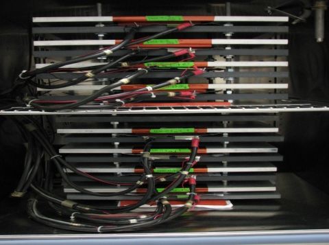
III. Advanced Battery Development
One of the primary objectives of the Energy Storage effort is the development of durable and affordable advanced
batteries and ultracapacitors for use in advanced vehicles, from start/stop to full-power HEVs, PHEVs, and EVs. The
battery technology development activity supports this objective through projects in several areas:
Full-scale battery R&D under multiple battery development contracts—conducted through the United States
Advanced Battery Consortium (USABC),
Numerous advanced cell, materials and components contracts—administered through the National Energy and
Technology Laboratory (NETL), and
Small Business Innovative Research (SBIR)—to fund early-stage R&D for small businesses/entrepreneurs.
All battery development projects are conducted with a set of technical goals in mind and in order to overcome specific
technical barriers which prevent the large-scale commercialization of advanced automotive batteries.
Technical Goals
By 2014, develop a PHEV battery that enables a 40 mile all-electric range and costs $3,400.
By 2022, reduce PEV battery cost to $125/kWh.
Technical Barriers
Cost – The current cost of Li-based batteries is approximately a factor of four too high on a kWh basis for PEVs
and approximately a factor of 50% too high on a kW basis for HEVs. The main cost drivers being addressed are
the high costs of raw materials and materials processing, cell and module packaging, and manufacturing.
Performance – The performance advancements required include the need for much higher energy densities to
meet the volume and weight requirements, especially for the 40 mile PHEV system and longer range EVs, and to
reduce the number of cells in the battery (thus reducing system cost).
Abuse Tolerance – Many Li batteries are not intrinsically tolerant to abusive conditions such as a short circuit
(including an internal short circuit), overcharge, over-discharge, crush, or exposure to fire and/or other high
temperature environments. The use of Li chemistry in the larger (PEV) batteries increases the urgency to address
these issues.
Life – A 15-year life with 5,000 HEV cycles or 1,000 EV cycles is unproven.
Technical Targets
Focus on the small-scale manufacture of cells, batteries, and advanced materials for high-power applications
(HEVs) and high-energy applications (e.g., PEVs).
Attempt to meet the summary requirements for EVs, PHEVs, HEVs, and Lower-energy energy storage
systems (LEESS) developed with industry – as shown in Table III - 1, Table III - 2, and Table III - 3.
Accomplishments
The R&D activity remains fully underway with multiple battery development contracts being conducted through
the USABC.
Numerous advanced cell, materials, and components contracts are ongoing – administered through the National
Energy and Technology Laboratory (NETL).
FY 2013 Annual Progress Report 25 Energy Storage R&D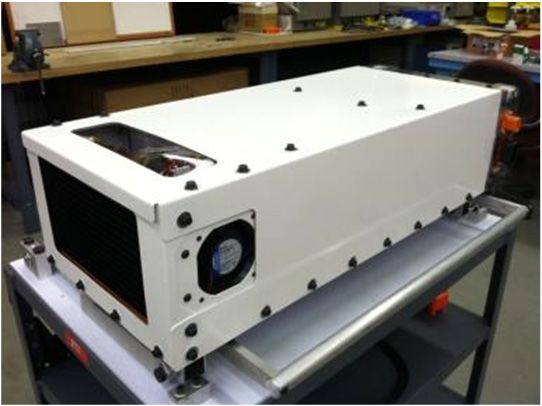
III. Advanced Battery Development                                                                                 Howell – DOE

Table III - 1: Summary of USABC performance targets for EV batteries9
                 USABC Goals for Advanced Batteries for EVs - CY 2020 Commercialization
     End of Life Characteristics at 30°C                Units             System Level              Cell Level
Peak Discharge Power Density, 30 s Pulse                W/L                   1000                    1500
Peak Specific Discharge Power, 30 s Pulse               W/kg                  470                      700
Peak Specific Regen Power, 10 s Pulse                   W/kg                   200                     300
Useable Energy Density @ C/3 Discharge Rate             Wh/L                   500                     750
Useable Specific Energy @ C/3 Discharge Rate            Wh/kg                  235                     350
Useable Energy @ C/3 Discharge Rate                     kWh                     45                     N/A
Calendar Life                                           Years                   15                      15
DST Cycle Life                                         Cycles                   1000                   1000
Selling Price @ 100K units                             $/kWh                     125                   100
Operating Environment                                    °C                  -30 to +52             -30 to +52
Normal Recharge Time                                   Hours              < 7 Hours, J1772       < 7 Hours, J1772
High Rate Charge                                       Minutes        80% ΔSOC in 15 min      80% ΔSOC in 15 min
Maximum Operating Voltage                                 V                     420                    N/A
Minimum Operating Voltage                                 V                     220                    N/A
Peak Current, 30 s                                        A                      400                   400
                                                                       > 70% Useable Energy > 70% Useable Energy
Unassisted Operating at Low Temperature                   %           @ C/3 Discharge rate at @ C/3 Discharge rate at
                                                                               -20 °C                 -20 °C
Survival Temperature Range, 24 Hr                       °C                   -40 to+ 66             -40 to+ 66
Maximum Self-discharge                                %/month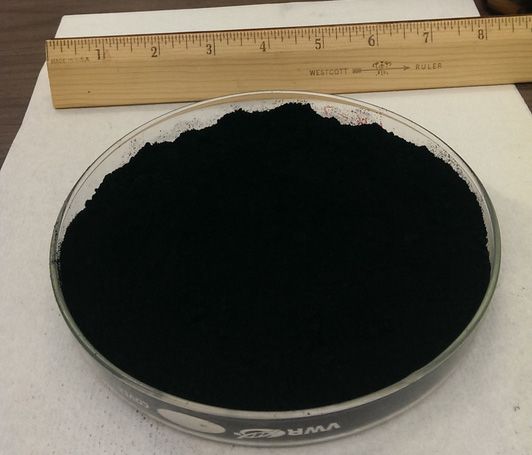
Howell – DOE                                                                           III.A Advanced Battery Development

Table III - 2: Summary of USABC performance targets for PHEV batteries
                                                                         High Power/
                                                                                          Moderate         High Energy/
                                                                           Energy
       Characteristics at End of Life (EOL)                                             Energy/Power       Power Ratio
                                                                            Ratio
                                                                                        Ratio Battery        Battery
                                                                           Battery
 Reference Equivalent Electric Range                          miles          10               20                 40
 Peak Pulse Discharge Power (2 sec/10 sec)                     kW           50/45           45/37              46/38
 Peak Regen Pulse Power (10 sec)                               kW            30               25                 25
 Available Energy for CD (Charge Depleting)
                                                               kWh           3.4              5.8               11.6
 Mode, 10 kW Rate
 Available Energy in CS (Charge Sustaining) Mode               kWh           0.5              0.3               0.3
 Cold cranking power at -30°C, 2 sec – 3 pulses                kW             7               7                  7
 CD Life / Discharge Throughput                           Cycles/MWh      5,000/17         5,000/29           5,000/58
 CS HEV Cycle Life, 50 Wh Profile                             Cycles       300,000         300,000            300,000
 Calendar Life, 35°C                                           year          15               15                 15
 Maximum System Weight                                          kg           60               70                120
 Maximum System Volume                                         Liter         40               46                 80
 Maximum Operating Voltage                                     Vdc           400             400                400
 Minimum Operating Voltage                                     Vdc       >0.55*Vmax      >0.55*Vmax         >0.55*Vmax
 Maximum self-discharge                                      Wh/day          50               50                 50
                                                                             1.4                                1.4
 System Recharge Rate at 30°C                                  kW                      1.4 (120V/15A)
                                                                         (120V/15A)                         (120V/15A)
 Unassisted Operating & Charging Temperature                    °C        -30 to +52      -30 to +52         -30 to +52
 Survival Temperature Range                                     °C        -46 to +66      -46 to +66         -46 to +66
 Maximum current (10 sec pulse)                                Amp           300             300                300
 Maximum System Production Price @ 100k
                                                                 $         $1,700           $2,200             $3,400
 units/year

FY 2013 Annual Progress Report                                 27                                      Energy Storage R&D
III. Advanced Battery Development                                                                                 Howell – DOE

Table III - 3: Summary of USABC performance targets for power assist hybrid electric vehicles
                                             Lower Energy Energy                  Power Assist             Power Assist
           Characteristics
                                            Storage System (LEESS)                (Minimum)                (Maximum)
 Pulse discharge power (kW)                         20 (10 sec)                    25 (10 sec)              40 (10 sec)
                                                     55 (2 sec)
 Peak Regenerating Pulse Power                  30 (10 sec; 83 Wh)             20 (10 sec; 55 Wh         35 (10 sec; 97 Wh
 (kW)                                                                                pulse)                    pulse)
                                                40 (2 sec; 22 Wh)
 Total Available Energy (kWh)                   0.056 (Discharge)                      0.3                      0.5
                                               0.083(Regenerative)
                                                   0.026 (Both)
                                          0.165 (Total vehicle window)
 Cycle Life (cycles)                                   300k                    300k; 25-Wh cycle       300k; 50-Wh cycle (15
                                                                                  (7.5 MWh)                    MWh)
 Cold-cranking Power at −30ºC             5 (after 30 day stand at 30ºC)      5 (three 2-sec pulses,   7(three 2-sec pulses,
 (kW)                                                                         10-sec rests between)    10-sec rests between)
 Calendar Life (years)                                   15                             15                      15
 Maximum System Weight (kg)                              20                             40                      60
 Maximum System Volume (liters)                          16                             32                      45
 Production Price @ 100k                      $400 (Selling price per                 $500                     $800
 units/year ($)                                      system)
 Unassisted Operating temperature                   −30 to +52                     −30 to +52               −30 to +52
 Range (ºC)
 Survival Temperature Range (ºC)                    −46 to +66                     −46 to +66               −46 to +66

Energy Storage R&D                                                28                             FY 2013 Annual Progress Report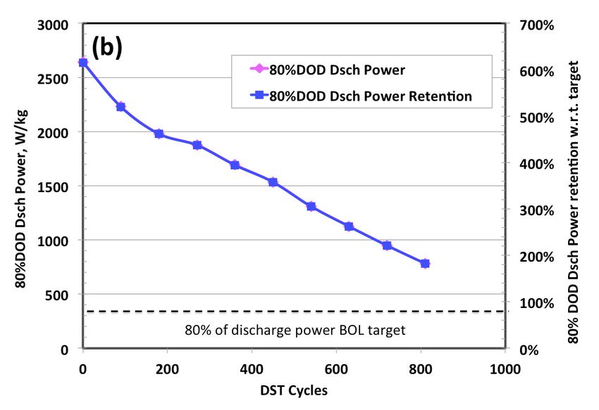
III.A USABC Battery Development Projects
III.A.1 EV Battery Development (Envia Systems)
temperatures and supports long cycle and calendar life.
Harshad Tataria, USABC Program Manager Some specific barriers that have been addressed
Subcontractor: Envia Systems throughout this project are:
High irreversible capacity loss (IRCL)
Herman A. Lopez, Program Manager,
Oxygen loss during cycling (Li2MnO3
7979 Gateway Boulevard
MnO2 + 2 Li+ + 1/2O2), which leads to gassing
Newark, CA 94560
in the pouch cell
Phone: (510) 962-3687; Fax: (510) 372-0318
High DC-Resistance
E-mail: hlopez@enviasystems.com
Fade in average voltage upon cycling
Start Date: December 2010 High Manganese dissolution leading to poor
cycle life and calendar life
Projected End Date: July 2013
Technical Targets
Objectives
Develop a high specific capacity cathode
Develop and evaluate high capacity (>200mAh/g at C/3) able to meet the energy,
manganese rich (HCMRTM) cathode materials power, cycle life, calendar life and cost targets.
and screen various electrolyte formulations Develop and utilize a high voltage, stable
that meet the material target specifications. electrolyte formulation that can operate in the
Design, build and test large capacity pouch temperature range of -40°C to 55°C and be
cells integrating Envia’s HCMRTM cathode and able to support high energy and power, a cycle
optimized electrolyte formulations that meet life of 1,000 cycles and a calendar life of 10
the USABC minimum goals for long term years.
commercialization. Design, develop, build and test >20Ah cells,
which meet the USABC minimum goals for
Technical Barriers long term commercialization of EVs.
One challenge is to develop a cathode material with
very specific electrochemical performance and Accomplishments
incorporate it into a cell expected to meet numerous Envia down-selected an HCMRTM cathode
USABC cell targets. Many of the cell target after extensive material development with
specifications as with the material specifications will respect to composition, dopants and surface
require optimization and balance in order to meet the coatings. The material development consisted
various targets. In the cell, a balance between energy of optimizing the chemical and physical
and power will exist and in the material, a compromise properties of the cathode to improve the
between specific capacity and cycle and calendar life specific discharge capacity, rate capability,
will exist. This project consists of developing the best cycle life, transition metal (TM) dissolution,
materials and integrating them in an optimal cell design and DC-resistance of the material.
to meet the USABC targets.
The down selected cathode materials were
Another challenge is that the HCMRTM cathode is a scaled up to kilogram levels and integrated in
relatively new material. Unlike other more established large capacity cells to support a total of nine
cathode chemistries where there is an abundance of data project cell builds.
and performance trends, HCMRTM cathode data in many A new baseline electrolyte was selected based
occasions (specially for large cell data) is being reported on improved low temperature performance
for the first time. while maintaining similar room temperature
Envia’s HCMRTM/graphite cells potentially operate cycling stability, power and energy
at higher voltages than commercially available cells. In characteristics compared to Envia’s high
order to meet the USABC targets, this will require an voltage baseline electrolyte.
electrolyte that operates at high voltages, low and high
FY 2013 Annual Progress Report 29 Energy Storage R&D
III.A.1 EV Battery Development Tataria – USABC, Lopez – Envia
Envia has met a majority of the stringent Initial testing is performed using coin cells or 1Ah
requirements for electric vehicle (EV) pouch cells and will be scaled up to larger pouch cells.
batteries. Envia demonstrated meeting the Electrochemical and battery testing are being
gravimetric and volumetric power and energy performed, along with material characterization using
targets from 20Ah capacity pouch cells. various analytical techniques.
Results
Introduction In this first USABC project, Envia has met a
majority of the stringent requirements for EV batteries.
Envia Systems proposed to develop large capacity Envia demonstrated meeting the gravimetric and
(20Ah-40Ah) pouch cells based on a novel high-voltage volumetric power and energy targets from 20Ah
lithium rich cathode chemistry containing a layered- capacity pouch cells. Low temperature energy retention
layered structure. The layer-layer composition is made was shown to meet the specifications from room
up of interconnected Li2MnO3 and LiMO2 domains. temperature to -30°C. DST cycle life testing is still
Upon initial charging to high potentials (>4.5V vs Li0), ongoing with the latest data showing greater than 800
the material gets activated resulting in lithium extraction DST cycles (9 RPTs) while both energy and discharge
from the Li2MnO3 component along with the loss of power continue to stay above the 80% beginning of life
oxygen. This lithium removal gives rise to a first cycle (BOL) target (see Figure III - 1).
irreversible capacity loss.
The new cathode chemistry can also be written in
the form of Li1+xNiαCoβMnγO2 where the major TM
component is Manganese, which reduces the amount of
the costlier Nickel and Cobalt components. Having a
high amount of manganese in the structure translates to
high capacity, increased safety, and low cost.
Approach
Our approach is very cathode centric, as we believe
that the cathode is the biggest driver of overall
performance and cost. New lithium-rich cathode
compositions have been created with the layered-layered
structure xLi2MnO3.(1-x)LiMO2 where M= Ni, Co, Mn.
In general, when the cathode chemical composition,
surface nanocoating and morphology are changed, the
cathode specific capacity, IRCL, average voltage, cycle
life, and tap density of the material change. We will also
explore dopants that are able to reversibly intercalate
greater amounts of lithium, while controlling the
oxidation state of the transition metal components (Ni+2,
Co+3 and Mn+4) and retaining the crystal structure of the
cathode.
Another way to engineer and control the cathode
specific capacity, IRCL and average voltage is by
having a nanocoating covering the surface of the
cathode. The nanocoating has been shown to stabilize Figure III - 1: DST cycle life test results in terms of energy (a)
the cathode structure by preventing unwanted side and discharge power (b) for 20Ah capacity pouch cells
reactions with the electrolyte and reducing the amount Calendar life testing is also ongoing with promising
of cathode TM dissolution. As part of the project, results being shown after seven months of testing. The
various nanocoating compositions, as well as coating models to properly predict the calendar life continue to
thicknesses will be explored and optimized. The be developed as more data continues to be collected.
thickness and uniformity of the nanocoating are During the course of the project, the cell-to-pack
dependent on the particle morphology (particle size, conversion factors and pack-related costs were
surface area and porosity) and reaction conditions. calculated by working with a system integration
Energy Storage R&D 30 FY 2013 Annual Progress Report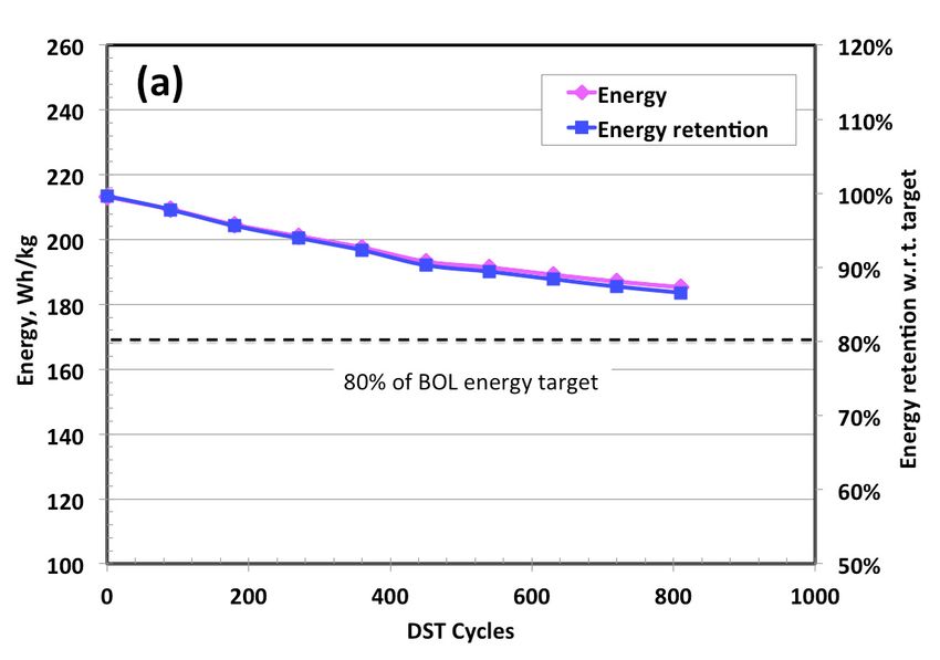
Tataria – USABC, Lopez – Envia                                     III.A.1 EV Battery Development

company. The pack related costs for a 40kWh pack were
determined to be $2,626 and volumetric and gravimetric
energy and power cell-to-pack multiplication factors
found to be 58% and 70%, respectively. Cell cost
analysis was also performed determining the cell related
selling price to be $258/kWh.
     Envia has been successful in meeting most of the
USABC goals for EV batteries. With respect to calendar
life, it is debatable as to whether our cells will meet the
10 year mark. Ideally we would be able to test the cells
for 10 full years to determine this qualification, but that
is not practical. Preliminary calendar life results at 30°C
from our latest cells, suggest promising calendar life
results. Envia continues testing and more data will be
available to validate the calendar life models and life
predictions.

Conclusions and Future Directions
    In its first USABC project, Envia has been able to
meet all of the energy and power goals without
maximizing the energy of the cathode by operating
between 2.2V and 4.35V. As a continuation of the work,
Envia continues to be committed to meeting the
aggressive USABC cell targets to enable widespread
adoption of EVs. Recently, new more aggressive
USABC targets for EVs were made public together with
a request for proposal information (RFPI). In order to
have a better chance to meet the targets, Envia will
propose to integrate high capacity lithium-rich cathodes
with high capacity silicon-based anodes. Only in this
combination can the new aggressive cost and energy
targets be met. During this proposal, Envia will also
partner with leading silicon chemical companies, as well
as with leading electrolyte, separator and pre-lithiation
companies. Having the right partners during the
development will increase the probability of meeting the
technical targets and ensuring that the developed
technology can be mass-produced and commercialized.

FY 2013 Annual Progress Report                                31            Energy Storage R&D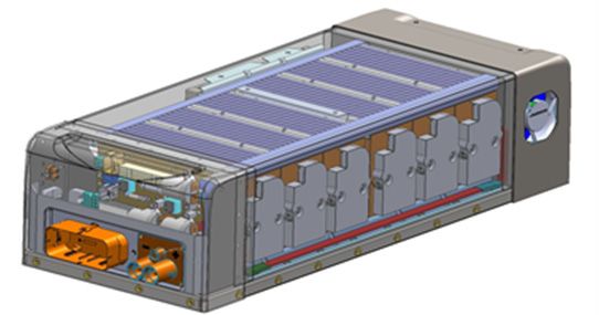
III.A.2 EV Battery Technology Assessment Program (Farasis Energy, Inc.)
Harshad Tataria, USABC Program Manager
Accomplishments
Subcontractor: Farasis Energy, Inc.
Demonstration of over 1,000 cycles in
Keith Kepler, Program Manager prototype small pouch cells cycling at a C/3
21363 Cabot Boulevard rate at 25 C.
Hayward, CA 94545 Manufacture and delivery of 50, 30 Ah Li-ion
Phone: (510) 732-6600; Fax: (510) 887-1211 pouch cells to DOE for evaluation at Idaho
E-mail: kkepler@farasis.com National Laboratory (INL), Sandia National
Laboratory (SNL) and the National Renewable
Start Date: July 2012 Energy Laboratory (NREL).
End Date: August 2013
Objectives
Introduction
Manufacture pouch cells based on BASF
produced HENCM high capacity cathode Farasis Energy, Inc proposed to produce and supply
material and Farasis cell technology. prototype high energy density Li-ion cells to USABC
Conduct performance, life and safety testing of based on their current commercial 25Ah Li-ion pouch
cells in parallel with DOE National cell for detailed testing and evaluation. The cells were
Laboratories. developed using the new transition metal layered-
layered type cathode material originally developed at
Argonne National Laboratory. BASF, a fully licensed
Technical Barriers supplier for this class of material is one of the few
New high capacity and high voltage cathode companies capable of producing these developmental
materials offer great promise in meeting the battery materials on a large scale with commercial quality and
performance and cost goals required for the commercial consistency. Farasis has developed material processing
acceptance of electric vehicles (EVs). However, Li-ion and cell design methods to address some of the inherent
cells using these new materials can experience a range issues associated with the performance and utilization of
of challenges that can limit the full realization of their these cathode materials that have been major barriers to
potential and must be addressed at both the material and their commercialization, despite the major increase in
cell level. These challenges include minimizing gravimetric energy density they offer over current
impedance and achieving acceptable cycle life at commercial cathode material alternatives. Beginning
elevated voltages and temperatures, maximizing cathode with cathode material supplied by BASF, Farasis
material long term stability and ensuring the safety of proposed to process, build and supply Li-ion cells to
large energy dense cells. USABC in a similar form factor to our current 25 Ah
cells but with an almost 20-30% greater energy density.
Technical Targets
Manufacture large, 30Ah Li-ion pouch cells Approach
suitable for EV applications based on BASF
Farasis Energy, Inc currently produces a range of Li-
produced HENCM cathode material.
ion cell and battery products including a 25 Ah, NCM
Demonstrate the potential to meet DOE EV cathode based pouch cell (Figure III - 2). The form
performance and safety goals through factor and performance make it ideal for use in a range
evaluation at Farasis and DOE National of automotive EV systems (Figure III - 3). We proposed
Laboratories. to use this commercial form factor as the basis for the
deliverable prototype cells.
Energy Storage R&D 32 FY 2013 Annual Progress ReportTataria – USABC, Kepler – Farasis III.A.2 EV Battery Technology Assessment
Figure III - 2: Commercial 25 Ah Li-ion pouch cell
Figure III - 3: Rate capability of 25 Ah Li-ion pouch cell
To ensure the greatest performance and to enable us
to optimize the cell design and material utilization, Results
Farasis started with BASF’s HENCM “Layered-
layered” cathode material produced from their pilot Farasis manufactured both small pouch cells and
manufacturing plant to make the cells. Additional large pouch cells as deliverables for this program.
processing of the materials prior to building the cells Cathode material from BASF was processed at
was conducted at Farasis. Initial batches of small Farasis Hayward and then used at its manufacturing
prototype pouch cells were planned to deliver to DOE facility to make pouch cells on its pre-production line.
for initial evaluation. Figure III - 4 shows cycling data from prototype small
pouch cells cycled at C/3 discharge rate.
FN 1.9Ah FEI-2 Pouch Cells
C/5 Charge, C/3 Discharge
2.50
2.00
Discharge Capacity (Ah)
1.50
1.00
0.50
0.00
0 100 200 300 400 500 600 700
Cycle Number
Figure III - 4: 2.0 Ah Li-ion pouch cell cycling data: C/5 charge, C/3 discharge
FY 2013 Annual Progress Report 33 Energy Storage R&DIII.A.2 EV Battery Technology Assessment Tataria – USABC, Kepler – Farasis
Figure III - 5 shows cycling data for several early before the final production build. These cells were
prototypes of the 30 Ah cell design tested at Farasis cycled with a C/3 charge and discharge rate.
FEI-2 30Ah Large Pouch Cells
C/3 Charge, C/3 Discharge
35000
30000
Discharge Capacity (Ah)
25000
20000
15000
10000
5000
0
0 50 100 150 200 250 300
Cycle
Figure III - 5: 30 Ah Li-ion pouch cell cycling data: C/3 charge, C/3 discharge
Farasis shipped a large quantity of processed and DOE aimed at meeting the USABC PHEV battery
cathode material to its factory in March 2013 for the performance targets. These cells will be evaluated both
final deliverable cell build. Approximately 80 30 Ah at Farasis and at the National Laboratories over the
cells were built at the factory using a design based on coming months. Farasis will continue its development of
the 25 Ah production pouch cell form factor. Seventy this high capacity Li-ion cathode chemistry to further
cells were shipped to Farasis in Hayward, CA and 46 of improve the performance of this system. This
these cells were shipped to Idaho National Laboratory technology has the potential to meet the long term
for performance testing, Sandia National Laboratory for USABC goals for PHEV and EV battery systems.
safety testing, and the National Renewable Energy
Laboratory for thermal evaluation. The cells will be
tested at these facilities and at Farasis over the next 6
months.
Conclusions and Future Directions
Farasis has successfully delivered large high energy
density Li-ion pouch cells for evaluation by USABC
Energy Storage R&D 34 FY 2013 Annual Progress ReportIII.A.3 EV Battery Technology Assessment (SK Innovation)
Table III - 4: Summary of USABC targets for the system being
Chulheung Bae, USABC Program Manager developed
Subcontractor: SK Innovation
Parameter(Units) of USABC
fully burdened system minimum goals
Kyungjin Park, Program Manager
325 Expo Road, Wonchondong, Yuseongku, Power density (W/L) 460
Specific power
Daejeon, Korea 300
Dis. 80% DOD/30s (W/kg)
Phone: (82) 42-609-8133; Fax: (82) 42-609-8740 Specific power
150
E-mail: kj.park@sk.com Regen, 20% DOD/10s (W/kg)
Energy density
230
Start Date: November 2012 C/3 Discharge rate (Wh/L)
Specific energy
Projected End Date: January 2014 C/3 Discharge rate (Wh/kg)
150
Specific power/Specific energy ratio 2:1
Objectives Total pack size (kWh) 40
Life (Years) 10
Develop and validate a pure NCM battery
Cycle life - 80% DOD (Cycles) 1,000
system Power & Capacity degradation
o High energy density 20
(% of rated spec)
o Long life performance -40 to +50
o High abuse tolerance Operating environment (℃) 20% performance loss
(10% desired)
6 hours
Technical Barriers Normal recharge time
(4 hours desired)
20-70% SOC <
One of the concerns about pure NCM system is 30minutes
safety. Therefore, improved ceramic coated separator High rate charge @150 W/kg
(III.A.3 EV Battery Technology Assessment Bae – USABC, Park – SK Innovation
E400 could maintain other electrical performance as in Approximately, 4 cycles are accumulated per day
previous systems. and RPTs are being conducted every 100 cycles
(~1/month). Figure III - 7 shows C/3 capacity retention
and results show 91.3% of retention at 800 cycles.
Approach Similar tendency is seen in DST capacity retention
(92.7%) and peak power retention (94.7%).
SKI applied pure NCM as cathode material to get
high energy density and to avoid crucial deterioration at
high temperature. However, high Ni-content NCM has a
detrimental effect on the abuse tolerance and cycle life.
In order to obtain structural stability, SKI has researched
surface-coated NMC with stable materials. The surface-
treated particles have shell-core morphology, that is,
SC-NMC.
In addition, we enhanced the separator properties to
minimize shrinkage of the separator at high
temperatures, and developed the new electrolyte system
which is an optimized formulation for the new cathode.
Cycle life and calendar life are expected to improve
significantly after eliminating the Mn-spinel. Figure III - 7: C/3 capacity retention of LMO-free E400 in cycle
life
Calendar life tests are ongoing at four different
Results temperatures of 25, 35, 45, and 55°C. Each battery is
charged to SOC 100% at the C/3 rate and allowed to rest
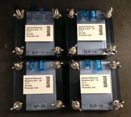
Core Test. SKI tested 18 cells in total (6 cells for
in an open circuit condition at the desired temperature
cycle life and 12 cells for calendar life) and measured
for 4 weeks. At the end of 4 weeks, the batteries
that the average capacity is over 40 Ah at current
undergo RPTs at 30°C. Figure III - 8 shows C/3
condition of C/3, C/2 and C/1 (Figure III - 6).
capacity retention at four temperatures after 24 weeks
and the results show 94.4%, 91.5% 87.4% and 81.0%,
respectively.
Figure III - 6: Constant current discharge test for LMO-free
E400
100% DST Discharge capacity at the DST power of
400W/kg is 40.8Ah on average.
Figure III - 8: C/3 capacity retention of LMO-free E400 in
Peak power capability was calculated as shown calendar life
below and showed a result of over 670W/kg.
There is no significant degradation to 45°C and
Peak power=Imax∙(VIRFree+R∙Imax) similar tendency is shown in DST capacity retention
(96.1%, 92.4%, 89.0% and 82.2% at 25 , 35 , 45
48h stand test showed very stable capacity
and 55 , respectively; after 24weeks).
retention with 0.95% capacity loss.
However, comparatively high degradation is
Life Performance. After successfully completing observed at 55°C and this appears clearly in peak power
the core tests, six batteries have been in testing for cycle retention (98.4%, 95.8%, 92.9% and 76.8% at 25 ,
life. Cycle life tests will be conducted until End of Life
35 , 45 and 55 , respectively; after 24 weeks). We
(EOL).
can presume that unstable SEI forms on anode surface
Energy Storage R&D 36 FY 2013 Annual Progress ReportBae – USABC, Park – SK Innovation III.A.3 EV Battery Technology Assessment
from electrolyte decomposition between 45°C and 55°C, 1mΩ and 10mΩ) were given by SNL for this program.
and it brings comparatively high capacity irreversibility. Abuse tests were performed and the tested cells met
Abuse tests were carried out and LMO-free E400 most of the established goals, with the exception of the
showed stable behavior after abuse tests as shown in thermal ramp test. In the case of thermal ramp test, the
Table III - 5. SKI followed SAND 2005-3123 abuse objective of the test is monitoring thermal onset through
tests manual which was distributed by SNL, and some temperature increase. The LMO-free cell turned out to
specific test conditions (e.g., resistance for short circuit; be stable up to 180°C.
Table III - 5: Summary of abuse test results for LMO-free E400
Conclusions and Future Directions
SKI has evaluated LMO-free E400 and cycle life
and calendar life will be continuously conducted until
RPT10. Currently, based on capacity retention of 80%,
cycle life is expected to exceed 2,000 cycles and
calendar life of over 70weeks at 45 and 100% SOC –
SKI will estimate battery life with RPT10 data at the
end of the program. SKI would like to continuously
develop and modify cell design including electrolyte
optimization and adjustment of cathode formulation in
order to improve safety further.
FY 2013 Annual Progress Report 37 Energy Storage R&DIII.A.4 Advanced High-Performance Batteries for Plug-In Hybrid Electric
Vehicle Applications (JCI)
Packaged Energy Cost: $250/kWh for cell.
Renata Arsenault, USABC Project Manager
EUCAR 4 abuse tolerance rating or better.
Subcontractor: Johnson Controls Inc.
Avie Judes, JCI Program Manager Accomplishments
5757 N. Green Bay Road Evaluated multiple cathode materials from six
Glendale, WI 53209 suppliers. Two materials remain as candidates
Phone: (414) 524-6173 after exhaustive down selection trials.
E-mail: avie.judes@jci.com Mid-program cells demonstrated a 25%
capacity increase.
Start Date: April 1, 2012 Projected final cell design translates to 40%
End Date: March 31, 2014 cost reduction at the system level.
Dry compounding trials achieved desired
reduction of solvent and binder. High
Objectives resistance growth and cost have eliminated this
process technique going forward.
Build on the prismatic cell platform developed
in the previous program and achieve a step- Paste mix processing was evaluated using an
change in energy density from 275 Wh/L to a in-line compound mixer as a potential enabler
375 Wh/L. stretch goal. of solvent reduction goals. Promising results
were obtained, attaining the high electrode
Achieve cost target of $250/kWh for the densities needed for the cell energy density
prismatic cell. targets. Testing through December 2013 will
Target EUCAR 4 abuse tolerance rating or assess potential for anode and cathode high
better. solids processing.
Deliver two generations of prismatic cells. Evaluated 4.2V and 4.3V upper voltage limits
in parallel with electrolyte development (base
Technical Barriers solvents and additives) for enhanced stability.
Demonstrated results at 4.2V have allowed
Higher specific capacity cathode materials of Vmax increase from 4.1V.
interest have reduced thermal stability
Mechanical improvement activity resulted in
(reduced life).
mandrel elimination as well as current
Novel electrode material processing techniques collector and coating area optimization, plus
may have a negative impact on performance alternate fill hole closure method down-
and life. selection. Results inform final build choices.
Lowering the power to energy ratio must not Abuse tolerance improvements focused on
result in an unacceptable reduction in low Thermal Protective Barrier (TPB), ceramic
temperature power. coating on anode, ceramic separators,
Higher upper voltages adversely affect life and electrolytes and cathodes with functional
require countermeasures to stabilize the overcharge additives, all leading to improved
chemistry. over-charge protection and enhanced
Abuse tolerance improvements require understanding.
material and process innovation to overcome
impact on life and cost.
Technical Targets
Introduction
Available Energy (Charge Depleting mode):
5.8 kWh for 20-mile system at End of Life In 2011, JCI completed a three-year program which
(EOL). developed a first generation NMC-graphite, rigid
Energy Density: 375 Wh/L (stretch goal). prismatic cell technology headed for commercialization
Energy Storage R&D 38 FY 2013 Annual Progress ReportArsenault – USABC, Judes – JCI III.A.4 Advanced High-Performance Batteries for PEV Applications
in late 2013. This $4.1 million, 2 year follow-on upward march in energy density continued, through
program builds on the first generation platform. The continuous improvements made in process, materials
theme of this program is to achieve a major energy and mechanical design. This improvement is seen in
density improvement of the cell. Figure III - 9.
Between the conclusion of the previous
program and the kick-off of this program, the
Figure III - 9: Energy density roadmap
Higher Energy Density Materials. JCI is focusing
Approach on high-nickel NMC cathode materials. Compared to
the baseline NMC111, high-nickel materials exhibit
The objective of the program is to increase the reduced structural and thermal stability, manifested by
energy density of the cell technology and drive down accelerated aging and lower abuse tolerance. To address
the cost to capacity ratio, either directly (with increased this, stabilized active materials (doped, coated, and / or
mAh/g, reduced BSF and cost) or indirectly (with surface treated) from six global suppliers were
improved critical enablers: life and abuse tolerance). evaluated.
The focus is on active materials that fall midway on the Lithium-rich layered-layered cathode materials are
‘state-of-the-art’ to ‘high-risk’ continuum, striving to also being evaluated to identify the main barriers that
exploit their full, unrealized potential through concerted need to be overcome prior to commercialization.
material, process, and mechanical design innovation. Electrode Processing Optimization. Novel slurry
Specifically, the family of LiNixCoyMnzO2 (where processing techniques are being studied with two
x>1/3) is targeted for the positive electrode coupled with objectives: 1) reducing the quantity of N-Methyl
a graphitic negative material. Module and system Pyrrolidinone (NMP) solvent used in the positive
development have been excluded from the program to electrode manufacturing process by 18-22% (result: cost
focus resources on closing the gap in cell technology. If reduction) and 2) improving the electrode handling
achieved, derivative system-level benefits of cost, through calendaring and winding to support electrode
volume and mass reduction will be realized and gap densification (result: increase in cell energy density).
chart targets will be met.
Drivers for the amount of solvent, conductive agent
Increased energy density is being pursued on four and binder used in the current process are intimately
discrete levels: 1) active material specific capacity linked to the type of mixing applied. JCI’s process uses
increase, 2) electrode composition (increased active the classic industry approach for solids dispersion.
material to inactive constituents ratio, 3) electrode Alternative methods of first compounding or pre-mixing
densification, and 4) maximizing space occupied by the active material with the conductive agent are being
electrode coil in the cell envelope and increasing coated explored as paths to solvent reduction and associated
electrode width. increase in active to inactive material ratios and energy
The following five improvement areas form the density.
framework of the program, and all converge toward the
central program goal of reducing the $/kWh metric. Electrode Design Optimization. Electrode
optimization focuses on reducing the power to energy
FY 2013 Annual Progress Report 39 Energy Storage R&DIII.A.4 Advanced High-Performance Batteries for PEV Applications Arsenault – USABC, Judes – JCI
ratio (P:E) to the practical boundary where acceptable are: thin wall cans with special features, mandrel
performance and life characteristics are maintained. elimination, current collector design optimization,
This is being achieved by the aforementioned reduced foil margin (wider electrode coated width),
campaigns to increase specific capacity of the active electrolyte fill hole closure using torsional ultrasonic
material, increase energy density of the coated welding, and low pressure vent development.
electrodes, and increase the loading level itself. WBS 5.0 Abuse Tolerance. Abuse tolerance
Increased Upper V Limit and Increased SOC improvement is a critical enabler to all other work
Window. Increasing the upper voltage limit beyond its aimed at increasing energy content of the cell, and is
current value of 4.1 V offers increased energy density being pursued on multiple parallel fronts:
and reduced $/kWh, but may adversely impact life and High temperature separator. JCI is working
abuse tolerance. To surmount these issues, stabilized closely with separator developer Entek to
active materials and electrode and interface stabilization optimize their ceramic filled separator
will be evaluated. technology and solve several manufacturing
Stabilization of the negative electrode/electrolyte related issues.
interface would in turn allow expansion of the SOC JCI’s Thermal Protective Barrier (TPB)
window beyond 70% thus offering an opportunity to technology. JCI applied TPB on the anode in
reduce the Battery Size Factor (BSF) and hence cost. the last program and are now optimizing TPB
Test efforts seek the lowest operating voltage limit coating, including thickness, coverage, and
where the inevitable trade-offs in life remain acceptable uniformity.
in magnitude. Expansion efforts would focus on moving Overcharge protection additives. These are
from 25 to 95% SOC to a stretch goal of 15 to 95% being tested both in the electrolyte and in the
SOC. electrode itself.
Mechanical Design and Advanced
Manufacturing. Significant effort is directed at
advancing the cell design and manufacturing processes, Results
striving to minimize the void volume in the cell and
achieve a step-change reduction in component and For discussion purposes, the key design versions
assembly costs. Some of the concepts being investigated from the previous program are defined in Table III - 6.
Table III - 6: Version parameters and base & mid-program performance
1C_Rate Energy Discharge Power Discharge R
P/E
Cell Type Size Capacity Density (10s, 50%SOC) (10s, 50%SOC)
Ratio
(Ah) (Wh/L) (W) (mOhm)
USABC 4th Build
141x124x22.6 23.7 245 1510 1.99 17
(Last Program)
Baseline
148x91x26.5 27.0 275 1540 1.92 16
New Program
Mid-Program 148x91x26.5 33.3 345 1880 1.60 16
Final 148x91x26.5 36 375 TBD TBD TBD
The new electrolyte additive developed in the last The prismatic cell representing mid-program results
program and anode active material implemented in the has an increased energy density of 26%. It shows good
baseline cell have remarkably low cell resistance growth discharge and regeneration power capability, with
during storage at elevated temperatures. This can be similar power/energy ratio as baseline. With increased
seen in Figure III - 10, which shows cell resistance upper voltage at 4.2V, the resistance growth in calendar
increasing only 13% and 34% after one year calendar life at 60˚C is higher than baseline at 4.1V after 100
life at 45°C and 60°C respectively. days. However, their capacity fade remains the same as
the baseline at 4.1V, as seen in Figure III - 11.
Energy Storage R&D 40 FY 2013 Annual Progress ReportArsenault – USABC, Judes – JCI III.A.4 Advanced High-Performance Batteries for PEV Applications
PL27M Baseline Calendar Life at 100%SOC
120% 110%
100% 90%
80% 70%
Capacity Retention (%)
Resistance Increase (%)
30C
60% 45C 50%
60C
40% 30%
20% 10%
0% ‐10%
0 50 100 150 200 250 300 350 400
Days
Figure III - 10: Baseline prismatic cell calendar life
60°C Calendar Life at 100% SOC
120% 100%
Baseline at 4.1V
Mid‐Program at 4.2V
100% 80%
Cell Resistance Increase (%)
Capacity Retention (%)
80% 60%
60% 40%
40% 20%
20% 0%
0% ‐20%
0 50 100 150 200 250 300 350 400
Days
Figure III - 11: Mid-program cell calendar life at 60C
Results by development area at month 18 (of 24) are Development activities have improved its capacity fade
presented below: over initial versions, but end of life (EOL) capacity is
Higher Energy Density Materials. Six suppliers of lower than baseline (111) at EOL.
candidate nickel-rich NMC have been engaged and the Three NMC materials have been down-selected as
materials (designated Cat_1 through Cat_6) are at candidates for the final design, the baseline material
various stages of testing. Different NMC stoichiometries (Cat_1), Cat_2 NMC (442) and Cat_4 (improved 111).
have been evaluated to identify high energy materials Lithium-rich layered-layered oxide cathode material
with good power and life. The tests have shown that the was evaluated paired with a high voltage electrolyte in
high nickel NMC has low thermal stability. Despite high 1-3 Ah pouch cells. It has very poor capacity fade, and a
initial capacity, high nickel NMC suffers high capacity large voltage fade during cycle life. Further work with it
degradation and poor life at high temperatures. Several is not planned.
suppliers provided high nickel NMC with surface
treatment, but this significantly increased cell resistance.
FY 2013 Annual Progress Report 41 Energy Storage R&DIII.A.4 Advanced High-Performance Batteries for PEV Applications Arsenault – USABC, Judes – JCI
Electrode Processing Optimization. The two shown high resistance and poor calendar life behavior.
approaches studied for solvent reduction through This is attributed to the excessive shear undergone by
improved electrode processing methods are shown in the material during compounding. This process is no
Figure III - 12. Dry compound mixing yielded material longer being considered for high solids mixing.
which met solvent reduction targets, but cell testing has
Figure III - 12: High solids mixing approaches using dry compounding (left) and paste mix (right) methods
A second method being tested to achieve the high for the cathode has shown minimal adverse impact in
solids targets is paste mixing. With this method, cell testing. Primary efforts have focused on quantifying
materials are combined with a portion of the solvent in the potential corrosion effects of the water-based
an in-line compound mixer to achieve the work needed cathode slurries as this corrosion can have detrimental
for the initial combination of materials to contribute to effects on life and cell resistance. Evaluations indicate
reduced solvent demand. The internal workings of this no impact on stability of the water-based slurry with 30
pre-blending equipment are shown in Figure III - 13. minutes of contact with aluminum foil, well beyond the
Following initial trials, equipment was rented and normal processing time before electrode drying. Scaled
installed in the JCI Pilot line for further testing of up mixing and electrode processing is scheduled for
electrode processing and resulting cell evaluation. Initial February 2014.
electrodes produced, shown in Figure III - 13, appear Electrode Design Optimization. Different
promising for achieving good uniformity with approaches were tested to optimize electrode design.
calendaring to the high density targets for improved Higher electrode loading was proven not to be efficient.
energy density. Electrode quality after calendaring is a Electrode densification delivered more capacity, and
significant accomplishment not realized with previous better power and life. A new conductive carbon has
trials. A solvent reduction of 13% was achieved, still improved electrode processing and cell performance.
below the 18% target. However, optimization work The anode optimization has been applied in the mid-
continues. program cells.
Increased Voltage Limit. Accelerated testing began
with prismatic cells at upper voltages of 4.1, 4.2 and
4.3V. The 4.2 V group showed acceptable power and
energy fade. The first generation (baseline) 4.3 V tests
were stopped due to poor results. Chemistry
stabilization improvements have demonstrated life at
4.2V that meets EOL targets. 4.2V has been selected as
the standard upper voltage limit.
A few electrolyte additives tested at 4.3V imparted
Figure III - 13: Paste mixing equipment and electrodes some stability improvement. Overall, however, capacity
saw a crossover with cells at 4.2V.
An alternate (higher risk/higher reward) process
incorporating aqueous binder (allowing total solvent To maximize cell energy utilization, the usable SOC
elimination) was pursued for the positive. This offers a window was widened from 95%-25% to 95%-15%
significant cost reduction opportunity by avoiding the SOC. The cycle life of baseline cells has shown
need to capture the evaporated NMP solvent from the excellent performance, even with the expanded SOC
electrode process. The application of water-based binder window (see Figure III - 14).
Energy Storage R&D 42 FY 2013 Annual Progress ReportArsenault – USABC, Judes – JCI III.A.4 Advanced High-Performance Batteries for PEV Applications
Figure III - 14: PHEV cycle life: 95%-25% vs 95%-15%SOC
Mechanical Design and Advanced successfully developed in a production-like
Manufacturing. Numerous concepts were studied that environment (Figure III - 15). The approach
have the potential to dramatically drive down shows great potential to reduce cell void
component cost and assembly complexity, increasing volume and replace baseline rivet insertion.
cell energy density and performance. The design of a thin wall can with inwardly
embossed features was completed. It has the
Torsional ultrasonic welding was selected as
potential to reduce the complexity of tolerance
the lead alternative fill hole closure method
management and clamping forces needed in
after extensive evaluation of competing
future module designs.
methods. The novel sealing process was
Figure III - 15: Cell sealed by torsional ultrasonic welding
Mandrel-less cells produced in the mid-term might avoid or mitigate thermal runaway.
build are on test with promising results and are Abuse testing with prototypes is planned.
planned for incorporation into the final build. Abuse Tolerance: Joint trials were conducted with
Current collector width was optimized using Entek to address manufacturing and performance issues
results of component level high current pulse of the ceramic filled separator. These separators
tests. This, along with foil margin reduction provided remarkable improvement in cell resistance,
and electrode layout redesign, increased cell power capability, and life. At 25°C, cell power
capacity by 4.5%. improved by 30%, and 20% at -25°C. In calendar life at
A low pressure vent is being developed to 60°C, no resistance increase was measured after 262
investigate whether earlier activation and days at 4.1V.
associated release of thermal energy and fuel
FY 2013 Annual Progress Report 43 Energy Storage R&DIII.A.4 Advanced High-Performance Batteries for PEV Applications Arsenault – USABC, Judes – JCI
PL27M 60°C Calendar Life at 4.1V
120% 110%
100% 90%
Cell Resistance Increase (%)
Capacity Retention (%)
80% 70%
Baseline
R12332010 ‐ Type 1.65 Filled
R12332014 ‐ Type 1.65 Filled
R12333013 ‐ Type 2.5 Filled
60% 50%
R12333014 ‐ Type 2.5 Filled
40% 30%
20% 10%
0% ‐10%
0 50 100 150 200 250 300 350 400
Days
Figure III - 16: Ceramic separators calendar life at 60°C
Excellent performance was also found when cells impact on life detected thus far. A formulation of
with ceramic filled separators were tested at 4.2V at electrolyte additives for overcharge control showed very
70°C. After one year storage, cell resistance only promising results with more work required.
increased 34%.
Ceramic filled separators lack the shutdown function Next Steps
which is considered to be an essential safety attribute for
high energy cells. Efforts with Entek to adjust the Convergence of design choices based on this work
ceramic/ polyolefin ratio to achieve full or partial has started. From this, final cells will be produced and
shutdown and retain the life-enhancing properties were delivered in CY Q1 2014.
not successful.
Thermal Protective Barrier (TPB) technology was
optimized on thickness, coverage and uniformity, FY 2013 Publications/Presentations
resulting in tangible improvements in abuse tolerance
1. Presentation to the 2013 DOE Annual Peer Merit
results.
Review Meeting (May 13, 2013).
Two cathode additives were found to delay the onset
of thermal runaway during overcharge with no adverse
Energy Storage R&D 44 FY 2013 Annual Progress ReportIII.A.5 Development of a High-Performance PHEV Battery Pack (LG Chem)
Paul Groshek, USABC Project Manager Technical Targets
Contractor: LG Chem Power, Inc.
Establish the high specific energy of new
Mohamed Alamgir, Program Manager generation of Mn-rich cathode materials.
E-mail: alamgir@lgcpi.com Demonstrate both cycle- and calendar-life
1857 Technology Drive under USABC test conditions.
Troy, MI 48083 Develop a cooling system that is electrically
Phone: (248) 291-2375; Fax: (248) 597-0900 and mechanically robust and efficient.
Develop a pack design that is modular, easy to
Subcontractor: manufacture and close to the USABC cost
LG Chem, Seoul, South Korea target.
Start Date: January 1, 2008 Accomplishments
Projected End Date: March 31, 2010 Extensive studies of the material and electrode
properties such as morphology, surface area
and porosities were carried out to identify
Objectives
electrode formulations optimal from
This is a 24 month program focused on performance as well as from life points of
developing a Li-ion pack technology that view.
meets the energy, power and life requirements Process variables such as formation conditions
of the 40-Mile PHEV program of the USABC. which affect the amounts of gas generated as
A key part of the work is aimed at developing well as life have been examined and
a cell that will significantly reduce cost to meet optimized.
the USABC pack cost target by utilizing high Since this high capacity cathode material
specific energy cathode materials. necessitates the use of high-voltage electrolyte
An important objective of the program is also additives to prolong life at high voltage have
to develop an automotive-grade, self-contained been studied.
battery pack using a refrigerant-based cooling Cyclability of the cathode has been found to be
system. The goal is to increase the efficiency strongly dependent on the charge voltage as
of the thermal management system to increase well as the SOC window of operation. Key
life, lower cell count and more importantly, among the root causes for cell degradation is
lower pack cost. The system is expected to be the dissolution of Mn from the cathode
much more efficient and robust than its liquid- particles and subsequent passivation of the
cooled counterpart commonly used in PHEV anode.
packs. Stabilization of the cathode particle surface
leads to significantly improved life
Technical Barriers characteristics.
The project is addressing the following technical Material we have developed in-house
barriers. demonstrates state-of-the-art cathode capacity
as well as life. Current estimates show that this
(1) Validation of the high capacity of new
material when fully developed will lead to a
generation of Mn-rich cathode materials.
cell cost target of below $200/kWh.
(2) Demonstration of cycle-life of > 5,000 cycles The thermal system and pack volumetric
(3) Demonstration of calendar-life of 15 years efficiency have been significantly improved by
(4) Make considerable progress towards achieving optimizing compressor and evaporator designs,
the USABC pack cost target of $3,400. as well as by improving the contact between
the thermal fins and the cold plate.
Modules and packs have been designed, built
and delivered to the National Labs for testing.
FY 2013 Annual Progress Report 45 Energy Storage R&DIII.A.5 Development of a High-Performance PHEV Battery Pack Groshek – USABC, Alamgir – LG Chem
performance as a function of charge voltages, modified
cathode particle surfaces using a variety of approaches,
studied a range of electrolytes and optimized cell
Introduction process parameters such as formation conditions, etc.
These studies led to the following key observations.
Development of a cost-effective, high performance
battery is a prerequisite for the successful introduction Durability of the cell is critically dependent on the
of PHEVs and EVs. The advent of new high specific charge voltage. Operation above ~4.35V leads to
energy cathode materials has opened up significant significant reduction in cycle-life. Cathode
opportunities to achieve this objective. Low-cost, high surface modification and electrolyte composition
capacity cathode materials using a large operational appear to mitigate these drawbacks to some extent
SOC window will result in the use of less of active (Figure III - 17, Figure III - 18).
materials, thus lowering the pack cost. In addition, a. Considerable amount of gas generation takes
development of a thermal management system that is place during activation and high voltage
more robust and simpler to implement than operation. This causes significant cell swelling
conventional, liquid cooled system is also important for and premature cell failure. Surface treatments
advanced, next generation battery pack technologies. of the cathode particle show good
improvement.
Approach b. Voltage sagging appears to stem from the
continuous structural evolution of the cathode
To achieve the proposed objectives for a 40-Mile material. Surface coatings do not appear to be
PHEV program, we have been studying cell chemistries effective in alleviating this phenomenon.
based on next-generation Mn-rich layered-layered c. Dissolution of Mn from the cathode and its
compounds, our patented Safety Reinforcing Separator migration to and subsequent passivation of the
(SRS) and a laminated packaging cell design. The goal anode remains the key mechanism that appears
is to understand, develop and optimize this cathode to control the life of this Mn-rich high capacity
chemistry, corresponding anode and electrolyte cathode. Modification of the particle surface
compositions in order to meet the USABC targets for using coatings appears to significantly improve
performance, life and cost. Evaluation of critical factors the life of the cell.
such as cathode and anode compositions, effect of Pack Development. As mentioned above, we have
binders and electrolyte compositions as well as the developed a compact and self-contained battery pack
identification of conditions optimum for cycle- and system utilizing a refrigerant-to-coldplate cooling
calendar-life are the important tasks of the program. concept, (Figure III - 19). The essential components for
Another important aspect of the work is to develop a this cooling system are solid fins, a cold plate,
pack that has superior thermal management using compressor and evaporator. Studies were carried out to
indirect cooling entailing a refrigerant-cold plate optimize these components with respect to cooling and
system. This work is aimed at developing a thermal volumetric efficiency, manufacturability and cost. For
system that will be thermally and mechanically robust example, we studied compressors of different ratings
with optimized volumetric and gravimetric efficiencies (e.g., 12V, dual 12V or a single 24V) to determine their
as well as cost. efficacy in thermally managing the cells during cycling.
Two iterations of module and pack builds have been
carried out in course of the program.
Results
Characterization of the Mn-rich cathode. The
layered-layered compound xLi2MnO3(1-x)LiMO2 with
reported capacities > 250 mAh/g. has one of the highest
specific energies of any high voltage cathode material
currently being studied. To obtain such high capacity,
however, the material needs to be charged to voltages
around 4.6V. Additionally, it is characterized by high
surface area and low conductivity at low SOCs. There is
also the phenomenon of voltage sagging throughout life
that lowers cell energy and is also undesirable from
battery control point of view. To improve upon these
drawbacks, we carried out systematic studies to
optimize electrode formulations, evaluated cell
Energy Storage R&D 46 FY 2013 Annual Progress ReportGroshek – USABC, Alamgir - LG Chem III.A.5 Development of a High-Performance PHEV Battery Pack
250
120 Co
Ref_4.4 V Ni
115 2ALD_4.4 V Mn
200
110
TM Concentration (ppm)
Normalized Capacity (%)
105
100 150
95
90 100
85
80 50
75
70 0
0 1 2
0 50 100 150 200 250 300 350 400 450 500 550 Anode Sample Number
Cycle Number
600
Ref ALD
120
Ref_4.5 V 500
TM concentration (ppm)
115 2ALD_4.5 V Co
Ni
110
Normalized Capacity (%)
400 Mn
105
100 300
95
90 200
85
100
80
75
0
70 Form. 300cycle Form. 300cycle
0
0 50 100 150 200 250 300 350 400 450 500 550 ICP Analysis on Anode
Cycle Number
Figure III - 18: Top) Effect of formation voltage on the amount
Figure III - 17: Effect of charge voltage and surface coatings of transition metal deposited on carbon anode. Sample 1 was
on cycle-life. Top: Data showing the beneficial effect of ALD formed at 4.6V. Sample 2 was formed at 4.4V. Note the
surface coating on the cycle-life at 45°C. The cell was significantly large quantity of Mn deposited at 4.6V. Bottom)
charged at 0.5C and discharged at 1C. Bottom: When the Effect of surface coating on Mn dissolution. ALD coating
charge voltage was raised to 4.5V, instead of 4.4V as in Top reduces Mn dissolution both during formation as well as
figure, there is a substantial decline in cycle-life cycling
The packs were subjected to automotive drive-cycles
to assess their capability in thermally managing the cells
during cycling. Figure III - 20 shows the data for a pack
using a dual 12V compressor system and cycled at an
ambient temperature of 40°C and US06 drive pattern.
The data show that the cooling system was effective in
maintaining the cell temperatures at around 32°C. It
took ~30 mins to reach the steady-state. The bottom
picture compares the efficiencies of packs using
different compressors. The dual 12V system showed the
best efficiency in cooling the packs. The steady-state,
however, for all three packs were reached within ~30
mins. The cold-plate temperatures for the three systems
are also plotted. A key observation from all our pack
data is that the thermal system was efficient in cooling
the cells and maintaining the modules within a narrow
range of temperature.
FY 2013 Annual Progress Report 47 Energy Storage R&DYou can also read