Guidance Document: Positive Input Ventilation (PIV) Systems - Issue 3 - June 2021
←
→
Page content transcription
If your browser does not render page correctly, please read the page content below
Guidance Document:

Positive Input Ventilation (PIV)
Systems
Issue 3 – June 2021
CONTENTS
    1.     INTRODUCTION
    2.     DEFINITIONS
    3.     CONCEPT AND BACKGROUND OF PIV
    4.     INSPECTION CONSIDERATIONS
    5.     OCCUPIER ENGAGEMENT
    6.     INSTALLATION
    7.     ENHANCEMENT EXTRACT FANS
    8.     COMMISSIONING
    9.     OPERATIONAL MODES
   10.     LEGISLATION
   11.     ACKNOWLEDGEMENTS

                                           2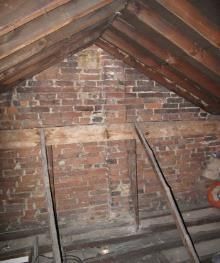
1. INTRODUCTION

This Best Practice Guide has been produced to provide independent generic guidance on the application,
installation, and commissioning of PIV units in existing homes.

Different regions of the UK have different regulatory, compliance and guidance documents in relation to
residential ventilation. It is impractical to cater for all parts of the UK in this guide. As the vast majority of the
UK’s existing housing stock is in England this guide is based around the various documents that apply in
England in relation to the ventilation of buildings.

For residential ventilation work in Scotland, Wales and Northern Ireland this Code of Practice will provide a
good source of advice and information. It should however be noted that in all cases the requirements of the
individual countries Building Regulations and/or any local building bylaws must be observed, and where
necessary the advice of the Local Authority Building Body should be taken.

It is important to note that this guide relates solely to the provision of PIV units into existing homes. For the
purposes of this document new build applications are omitted in their entirety.

This document should be read in conjunction with the PCA Code of Practice for Investigation and Provision
of Ventilation in Existing Dwellings which sets out the general criteria for the assessment of condensation
and ventilation within Existing buildings.

2. DEFINITIONS

For the purposes of this document, the definitions in The PCA Code of Practice for the Investigation and
Provision of Ventilation in Existing Dwellings, BS 6100: Part 5 and Building Regulations Approved Document
F apply with the following amendments/additions:

    •   Background Ventilator
        For the purpose of this document, this is a small, manually, or automatically controlled ventilator
        e.g., a trickle vent in a window or a wall grille. For the avoidance of doubt, it must be a ventilator
        that can open/close.
    •   “Cold roof” space (loft)
        A common UK roof construction method where the insulation is laid between the ceiling joists (i.e.,
        over a normal flat ceiling). During the heating season the roof structure above the insulation is
        colder than the living space.
    •   Cold side ducting
        Ductwork carrying cold air being drawn from an external source to the PIV unit.
    •   Diffuser
        A diffuser is the ceiling or wall mounted grille that allows the incoming air to enter the living space in
        a central area of the property (e.g., the hallway or landing) from the PIV unit.
    •   Open-flued Combustion Appliance
        One which draws its combustion air from the room or space within which it is installed, and which
        requires a flue to discharge its products of combustion to outside. Approved Document J gives
        examples and further information.

                                                                                                                    3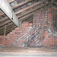
•   Positive Input Ventilation (PIV)
        The principle of providing a continuous supply of fresh air centrally to a home to dilute, displace and
        replace the contaminated air in a home with better quality external air.
    •   Positive Input Ventilation (PIV) Unit
        A ventilation unit and associated components which can be mounted in a property or in the roof
        space (loft) above it which are specifically designed to ventilate a home using the principle of
        Positive Input Ventilation. PIV units are available which can draw air in via a “cold roof” space (loft)
        directly from outside via a system of ducting or a combination of both.
    •   Roof space heat gain
        PIV units which draw external air in via a “cold roof” space (loft) can take advantage of tempering of
        the incoming air as a consequence of solar gain and heat loss from the rooms below. It is estimated
        this roof space heat gain can result in a PIV unit typically supplying air to a home which is on average
        3 degrees centigrade warmer during a typical heating season than if the air was supplied or drawn
        into a home directly from outside as would be the case with air entering through background
        ventilators (e.g., trickle vents) or windows. Building Research Information Paper IP12/00 provides
        useful information on this roof space heat gain.
    •   Solid Fuel Burning Appliance
        For the purposes of this document, it is an open-flued combustion appliance which burns a solid fuel
        derived from plants and trees. This can include wood logs, wood chips, wood pellets, compressed
        paper, coal, charcoal, peat, and processed plant material.

3. SURVEYING INSTRUMENTS

How PIV Works
PIV works by continually diluting, displacing,
and replacing indoor air with filtered, low
moisture content external air from the loft of
an external source. This air is delivered to a
central point in a property and, in turn, each
room off this central point benefits. PIV
systems are adjustable, so the amount of
ventilation they provide can be adjusted to the
amount of moisture being produced or the size
of the home.

PIV systems come in two main forms, loft mounted, and wall mounted. Whilst it can be a very effective
method of ensuring a continuous air exchange within a property, the surveyor and the occupant must be
made aware of its limitations and must acknowledge that in many instances it must be considered as part of
a ventilation system and not used in isolation.

In the vast majority of existing homes the air supplied by a PIV unit will exit via the myriad of small gaps in
the building structure. Background ventilators (e.g. trickle vents in windows) will only be required in
extraordinarily airtight homes. If in doubt about this, please seek specialist advice.

As with any ventilation system, appropriate Purge Ventilation measures are required with a PIV system.
Please refer to Approved Document F for further information.

                                                                                                              4
PIV is classified under Approved Document F of the Building Regulations 2010 (As Amended) as an
alternative ventilation strategy.

Loft mounted PIV unit
A loft mounted PIV unit works by drawing air continuously from a well-ventilated loft space and delivering
this air into the house via a ceiling mounted diffuser. It will have typically 3 to 5 degrees solar gain by being
in the loft space. The air that is forced into the living space is filtered to remove particles e.g. pollen.

The fresh filtered supply air simply dilutes, and displaces the existing air, improving indoor air quality and
managing moisture levels within the home.

Wall mounted PIV unit
The principle of PIV also works for homes without a loft. In the same way fresh air is taken from the loft
space, air can be taken from ducting through an external wall and then fed into the property. They can also
be used to ventilate basements, cellars and other areas that would benefit from a continuous supply of air.
The PIV unit is usually situated in a convenient location, such as a kitchen cupboard or hallway, and is ducted
to a central location.

The diffuser of a wall mounted PIV unit is usually installed at high level in a central location within the
hallway, although discharging the air down the length of the hallway (away from the front door) should also
prove acceptable. It should be noted that as the air is coming from outside then through ducts to a central
diffuser, the duct run itself may need to be boxed in. Thermal ducting should be used where appropriate to
avoid issues of condensation on the duct itself.

                                                                                                               5
PIV unit performance may be enhanced if an existing heat source can warm the discharged air e.g., by
locating the diffuser above a radiator.
PIV unit heaters
PIV units can include integral heaters for tempering the air. This is not a heat source and is only used to
temper incoming air from outside.
Specific Fan Power limitations for PIV units
For regulatory compliance under current Approved Document L1B, a PIV unit’s Specific Fan Power at design
airflow (i.e. taking into account any filters, heater, ducting, diffuser, or grilles connected to a PIV unit) should
not exceed 0.5 W/(l-s).
4. INSPECTION CONSIDERATIONS
When inspecting a structure to determine whether there is a ventilation problem, it is essential to consider
the possible presence of other sources of dampness. Even if the instructions given are limited to the
detection of atmospheric dampness, other problems should be highlighted if they are present and
reasonably obvious to a specialist surveyor.
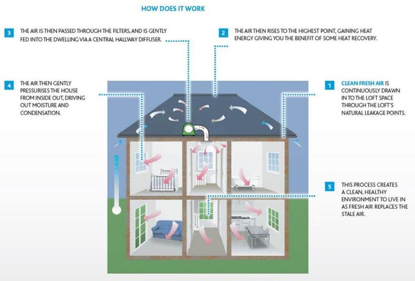
The primary focus of the survey when investigating internal atmospheric moisture related problems should
be to determine what is out of balance within the internal environment and resulted in the problem i.e.
mould growth or condensation.
Further information on the practice of undertaking surveys can be found in the ‘Code of Practice for the
Investigation and Provision of Ventilation in Existing Dwellings’ and Best Practice Guidance Surveying
of Ventilation in Existing Residential Dwellings.
Once it has determined that additional ventilation is required, the surveyor must consider which options are
suitable for the property and occupants. This section details inspection considerations when specifying PIV
units.
The property type
One of the first considerations should be the property type and size. This will have a significant impact on
whether a PIV system is suitable. Properties without central hallways or with remote wet rooms may not be
suitable for PIV systems or may require additional enhancement extract fans. The possible addition of such
fans will be covered in detail later in Section 7 of this document.
If the property is or is part of a building that has a storey 18 metres or above ground level, additional careful
design consideration is required due to the complex nature and health and safety implications of such
installations. If considering a PIV unit installation in such a property, seek specialist advice.
If a PIV unit is being considered to supply air into or via a protected escape route (defined here as a
protected stairway or protected lobby that a front door of a property opens on to and does not part of the
individual property itself) seek specialist advice for such applications as there may be a need for fire and
smoke dampers as well as interlinks with a smoke detection system.
6Wall mounted PIV unit with a ducting system penetrating the hallway wall in a flat
It is not always possible to determine if a hallway wall within an existing flat is fire rated or not. For safety
reasons, the incorporation of a mechanical or intumescent fire damper within the duct penetrating the
hallway wall is highly recommended to be fitted in all cases. Any gaps between the outside of the duct and
the hole in the wall should also be sealed with intumescent mastic. Fire collars which wrap around the
ducting can also be used instead of dampers within the ducting.
3+ storey properties and properties with a storey 4.5 metres or above ground level
There is a requirement to protect a stairway in a property where any floor within it is 4.5 metres or above
ground level or is a 3+ storey building. The reason for this is to allow those on the 2nd floor and above the
time to get down the stairs and out of the building to safety. With this in mind, it means that in such
properties there are special diffuser and smoke detectors interlink requirements. Seek manufacturers
and/or specialist advice for such applications.
Where to diffuse the incoming air on a wall/non-loft PIV
With any PIV installation, it is vital that the incoming air is introduced at a central point within the property.
A central hallway is normally where air should be diffused. If air is diffused incorrectly or solely into a room
directly where there is an issue, the solution will not be fully effective.
Important additional checks
When carrying out your survey you must assess the feasibility of the particular installation location or route.
It is important to find a location which would not be too close to lintels, pipes, or boiler flues. As a wall
mounted PIV unit brings air into the property, the distance between the proposed incoming air flow and
boiler flue must be 1,000 mm or greater. If the inlet is above a boiler flue then the distance needs to be 3000
mm or greater. Equally, if installing an extractor fan, the distance between the proposed air outlet and boiler
flue must be 300 mm or greater. This ensures no products of combustion from the gas boiler ingress through
the extractor fan outlet. For oil fired boilers the distance between the outlet and boiler flue must be a
minimum of 400 mm or greater.
Ensure enough space is allocated when proposing the drilling of a core hole. If drilling a core hole next to a
window there needs to be a gap of at least 150 mm between the edge of the core hole and the window.
This is to ensure the structure of the property remains sound.
With loft installations the loft access hatch should be checked to ensure it is large enough for the installer/s
and the PIV unit to pass through. The loft space should be inspected to ensure there is as little air leakage
into the roof space from any adjacent roof spaces (e.g. in terraced and semi-detached homes) and from the
rooms below as possible.
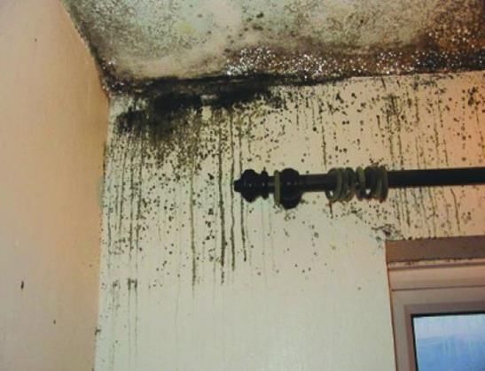
When considering the possibility of installing a loft mounted PIV system into a terraced or semi-detached
property, there should be a party wall in the loft area and it must be fully intact. Any PIV unit installed must
not be commissioned until it is as it could spread smoke and fire from one property to the other. If an intact
party wall is not achievable, seek specialist advice before proceeding.
7Incomplete party wall (left) and complete (right)
When specifying a loft PIV unit ensure the loft area is not airtight as this will prevent the system from
bringing in sufficient fresh external air and working effectively. The presence of daylight is often a good
indication of sufficient leakage. Additional ventilation of the roof space may be required in very tight roofs
e.g. voids with tightly fitted breather membranes.
When establishing the suitability of a loft mounted PIV unit checks are needed to ensure that there are no
ceiling leakages. For example, a poorly sealed loft hatch or uncapped spotlights may cause moisture
migration into the loft. If any of these scenarios are present, then moisture from within the property may
rise through these leakage areas and subsequently enter the loft and be brought back into the property via
the positive input ventilation unit located in that loft area. As such, a cyclical effect will occur thus reducing
the effectiveness of the ventilation system.
Ensure there is no evidence of any vermin or bats in the loft area. If the presence of either is suspected,
then the relevant advice should be sought.
Asbestos Containing Materials (ACMs)
Where the fabric of a building will be disturbed by the installation of any part of a ventilation system,
including but not limited to the fan unit, ducting, diffuser, grilles, wiring and controls, a risk assessment shall
be carried out in accordance with the requirements of the Control of Asbestos Regulations 2012 and any
actions recommended should be complied with.
Textured Decorative Coatings (e.g. Artex) is one of the most common asbestos containing materials that
may be disturbed during a ventilation system installation. The surveyor and installation team must have a
level of training and competence in relation to ACM’s appropriate to the type of work they do.
Open-flued Combustion Appliances
Enhancement extract fans are sometimes installed along with a PIV unit in a home (See “Section 7
ENHANCEMENT EXTRACT FANS” for details). Extract fans can lower the pressure in a building which can
cause the spillage of combustion products from open-flued combustion appliances. Under no circumstances
should an extract fan be installed in any room containing a solid fuel burning appliance.
8Extract fans installed in other rooms containing an open-flued combustion appliance should have a
maximum extraction rate of 20 l/s. See note in Section 8 - COMMISSIONING regarding the testing necessary
when installing extract fans in homes with open-flued combustion appliances.
5. OCCUPIER ENGAGEMENT
The way the system works should be explained to the occupier at the survey stage and should also be
reinforced during the installation process. This is equally important for homeowners and tenants (social &
private housing) alike.
Items that should be explained in detail are:
Maintenance
All manufacturers have air filters on their units. The industry norm is for these filters to last for a period of 5
years, though some may be less. The client should be made aware of the maintenance requirements at the
report stage.
Heaters
Loft and wall mounted PIV units can contain heaters (usually between 400 – 500 Watts). These heaters are
designed to temper the incoming air during cold weather.
It is important that the occupier is made aware that the heater function is not designed to act as a
replacement for any part of the heating system of the property and that when in operation the heater
element will increase the running costs of the unit.
During colder weather, the unit will cool the area around where the diffuser has been fitted. The diffuser is
fitted to these areas generally because it is the most central point in the property to allow it to control any
condensation problem to the maximum amount of rooms in the property, and also because it is the part of
the property in which the occupants spend the least amount of time.
This issue generally only affects properties with small hallways or landings and normally only during
exceptionally cold weather. It should also be noted that this is less likely to be an issue with a well-designed
and correctly commissioned PIV installation.
The occupier should be made aware that the unit’s speed settings can be adjusted post installation. The
occupier should also be notified that the units should not be switched off for any length of time except for
servicing and maintenance.
If the need for a PIV unit to be left on continuously or any other limitation of PIV is likely to be an issue to
the occupants, it may be worth considering an alternative ventilation strategy.
Single glazing
In cold periods, due to the poor thermal efficiencies of single glazed windows, the condensation problem on
windows may reduce slightly but condensation on windows may still occur. The client should be made
aware of this.
96. INSTALLATION
Manufacturer installation instructions must be followed in full. Failure to follow instructions properly can
result in poor performance and may put the occupants and the structure at risk. It is also likely to invalidate
the manufacturer’s warranty and absolve them of any liability. The installation guidance notes which follow
are in addition to those supplied by the manufacturer. Where there is conflict between these notes and
manufacturer’s instructions, then the manufacturers’ instruction should take precedence.
Any PIV unit should only be installed by technically competent and qualified personnel in accordance with all
regulatory requirements.
Any supporting fans should be ducted to the outside and not directly into the roof space. The roof space
access hatch should be insulated and draught stripped, and any other ceiling penetrations sealed as much as
possible to prevent movement of the house air into the roof space and recirculated by the PIV unit.
PIV units which draw in air directly from outside, e.g. wall mounted units or loft units ducted to external
walls due to an airtight loft, should have an inlet grille located well away from any flue discharge, extract fan
discharge, drainage vent or any other potential source of polluted air as described earlier in this document.
Such inlet grilles should be of a low resistance type and should not be fitted with fly mesh as they can
substantially reduce airflow which in turn will decrease the performance of the unit considerably.
Very careful consideration should be given to positioning the PIV unit’s supply air diffuser in relation to
smoke and carbon monoxide detectors. If in any doubt, the specific manufacturer should be contacted for
guidance.
Where any component of a PIV unit passes through a fire resisting wall/floor then appropriate measures
must be incorporated by the installer to ensure the fire resistance of the structure is maintained in the event
of fire. Such measures may include intumescent collars, inserts or fire dampers.
If a PIV unit is being provided to supply air into or via a protected escape route (defined here as a protected
stairway or protected lobby that a front door of a property opens on to and does not part of the individual
property itself) the installer must comply in all respects with the specialist’s instructions in relation to such
works.
Location of the unit (Loft version)
1. The loft unit should be located in the loft space at least 150 mm away from any loft insulation or other
items in the loft, above the central hall and in such a location to minimise the overall duct length and bends.
2. The loft unit should be installed to allow sufficient space to undertake routine maintenance of the unit as
appropriate.
3. The installer should refer to the manufacturer’s installation instructions for detailed guidance.
4. The loft diffuser needs to be positioned in the central hallway.
5. Diffusers or grilles supplying air into a home should be fitted a minimum of 1000 mm away from a central
heating thermostat.
6. Diffusers or grilles supplying air into a home should be fitted a minimum of 1000 mm away from any
smoke of CO detectors. If this is not possible seek specialist advice.
10Where to diffuse the air from a wall mounted PIV
1. With any PIV installation it is vital that the incoming air is introduced at a central point within the
property. The air should be delivered via the diffuser into a central hallway. If this cannot be achieved,
performance can be compromised, and client should be made aware.
2. Diffusers or grilles supplying air into a home should be fitted a minimum of 1000 mm away from a central
heating thermostat.
3. Diffusers or grilles supplying air into a home should be fitted a minimum of 1000 mm away from any
smoke of CO detectors. If this is not possible seek specialist advice.
Inlet ductwork and location of a wall mounted PIV
Condensation can occur on the inlet ductwork of a wall mounted PIV (the ductwork from outside the home
to the wall mounted PIV). As a result, this may need insulating and/or boxing in. Careful consideration
should be given to the location of the wall mounted PIV in order to minimise any inlet ductwork.
Internal door undercuts clearance for air transfer
For a PIV System to be fully effective it is recommended that clearances under doors achieve a minimum
free area of 7,600 mm2 (i.e. a minimum of 10mm under a standard 760 mm wide door) to encourage good
air flow in accordance with Approved Document F Means of Ventilation. This is similar to the air transfer
requirements for all ventilation systems in Approved Document F. If such a door undercut is not possible
then air transfer grille of a similar free area can be used. For fire doors without sufficient undercut please
seek specialist advice.
7. ENHANCEMENT EXTRACT FANS
The installation of a PIV unit alone will help tackle a condensation dampness problem and improve indoor
air quality in any home. Like any ventilation system it is not however a panacea and occasionally the
addition of continuously running enhancement extract fans in “Wet Rooms” such as kitchens, utility rooms,
bathrooms, en-suites, and WCs may be necessary to optimise performance. The installation of an
enhancement extract fan is highly recommended in the following Wet Rooms:
1. Any Wet Room which does not have an openable window or door to outside.
2. Any Wet Room where the air from a PIV unit or units would have to pass through another Wet Room to
get to it.
3. Any Wet Room where the air from a PIV unit or units would have to pass through it to get to any
“Habitable Room”.
Enhancement extract fans should be set to a background airflow setting of 4-6 l/s and should also be
capable of the following boost rates:
Kitchens – 13 l/s.
Utility rooms, bathrooms, and en-suites – 8 l/s.
WCs – 6 l/s.
If there is an existing intermittent extract fan installed in any of the aforementioned Wet Rooms, it is highly
recommended that it is replaced with an enhancement one as above. If there is an existing continuously
running extract fan it is highly recommended that its airflow settings are adjusted to those above.
11Other extract fans in other Wet Rooms are unlikely to have an adverse effect on a PIV system, however, it
important to note that the total background airflow of all continuously running extract fans should not
exceed 40% of the Normal Airflow Mode setting of the PIV unit.
8. COMMISSIONING
As required under Approved Document F, if a PIV unit can be tested and adjusted, it must be commissioned
and a commissioning notice given to the local Building Control Body (BCB). This also applies to any
enhancement extract fans that may be installed with a PIV unit which can be tested and adjusted. It is not
necessary to notify a BCB in advance if the work is completed by a person registered with a Competent
Person Scheme that covers such work. Approved Document F gives much more detailed information on this
notification process and reading and understanding of this process is highly recommended.
It is vital that a PIV unit is commissioned properly to prevent over or under ventilation of a home and to
ensure that the unit is optimised to perform to the best of its capability. This normally involves setting the
various modes for the specific unit being installed. Most units require the PIV unit to be installed and
electrically connected before the various mode settings can be set. However, there are some PIV units
where the mode settings can be set before the unit is installed or electrically connected which then operate
the unit at the desired settings when it is installed and electrically connected.
When the PIV unit and enhancement fans have been commissioned, the person commissioning them should
spend time with the home occupants explaining how they work, what they should expect by way of
performance and what maintenance will be required. They should also provide the occupants, and the
homeowner if different, with hard copies of operational and maintenance information on the equipment
installed.
Normal airflow mode setting
The steps which follow are based around those in Approved Document F with increased or decreased
airflows depending on each individual property.
Step 1 Estimate airflow rate in litres/ second (l/s) based on occupancy level (count a large dog as 1
occupant and a small dog and cat as ½ occupant each)
1-3 occupants = 17 l/s
4 occupants = 21 l/s
5 occupants = 25 l/s
6 occupants = 29 l/s
7 occupants = 33 l/s
8 occupants = 37 l/s
9 occupants = 41 l/s
10 occupants = 45 l/s
Step 2 Estimate airflow rate based on total internal floor area
Total internal floor area in m2 x 0.3 = l/s.
12Step 3 Take the higher rate of Step 1 or 2 = l/s
Step 4 If necessary, add the following flow rates to the airflow rate in Step 3
Add 4 l/s for a poorly insulated property (e.g. single glazing, un-insulated walls, and ceilings)
Add 4 l/s for higher than typical moisture production in property (e.g. excessive indoor clothes drying, high
levels of cooking activity, bottled gas heater, fish tanks, etc.)
Final Estimated Airflow Rate = l/s.
Step 5 Check/compare Final Estimated Airflow Rate to occupancy level i.e.
Final Estimated Airflow Rate l/s ÷ occupancy level = l/s per occupant (Occupancy Ratio).
If Occupancy Ratio is greater than 20 l/s per occupant, please contact a PIV specialist for advice on whether
or not a lower Final Estimated Airflow Rate than that in Step 4 is recommended.
Step 6 Set the PIV unit to the nearest Normal Airflow mode rate setting equal to or greater than the Final
Estimated Airflow Rate in Step 4 or other reduced rate as Step 5 above. To avoid excessive ventilation and
consistency with Approved Document L1B, the Normal Airflow mode rate setting of the PIV unit should not
be set more than 4 l/s higher than the Final Estimated Airflow Rate.
Enhancement extract fans fitted with a PIV unit
Performance enhancing extract fans installed at the same time as a PIV unit in a home should also be
commissioned properly, in accordance with manufacturer’s instructions and by technically competent and
qualified personnel in accordance with all regulatory requirements.
Where extract fans are installed in a property containing an open-flued combustion appliance or appliances,
the extract fans should be temporarily electrically isolated following installation and commissioning by the
ventilation installer. Tests by appropriately qualified persons to show that the combustion appliances can
operate safely whether or not the fans are running should be carried out as soon as possible after the
ventilation installation. These tests should be done with the PIV unit off and all the extract fans on at
maximum extraction rates. This testing regime will require the persons carrying out the tests to temporarily
switch the power supply to the extract fans back on and the power supply to the PIV unit off. The extract
fans and the PIV unit should only be permanently re-energised once the tests have been completed
satisfactorily.
9. OPERATIONAL MODES
This section details the various operation modes of PIV units available from various PIV manufacturers.
Normal Airflow mode
This is the mode that a PIV unit will run at for the vast majority of its operational time. It is this airflow
setting which needs to be set carefully at commissioning stage to suit the individual requirements of the
property. Some PIV units incorporate sensors and controls to optimise airflow and switch the unit between
Normal Airflow mode and other modes including Heat Recovery mode, Moisture Content Control mode and
Standby mode. Some units also have an Override Boost mode activated manually by the occupants via a
switch or via sensors located in the living space.
13Heat Recovery mode
A control function which increases the PIV unit’s airflow when the loft temperature reaches the Heat
Recovery mode trigger temperature, with the intention to supply additional warmed air into the home. PIV
units are available with fixed or adjustable airflow increase percentages and fixed or adjustable heat
recovery mode trigger temperature settings.
This mode may not be available on some PIV units. Units with this feature have either a factory set and fixed
Heat Recovery mode trigger temperature (typically 19 degrees centigrade) or an adjustable trigger
temperature. It is recommended that PIV units which can be adjusted have the trigger temperature set to 1
degree centigrade above the average temperature the surveyor/installer thinks the area of the home the
unit will supply air into will be heated to. PIV units are also available with fixed or adjustable airflow increase
percentages.
Comfort Control mode
A control function designed to reduce the airflow of a PIV unit when the incoming air temperature is
undesirably high. This mode is often considered as an alternative to Heat Recovery mode functionality.
Standby mode
A control function designed to switch a PIV unit off when the incoming air temperature reaches the Standby
mode trigger temperature to save energy and prevent undesirable warm air being introduced unnecessarily
into the home e.g. during hot summer days. PIV units are available with fixed or adjustable Standby mode
trigger temperature settings. If continuous running of a PIV unit is required, for example if a PIV unit is being
used to control radon gas in a home, then this function should be disabled or a continuous running PIV unit
without this function should be installed.
This mode may not be available on some PIV units. Units with this feature have either fixed Standby mode
trigger temperature (typically 25 degrees centigrade) or an adjustable trigger temperature which can be set
to switch the unit off at higher or lower loft temperatures.
Hygrothermal Control mode
A control function which monitors the PIV unit’s incoming air temperature and moisture content and
regulates the units’ airflow accordingly when incoming air temperatures and moisture contents are low.
PIV units with this function normally allow the installer to enable or disable it as required.
Override Boost mode
A function where the PIV unit’s automatic controls can be overridden to operate the unit at its maximum
airflow by means of a manual user control or automatically via sensors in the living space (e.g. humidity and
CO2 sensors).
Manufacturer instructions should be followed if this mode is to be used.
1410. LEGISLATION
The following legislation is referred to in this document:
• Building Regulations Approved Document F
• Building Regulations Approved Document L1B
• The Health and Safety at Work etc. Act 1974
• Control of Asbestos Regulations 2012
Employers and employees should satisfy themselves that they have knowledge of the duties placed on
them by all relevant legislation.
11. ACKNOWLEDGEMENTS
The PCA would like to thank all those who contributed to the production of this guide and in particular the
following for the time and effort they put in to it:
• Homevent – A division of Elta Fans
• Envirovent
• Nuaire
For further information, contact:
Property Care Association
11 Ramsay Court
Kingfisher Way
Hinchingbrooke Business Park
Huntingdon
Cambs.
PE29 6FY
Tel: Tel: 0844 375 4301
Fax: 01480 417587
Email: pca@property-care.org
Web: www.property-care.org
The Property Care Association incorporating the BWPDA is a company limited by Guarantee: Registered No. 5596488 England
©Property Care Association, June 21. All rights reserved.
15You can also read