Green Orca High Energy - Technical Brochure - EST-Floattech
←
→
Page content transcription
If your browser does not render page correctly, please read the page content below
The world’s safest battery system

                 EST-Floattech develops and manufactures state-of-the-art energy storage systems
                 (ESS) for the maritime and land-based industry. The Green Orca® High Energy ESS is
                 our flagship product.

                             The technical design

                             choices for the Green Orca®

                             ESS started with a high
                                                                       CELL               MODULE
              SAFETY         performance Li-Ion battery

                             cell and resulted in the world’s

                             safest, DNV-GL certified Li-Ion

                             ESS.

                                                                BATTERY APPLICATION   SYSTEM ON BOARD
Battery Cells
Lithium Polymer NMC cells by Kokam
Kokam Battery Cells Life time & Cycle Life
Our partnership with Kokam, one of the world’s leading cell manufacturers is a strong Our cells have a Cycle Life 1) of approx. 4,600 cycles 2), and DoD 3) of 80% at an
foundation for our ESS design, in which our state-of-the-art technology is combined EoL 4) of 80%. Based on your operations we can predict the expected lifetime
with Kokam’s patented and certified cell design. for your application with our simulation software.
Lithium Polymer NMC pouch cells
200.000
Our Green Orca Modules use Kokam’s Lithium Ion
Polymer NMC (Nickel Manganese Cobalt Oxide)
pouch cells. The NMC chemistry has a high energy 150.000
density and overall strong performance while
Cycle Life
the pouch shape ensures better heat dissipation 100.000
resulting in excellent efficiency.
50.000
Z-Folding
The unique ‘Z-folding’ cell construction technique
5.000
significantly reduces internal cell resistance and 0% 10% 20% 30% 40% 50% 60% 70% 80% 90% 100%
thus delivers an exceptional cycle life, thermal Depth of Discharge
performance and high discharge rate capability.
1) Cycle Life #: the number of complete charge-discharge cycles a battery can perform by a certain DoD
(see table)
2) At 1C charge and discharge
3) Depth of Discharge % (DoD): the percentage of total capacity that is discharged (see table)
4) End-of-Life % (EoL) indicates the time elapsed before a battery becomes unusable, as the capacity
decreases with use and over timeGreen Orca® high energy modules
Built as one of the industry’s safest modules
Green Orca® Modules Battery Management System (BMS)
By combining Kokam’s leading cell technology with our own mechanical design and battery Our current generation battery management system (BMS) is the
management system (BMS), we created the Green Orca High® Energy Module. The module is safe result of 10 years of continuous development and is essential for safe
by design due to multiple safety layers in mechanical design and software, meeting strict DNV-GL and optimal ESS performance. The key features of the BMS are:
and NMA class requirements. - Continuous, active cell balancing to ensure maximum
system up-time
Mechanical design - High resolution redundant individual cell voltage and
Our mechanical design combined with a patented spring temperature measurements
load construction keep the cells in position under the most - Synchronised wide range current measurement
demanding circumstances. Due to our cell arrangement, - Redundant hardware and software safety layers
we achieve a permanent ultra-low impedance power path
inside the battery module. The base of the module contains Each string of battery modules has a battery control unit (BCU) which
a thermal conductive material allowing extra heat dissipation collects all BMS data and calculates accurate and real-time State
and mechanical robustness. The aluminium enclosure of Charge (SoC), State of Health (SoH) & other ESS information for
prevents ingress of water and dust. optimal system integration.
Energy Modules (C-Ratings, Capacity)
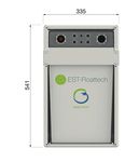
The Green Orca® High Energy Battery Module uses 14 x
200Ah / 3.7V cells, connected in series, resulting in a gross
energy capacity of 10.5kWh and a voltage of 52V. The Green
Orca has a maximum C-rating of 1.5C discharge (300A), and a
maximum charge rating of 1C (200A).Green Orca® Energy Storage System
Marine quality design and integration
Green Orca® Energy Storage System control up to three Slave BCU’s. Interfacing is possible through Modbus TCP
EST-Floattech’s 30+ years experience in marine system (preferred), CAN-bus (NMEA2000) or hardwired 24Vdc I/O. The BCU is powered
integration resulted in a state-of-the-art ESS design and by a redundant 24Vdc supply and has pre-charge functionality built in, making
unparalleled customer service in every step of the ship building start-up from black-out possible
process, from conceptual design to sea trials of the vessel. Our
ESS uses a battery control unit (BCU) for integration with the Modular and adaptable design
ship’s system, is modular and adaptable to different needs and Our modular and adaptable design can meet different mechanical and electrical
purposes and is DNV-GL approved for maximum safety. requirements.
Three main configurations are commonly used in order to integrate the ESS into
Our system is developed for use in maritime applications, such as fully electric or the ship’s power distribution system:
hybrid propulsion (combined with diesel generators, hydrogen or LNG power systems).
In diesel-hybrid applications peak shaving can reduce generator size and increase
efficiency. Our ESS can also be used for hotel loads or auxiliary equipment power.
Battery Control Unit (BCU)
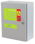
The Battery Control Unit (BCU) is responsible for communication
between the battery modules and the application’s power
management system. The BCU transforms the separate battery
modules into a state-of-the-art Energy Storage System (ESS) and
adds another layer of hardware and software safety.
The BCU collects and processes al battery module data and has redundant sensors &
safety mechanisms built in. It contains the power electronics necessary for switching
a battery string on or off. The BCU comes in two versions for ease of integration:
The amount of modules in a string depends on AC or DC bus voltage requirements and strings can be
Master & Slave BCU. The Master BCU connects to the ship’s communication and can connected in parallel to meet capacity or redundancy requirements.Safety
Safe under all circumstances
Safety and Certification DNV-GL type approval and NMA compliance
Marine applications need to be reliable and safe and our ESS has been designed EST-Floattech’s Green Orca® High Energy storage system complies with
to assure safety in all circumstances. Li-Ion batteries have an inherent ‘Thermal the RSV12-2016 propagation test of the Norwegian Maritime Authority
Runaway’ risk due to the amount of chemical energy stored inside the battery (NMA), and requirements of DNV-GL. Our DNV-GL type approval means less
cells. Our ESS includes multiple safety layers for prevention and our passive safety requirements for the battery room.
system offers protection in the rare occurrence of a thermal runaway.
Prevention with hardware & software
Li-Ion ESS, just like diesel tanks for example, have a high amount of chemical
energy stored inside. When a Li-Ion battery (cell) reaches certain temperatures, a
thermal runaway event can happen where this chemical energy is rapidly released
in the form of hot gasses. A thermal runaway needs to be prevented and contained
should it ever happen. The building blocks of our ESS, the BMS and BCU, contain
intrinsic, redundant hardware and software safety systems and processes. They
prevent the Li-Ion battery cells of reaching these critical limits.
Passive safety system
Our safe by design philosophy resulted in a passive safety system thanks to our
integrated exhaust system which funnels thermal runaway-gasses to a safe
location outside the battery room. Aluminium battery housing and fire retardant
insulation between battery modules prevent the propagation of a thermal runaway-
event to other modules.Technical specifications
Green Orca® High Energy Battery Cell Tests
Capacity 10,5 kWh UN38.3 T-2 Thermal abuse
Cycle Life at 80% D.O.D and 80% E.O.L. >4.600 cycles at 1C charge/discharge UN38.3 T-5 External Short Circuit
Cycle Life at 50% D.O.D and 80% E.O.L >20.000 cycles at 1C charge/discharge UN38.3 T-6 Impact
Cycle Life at 20% D.O.D and 80% E.O.L >75.000 cycles at 1C charge/discharge UN38.3 T-8 Forced Discharge
Max Charge 200A/1C Overcharge (by the redundant safety system)
Max Discharge 300A/1.5C
Module Voltage Minimum 45V
Module Voltage Nominal 52V
Battery System Tests
Module Voltage Maximum 58V Propagation Test
Balancing Type (BMS) Continuously Active Balancing Safety function test – Emergency stop function
Certification DNV-GL Type Approval Capacity Validation
NMA Level 1 Propagation Approval Sensor Loss
Dimensions (W x H x D) 335 x 541 x 542 mm State of Charge Validation
Communication ModBus, CANbus or Hardwired I/O IEC 62619 Overcharge with Voltage
Allowed Current Ripple 5% peak to peak max IEC 62619 Overcharge with Current
Weight 82 kg. IEC 62619 Overheating Control
Cooling Air Cooled IEC 61000-4 EMC
Gas Exhaust System Stainless steel
Racking Aluminum
Dedicated Battery Room Required by Class
Environmental Tests
DNV-GL CG0339 Vibration
DNV-GL CG0339 Dry Heat
DNV-GL CG0339 Damp Heat
DNV-GL CG0339 EMCSubject to printing, typesetting, and typing errors. Specifications can change without prior notice. HEADQUARTERS NORDIC OFFICE Zandsteen 1, 2132 MZ Hoofddorp, The Netherlands Bolerveien 60, 2020 Skedsmokorset, Norway +31 (0) 227 570 057 | info@est-floattech.com | sales@est-floattech.com | www.est-floattech.com +47 (0) 913 35760 | info@est-floattech.com
You can also read


