EV Charging Solutions - Supercharged Solutions to Enhance Safety, Efficiency, and Reliability - Littelfuse
←
→
Page content transcription
If your browser does not render page correctly, please read the page content below
EV Charging Solutions
                                                                                   Supercharged Solutions to Enhance
                                                                                   Safety, Efficiency, and Reliability
                                                                                          EV Infrastructure

    Users must independently evaluate the suitability of and test each product selected for their own specific applications. It is the User’s sole responsibility to determine fitness for a
    particular system or use based on their own performance criteria, conditions, specific application, compatibility with other parts, and environmental conditions. Users must
    independently provide appropriate design and operating safeguards to minimize any risks associated with their applications and products. Littelfuse products are not designed
    for, and may not be used in, all applications. Read complete Disclaimer Notice at littelfuse.com/disclaimer-electronics.

REV0921
Types of electric vehicle charging stations
      AC Level 1*                            AC Level 2*                                    DC Fast Charger*            Wireless Chargerǂ

       Basic home                          Home and public                                Public and commercial           Home and public
       installation                          installation                                       installation                installation
    (Mode 1 or Mode 2)**                         (Mode 3)**                                          (Mode 4)**

         Voltage                             Voltage                                             Voltage                    Power levels
    120 V AC, 1-phase                208 V–240 V AC, 1-phase                             380 V–600 V AC, 3-phase           WPT1 − 3.7 kW
    250 V AC, 1-phase                   250 V AC, 1-phase                                                                  WPT2 − 7.7 kW
    480 V AC, 3-phase                   480 V AC, 3-phase                                                                  WPT3 − 11 kW

      Current rating                         Current rating                                   Current rating           Grid to battery efficiency
12 A–16 A (32 A for 3-phase)                  12 A–80 A                                    DC output (up to 400 A)   94% at a 10″ ground clearance

      Charging time                          Charging time                                       Charging time        Vehicle ground clearance
      8–12 hours***                           4–6 hours***                                         30 mins***         100−250 mm (3.9″ to 9.8″)

                                  * As defined by SAE J1772
                                 ǂ As defined by SAE J2954
                                ** As defined by IEC 61851-1                                                                       Littelfuse, Inc. © 2021   2
                               *** Charge time dependent on vehicle’s battery capacity and charge acceptance rate
Global electric vehicle charging equipment market
Market trends and drivers Rapid growth of EV Charging at ~36% CAGR
50
Increasing production of electrified vehicles: estimated 6 million vehicles in
2019 growing to 40 million vehicles in 2025 need for higher efficiency 40
Million units
7.3 million chargers are active across the world (as of 2019), of which, nearly 30
6.5 million are private chargers, 0.6 million are public slow chargers, and 0.26 20
million are public fast chargers
10
Currently, more than 70% of the charging is done at home. Convenience, cost-
efficient, and a variety of support policies are the main driving. 0
2019 2020 2021 2022 2023 2024 2025
Majority of charging to occur at home or workplace during a span of several
hours (AC charging) bidirectional topologies is needed for smart grid
EV charging equipment, by type, in 2019
Limited charging grid capacity in most regions Emergence of combo
ESS+PV with DC charger 1%
2% 7%
Increasing voltage and power output of DC chargers
for fast charging 500 V to 800 V
Low-power DC charging solution in residential/campus will replace the AC
charging solution to make charging faster (20 kW DC versus 7 kW AC) 90%
DC charger create a need for improved safety and additional components, such
as advanced liquid-cooled cables, substations, and energy storage systems AC Level 1 AC Level 2 DC Charging Wireless Charging
Source: IEA Report Global EV Outlook 2020; DC Fast Charging; Modor Intelligence;
Statista Report; Littelfuse estimates
Littelfuse, Inc. © 2021 3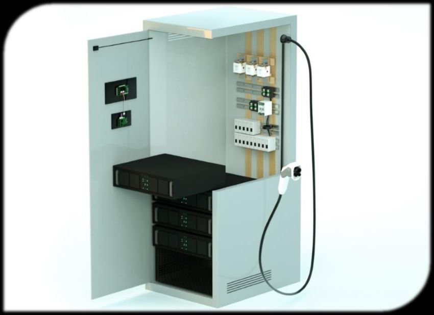
AC charging station
1    Service Access Panel                     4   User Interface
⚫ Reed Sensor                                 ⚫ TVS Diode Array
                                              ⚫ Polymer ESD Suppressor
                                  1
                                          4

2    Input Protection                         5   Communication
⚫   Fuse                                      ⚫ TVS Diode Array
⚫   MOV                                   5   ⚫ Reed Relay
⚫   GDT
⚫   TVS Diode
                              2       6       6   Charging Plug
3    Auxiliary Power Supply
                                              ⚫ Temperature Sensor
⚫ PPTC                                        ⚫ Reed Sensor
⚫ Schottky Diode
⚫ SIDACtor® + MOV

                                  3           7   AC Relays/Contactor
                                      7
                                              ⚫ Contactors & Relays

                                                                         Littelfuse, Inc. © 2021   4
Click on the product series in
the table below for more info
AC charger functional block diagram
Technology Product series
AC output
1 7 High-current Fuse
AC 606
(Primary protection)
input Power Output
Input AC relays/ Current Surge protection
distribution SPD Type 2
protection contactors sensor (Primary protection)
unit
Fast-acting or Time lag Fuse
1 314, 324, 215
(Secondary protection)
Metal-Oxide Varistor TMOV, UltraMOV
2 6 Gas Discharge Tube CG2, CG3
Auxiliary Charging plug TVS Diode AK6, 1.5SMC
power supply Controllers
position/temp
PPTC LVR**
2 Schottky Diode DST, DSA, DSB
3 4 5 SIDACtor + MOV Pxxx0FNL + UltraMOV
Access panel TVS Diode Array AQ24CAN, SM712
Communication User interfaces
Wireless sensors 3
Reed Relay HE3600
TVS Diode Array SP1026
CAN Bus 4 Polymer ESD XGD10402
Legend: 5 Reed Sensor 59060, 59045
Power
PPG, USW,
Data Temperature Sensor
6 Glass Coated Thermistor
Reed Sensor 59060, 59045
HCC 1 & 2 Pole,
Contactors or
7 Relays
HCC 3 & 4 Pole, HCD, or
SCO1*, SCO2*
*Please contact Littelfuse sales for more details
**Only used in case of Linear transformer
Note: Other Littelfuse solutions may be suitable depending on design-specific requirements
Littelfuse, Inc. © 2021 5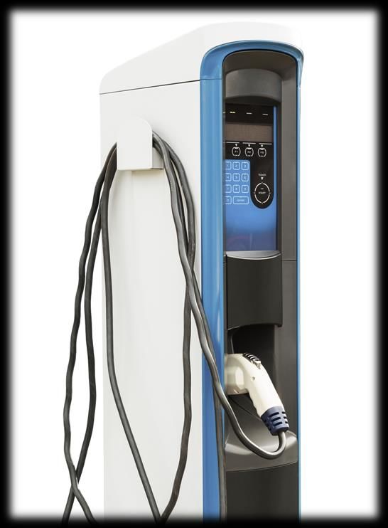
Click on the product series in
the table below for more info
Features and benefits of Littelfuse solutions
Technology Function in application Product series Benefits Features
High-current Fuse Primary over-current protection of EV Enables robust yet compact design; can operate in Rated voltage @ 500 VAC; 40−63 A rating available;
606
(Primary Protection) equipment extreme temperature environment small footprint
Surge protection Withstands high-energy transients to prevent 20 kA nominal interrupting rating and 50 kA maximum
Protects from power fluctuations or surges SPD Type 2
(Primary protection) disruption, downtime, and degradation interrupting rating
Fast-acting Fuse Overcurrent protection of auxiliary power Reduces customer qualification time by complying with In accordance with UL Standard 248-14; available in
314, 324, 215
(Secondary Protection) supply third-party safety standards such as UL/IEC cartridge and axial lead format
1 Reduces customer qualification time by complying with High energy absorption capability:
MOV GDT in series with TMOV protects the TMOV, UltraMOV
third-party safety standards such as UL/IEC 40–530 J (2 ms); integrated thermal protection
auxiliary power supply unit from voltage
Small form-factor allows for compact High energy absorption capability;
GDT transients induced by lightning CG2, CG3
system design small form-factor; low leakage current
Protects power line from transient surge Good clamping and fast response time for High power TVS 8/20 µs rating from 1−20 kA in axial-
TVS Diode AK6, 1.5SMC
transient high-energy transient protection lead or SMT form factor
Protected linear transformers from damages Fast time to trip; offers boards space savings; reduces Line voltage ratings of 120 and 240 VAC; low
PPTC LVR**
due to mech overloads, overheating, etc. customer qual time by complying with UL/IEC resistance; holding current up to 2 A; compact size
Reduces switching losses; increases system High surge capability; negligible reverse recovery
2 Schottky Diode Used for rectification DST, DSA, DSB
efficiency, reliability and thermal management current; Tj = 175 °C
Enhancing surge protection for auxiliary Good clamping and fast response time for 3 kA, 8/20 µs surge capability to help protect AC lines
SIDACtor + MOV Pxxx0FNL + UltraMOV
power supply high-energy transient protection from harmful transient surges.
Meets ESD protection levels specified under IEC 61000-
Protects CAN, Ethernet, RS-485 bus from Ensures reliability of the equipment without
TVS Diode Array AQ24CAN, SM712 4-2; ISO10605;
ESD, EFT, and voltage transient performance degradation
3 low leakage current and clamping voltage
Low power switching with up to 2500 V Low power consumption; galvanic isolation; Miniature single in-line package; external magnetic
Reed Relay HE3600
isolation immune to environmental effects shield option
TVS Diode Array SP1026 Smaller form-factor and multi-line protection enables SP1026 has high ESD robustness for touchpads;
4 Polymer ESD
Protects ICs from ESD through display
XGD10402 ease of design XGD10402 has ultra-low capacitance for I/O
Well suited for usage in high-moisture and
Robust in end application; mount directly into PCB;
5 Reed Sensor Access panel for position sensing 59060, 59045
no standby power requirement
contaminated environments; molded stand-off to allow
board washing
PPG, USW, Offers high accuracy; high reliability; Linear relationship between temp and resistance; temp
Temperature Sensor DC contacts hotspot detection
Glass Coated Thermistor excellent stability at high temperatures range -50 °C to +500 °C
6
Robust design; well suited for usage in high-moisture Hermetically sealed, magnetically operated contacts;
Reed Sensor Charging plug position sensing 59060, 59045
and contaminated environment certified tor use in NA and Europe
Predetermined life cycle for application to minimize
HCC 1 & 2 Pole, Long electrical life; High surge capability; Certified for
cost; high electrical and thermal conductivity; good
Contactors or Safety cutoff on the grid (power network) to HCC 3 & 4 Pole, HCD use in North America, Europe and Asia
7 Relays prevent abnormal current supply.
resistance to oxidation for longer life
PCB mount capable; higher flexibility for designers; Low heat generation and low coil power consumption;
SCO1*, SCO2*
compact design; performance to meet regulatory UL/IEC compliance
Littelfuse, Inc. © 2021 6
DC charging station
1    Service Access Panel                                    6    Power Distribution Unit
⚫ Reed Sensor                         1                      ⚫ Fuse
                                                    6
2    User Interface                                          7    Input Protection
                                  2
⚫ TVS Diode Array                                            ⚫   Fuse
⚫ Polymer ESD Suppressor                                 7   ⚫   Surge Protection Device
                                                             ⚫   TVS Diode
3    Communication                                       8   ⚫   Current Transformer
                                                             ⚫   AC Earth Fault Relay
⚫ TVS Diode Array                         3
                                                    10
4    Rectification & PFC                                     8    DC Output Protection
⚫   SiC/Si MOSFET                         4                  ⚫ ⚫ DC Fuse
⚫   Rectifier Diode/Module                                   ⚫ HVDC Contactor
⚫   Gate Driver                                              ⚫ Earth Fault Relay
⚫   Temperature Sensor                                   9
                                              5
5    Rectification & PFC                                     9    Auxiliary Power Supply
⚫   SiC/Si MOSFET            10   Charging Plug              ⚫   Fuse
⚫   Rectifier Diode/Module                                   ⚫   MOV, GDT, SIDACtor® + MOV
⚫   Gate Driver              ⚫ Temperature Sensor            ⚫   Si MOSFET
⚫   Temperature Sensor       ⚫ Reed Sensor                   ⚫   Rectifier Diode

                                                                                           Littelfuse, Inc. © 2021   7
Click on the product series in
the table below for more info
DC charger functional block diagram
Technology Product series
Rectifier & power High-Frequency DC output
factor correction converter 1 AC Fuse (PDU level) JLLS, JLLN
1 2 4 8 10 Overcurrent protection
AC Overload PSR, L50QS, L75QS
input Power Bridgeless, Output (Primary protection)
Input Full bridge, &
distribution vienna or
protection resonant short-circuit 2 Surge protection
unit boost stage SPD Type 2
protection (Primary protection)
TVS Diode AK6, 1.5SMC
Si MOSFET PolarTM
Rectifier and Schottky Diode DMA, DST, DSA, DSB
3 5 9 11
AC Fuse
Auxiliary DC earth-fault 314, 324
Gate drivers Gate drivers 3 (Secondary protection)
power supply protection
Metal-Oxide Varistor TMOV, UltraMOV
6 Gas Discharge Tube CG2, CG3
Current and
voltage 12 SIDACtor + MOV Pxxx0FNL + UltraMOV
monitoring Charging Plug
Controllers Rectifier Diode DMA
Position/Temp
7 Rectifier Module MDD, VUO, MDNA
AC earth-fault SiC/Si MOSFET/
4 Discrete IGBT
LSIC1MO/X2-Class/XPT
protection
13 14 15 Diode LSIC2SD, DHG, DSEI
Access panel
Wireless Communication User interfaces Temperature Sensor USUR1000, KC
sensors
5 Gate Driver IXDN609, IX4351NE
CAN Bus 6 Current Transformer SE-CS30
Note: Power converter topologies may differ based on 7 AC Earth-Fault Relay SE-704
Legend:
design-specific requirements.
Power Note: Other Littelfuse solutions may be suitable depending
Data on design-specific requirements.
Littelfuse, Inc. © 2021 8
Click on the product series in
                                                                                                                                                                    the table below for more info

Features and benefits of Littelfuse solutions
       Technology                 Function in application                  Product series                              Benefits                                             Features
           AC Fuse           Provide fast-acting overload and short                               Reduces damage to equipment caused by heating        Extremely current-limiting; Small footprint
1        (PDU Level)         circuit protection.
                                                                               JLLS, JLLN
                                                                                                  and magnetic effects of short circuit currents;      200 kA interrupting rating
    Overcurrent protection                                                                        Lower I2t performance allows for quick response to
                             Protects semiconductor devices                PSR, L50QS, L75QS                                                           550–1300 VAC, 500–1000 VDC, 40–2000 A
     (Primary protection)                                                                         protect devices from higher heat energy
       Surge protection      Protects from power fluctuations or                                  Withstands high-energy transients to prevent       20 kA nominal interrupting rating and 50 kA
2    (Primary protection)    surges
                                                                               SPD Type 2
                                                                                                  disruption, downtime, and degradation              maximum interrupting rating
                             Protects power line from transient surge                             Good clamping and fast response time for           High power TVS 8/20 µs rating from 1 kA to
         TVS Diode                                                            AK6, 1.5SMC
                             transient                                                            high-energy transient protection                   20 kA in axial-lead or SMT form factor
                                                                                                                                                     Low RDS(ON) and Qg; avalanche rated; international
         Si MOSFET           High-speed switching                                PolarTM          Easy to mount; space-savings; high power density
                                                                                                                                                     standard packages; low package inductance
    Rectifier and Schottky   Provides output rectification in auxiliary                                                                              Low forward voltage drop; high-frequency operation;
                                                                          DMA, DST, DSA, DSB      Improves power supply unit efficiency
             Diode           power supply                                                                                                            high junction temperature
           AC Fuse           Overcurrent protection of auxiliary                                  Reduces customer qualification time by complying In accordance with UL Standard 248-14;
                                                                                 314, 324
    (Secondary protection    power supply                                                         with third-party safety standards such as UL/IEC   available in cartridge and axial lead format
3                                                                                                 Reduces customer qualification time by complying High energy absorption capability:
            MOV              GDT in series with TMOV protects the            TMOV, UltraMOV
                                                                                                  with third-party safety standards such as UL/IEC   40–530 J (2 ms); integrated thermal protection
                             auxiliary power supply unit from voltage
                                                                                                                                                     High energy absorption capability;
            GDT              transients induced by lightning                    CG2, CG3          Small form-factor allows for compact system design
                                                                                                                                                     small form-factor; low leakage current
                             Enhancing surge protection for auxiliary                             Good clamping and fast response time for           3 kA, 8/20 µs surge capability to help protect AC
      SIDACtor + MOV                                                      Pxxx0FNL + UltraMOV
                             power supply                                                         high-energy transient protection                   lines from harmful transient surges.
                                                                                                  Small footprint; multiple package options          Low leakage current and forward voltage drop;
       Rectifier Diode                                                             DMA
                             Converts AC line voltage supplied to the                             (high voltage, isolated, and standard packages)    improved thermal behavior; high robustness
                             drive to DC                                                                                                             Package with DCB ceramic; very low forward
       Rectifier Module                                                     MDD, VUO, MDNA        Compact design, better electrical isolations
4                                                                                                                                                    voltage drop and low leakage current
      SiC/Si MOSFET/
                             Boost converter for high-frequency           LSIC1MO/X2-Class/XPT Optimized for high-frequency applications               Ultra-low output capacitance and on-resistance
       Discrete IGBT
                             switching in the PFC circuit
           Diode                                                           LSIC2SD, DHG, DSEI     Reduces switching losses; increases efficiency       High surge capability; negligible IRR; Tj 175 °C
    Temperature Sensor Temp sensing for semiconductors                       USUR1000, KC         Rapid thermal response and long-time reliability     UL recognized; temperature range: -40−125 °C
                                                                                                  Quick turn-on and turn-off of MOSFETs/IGBTs;         9 A peak current; low propagation delay time;
5        Gate Driver         Controls the switching MOSFETs/IGBTs          IXDN609, IX4351NE
                                                                                                  eliminates the need for separate supply              low output impedance
                                                                                                  Specifically designed for low level detection;
6    Current Transformer
                             Offers ground-fault detection and
                                                                                SE-CS30
                                                                                                  flux conditioner is included to prevent saturation
                                                                                                                                                       Turns ratio 600:1 and current rating 30:0.05 A
                             protection                                                           No calibration; low level protection and system      Microprocessor-based; adjustable pickup (10 mA-5
7   AC Earth-Fault Relay                                                         SE-704
                                                                                                  coordination; low maintenance                        A); Adjustable time delay (30 ms−2 s)

                                                                                                                                                                                     Littelfuse, Inc. © 2021   9
Click on the product series in
the table below for more info
DC charger functional block diagram
Technology Product
Rectifier & power High-Frequency DC output
factor correction converter LSIC1MO, X-Class,
SiC or Si MOSFET
1 2 4 8 10 X2-Class, HiPerFETTM
AC Overload
input Power Bridgeless, Output LSIC2SD, DHG,
distribution
Input Full bridge, & 8 Diode
protection vienna or DSEI
unit resonant short-circuit
boost stage
protection
Temperature Sensor USUR1000, KC
9 Gate Driver IXDN609, IX4351NE
DC Fuse PSR, SFPJ
3 5 9 11
Auxiliary
Gate drivers Gate drivers
DC earth-fault 10 Diode DMA, DHG, DSEI
power supply protection
HV DC Contactor DCNxx
6
Current and DC Earth-Fault Relay SE-601
voltage 12 11
monitoring Charging Plug Earth Reference Module SE-GRM
Controllers
Position/Temp
7 PPG, USW,
Temperature Sensor
AC earth-fault Glass Coated Thermistor,
12
protection
13 14 15 Reed Sensor 59060, 59045
Access panel
Wireless Communication User interfaces
sensors
13 TVS Diode Array AQ24CAN, SM712
TVS Diode Array SP1026
14 Polymer ESD XGD10402
CAN Bus
Note: Power converter topologies may differ based on Legend: 15 Reed Sensor 59060, 59045
design-specific requirements. Power
Data Note: Other Littelfuse solutions may be suitable depending
on design-specific requirements.
Littelfuse, Inc. © 2021 10Click on the product series in
the table below for more info
Features and benefits of Littelfuse solutions
Technology Function in application Product series Benefits Features
LSIC1MO, X-Class,
SiC or Si MOSFET Optimized for high-frequency applications Ultra-low output capacitance and on-resistance
High-frequency switching and X2-Class, HiPerFETTM
rectification LSIC2SD, DHG,
8 Diode
DSEI
Reduces switching losses; increases efficiency High surge capability; negligible IRR; Tj 175 °C
Semiconductor temperature UL recognized; wide range of temperature:
Temperature Sensor USUR1000, KC Rapid thermal response and long-time reliability
measurement -40 °C to 125 °C
Quick turn-on and turn-off of MOSFETs; 9 A peak current; low propagation delay time;
9 Gate Driver Controls the switching MOSFETs IXDN609, IX4351NE
eliminates the need for separate supply low output impedance
Lower I2t performance allows for quick response to
DC Fuse Protects semiconductor devices PSR, SFPJ 550–1300 VAC, 500–1000 VDC, 40–2000 A
protect devices from higher heat energy
CHAdeMO standard requires safety Compact design; low turn-on loss; High voltage options; very low forward voltage drop;
Diode DMA, DHG, DSEI
10 diode for secondary protection lower power dissipation small form factor
Wide range of capabilities–can switch from 10’s of
The main contactors connect and Allows a low-voltage signal to switch the contacts
HV DC Contactors DCNxx amps to 1000’s of amps, and 10’s of volts to 1000’s
disconnect the DC charging unit for a high voltage signal
of volts
DC Earth-Fault Relay Offers low-level ground-fault protection. SE-601 Provides a wide range of low-level protection; Adjustable pickup (1–20 mA); adjustable time delay
11 Ground-fault current is sensed using a adjustable trip delay allows quick protection or (50 ms–2.5 s); CSA certified, UL Listed (E340889),
Earth Reference Module Ground-Reference Module SE-GRM delayed response CE (European Union), C-Tick
PPG, USW, Offers high accuracy; high reliability; Linear relationship between temp and resistance;
Temperature Sensor DC contacts hotspot detection
Glass Coated Thermistor, excellent stability at high temperature temp range -50 °C to +500 °C
12
Robust design; well suited for usage in Hermetically sealed, magnetically operated
Reed Sensor Charging plug position sensing 59060, 59045
high-moisture and contaminated environment contacts. Certified tor use in NA and Europe
Meets ESD protection levels specified under IEC
Protects CAN, Ethernet, RS-485 bus Ensures reliability of the equipment without
13 TVS Diode Array
from ESD, EFT, and voltage transient
AQ24CAN, SM712
performance degradation
61000-4-2; ISO10605; low leakage current and
clamping voltage
TVS Diode Array SP1026 Smaller form-factor and multi-line protection
14 Polymer ESD
Protects ICs from ESD through display
XGD10402 enables ease of design
Low capacitance of 1.0 pF per I/O
Robust design; well-suited for usage in Hermetically sealed; magnetically operated
15 Reed Sensor Access panel for position sensing 59060, 59045
high-moisture and contaminated environment contacts; certified for use in NA and Europe
Littelfuse, Inc. © 2021 11Wireless charging station
1 Service Access Panel 6 Input Protection 7 Power Distribution Unit
⚫ Reed Sensor ⚫ Fuse ⚫ Fuse
⚫ Surge Protection Device
2 User Interface ⚫ TVS Diode
⚫ Current Transformer
⚫ TVS Diode Array ⚫ AC Fault Relay
⚫ Polymer ESD Suppressor
3 Communication
⚫ TVS Diode Array
1
4 Rectification & PFC 3 7
⚫ SiC/Si MOSFET
⚫ Rectifier Diode/Module 2
⚫ Gate Driver
⚫ Temperature Sensor 4
8
5 High-frequency Converter 8 Auxiliary Power Supply
5 6
⚫ SiC MOSFET ⚫ Fuse
⚫ Gate Driver ⚫ MOV, GDT, SIDACtor® + MOV
⚫ Temperature Sensor ⚫ Si MOSFET
⚫ Rectifier Diode
Littelfuse, Inc. © 2021 12Click on the product series in
the table below for more info
Wireless Charger Functional Block Diagram
Technology Product
Rectifier & power High frequency Wireless
factor correction converter Power Transfer
1 AC Fuse (PDU level) JLLS, JLLN
Overcurrent protection
1 2 4 8 1 PSR, L50QS, L75QS
AC Outp Inpu (Primary protection)
Bridgeless, Impe- Output
input Power utPower
Input vienna or Full bridge, dance t 2 Surge protection
distribution Transmission SPD Type 2
protection boost resonant Matching (Primary protection)
unit Coils
stage Network
TVS Diode AK6, 1.5SMC
Si MOSFET PolarTM
Rectifier and Schottky Diode DMA, DST, DSA, DSB
3 5 9 2
Auxiliary AC Fuse
Gate Gate 314, 324
power (Secondary protection)
drivers drivers 3
supply
Metal-Oxide Varistor TMOV, UltraMOV
Gas Discharge Tube CG2, CG3
6
Current and SIDACtor + MOV Pxxx0FNL + UltraMOV
voltage 12
Rectifier Diode DMA
monitoring Access panel
Controllers Rectifier Module MDD, VUO, MDNA
sensors
7 SiC/Si MOSFET/
AC earth- 4 Discrete IGBT
LSIC1MO/X2-Class/XPT
fault
protection Diode LSIC2SD, DHG, DSEI
10 11
Temperature Sensor USUR1000, KC
Wireless User
Communication
interfaces 5 Gate Driver IXDN609, IX4351NE
6 Current Transformer SE-CS30
CAN Bus
7 AC Earth-Fault Relay SE-704
Note: Power converter topologies may differ based on
Legend: Note: Other Littelfuse solutions may be suitable depending
design-specific requirements.
Power on design-specific requirements.
Data
Littelfuse, Inc. © 2021 13Click on the product series in
the table below for more info
Features and benefits of Littelfuse solutions
Technology Function in application Product series Benefits Features
AC Fuse Provide fast-acting overload and short Reduces damage to equipment caused by heating Extremely current-limiting; Small footprint
1 (PDU Level) circuit protection.
JLLS, JLLN
and magnetic effects of short circuit currents; 200 kA interrupting rating
Overcurrent protection Lower I2t performance allows for quick response to
Protects semiconductor devices PSR, L50QS, L75QS 550–1300 VAC, 500–1000 VDC, 40–2000 A
(Primary protection) protect devices from higher heat energy
Surge protection Protects from power fluctuations or Withstands high-energy transients to prevent 20 kA nominal interrupting rating and 50 kA
2 (Primary protection) surges
SPD Type 2
disruption, downtime, and degradation maximum interrupting rating
Protects power line from transient surge Good clamping and fast response time for High power TVS 8/20 µs rating from 1 kA to
TVS Diode AK6, 1.5SMC
transient high-energy transient protection 20 kA in axial-lead or SMT form factor
Low RDS(ON) and Qg; avalanche rated; international
Si MOSFET High-speed switching PolarTM Easy to mount; space-savings; high power density
standard packages; low package inductance
Rectifier and Schottky Provides output rectification in auxiliary Low forward voltage drop; high-frequency operation;
DMA, DST, DSA, DSB Improves power supply unit efficiency
Diode power supply high junction temperature
AC Fuse Overcurrent protection of auxiliary Reduces customer qualification time by complying In accordance with UL Standard 248-14;
314, 324
(Secondary protection power supply with third-party safety standards such as UL/IEC available in cartridge and axial lead format
3 Reduces customer qualification time by complying High energy absorption capability:
MOV GDT in series with TMOV protects the TMOV, UltraMOV
with third-party safety standards such as UL/IEC 40–530 J (2 ms); integrated thermal protection
auxiliary power supply unit from voltage
High energy absorption capability;
GDT transients induced by lightning CG2, CG3 Small form-factor allows for compact system design
small form-factor; low leakage current
Enhancing surge protection for auxiliary Good clamping and fast response time for 3 kA, 8/20 µs surge capability to help protect AC
SIDACtor + MOV Pxxx0FNL + UltraMOV
power supply high-energy transient protection lines from harmful transient surges.
Small footprint; multiple package options Low leakage current and forward voltage drop;
Rectifier Diode DMA
Converts AC line voltage supplied to the (high voltage, isolated, and standard packages) improved thermal behavior; high robustness
drive to DC Package with DCB ceramic; very low forward
Rectifier Module MDD, VUO, MDNA Compact design, better electrical isolations
4 voltage drop and low leakage current
SiC/Si MOSFET/
Boost converter for high-frequency LSIC1MO/X2-Class/XPT Optimized for high-frequency applications Ultra-low output capacitance and on-resistance
Discrete IGBT
switching in the PFC circuit
Diode LSIC2SD, DHG, DSEI Reduces switching losses; increases efficiency High surge capability; negligible IRR; Tj 175 °C
Temperature Sensor Temp sensing for semiconductors USUR1000, KC Rapid thermal response and long-time reliability UL recognized; temperature range: -40−125 °C
Quick turn-on and turn-off of MOSFETs/IGBTs; 9 A peak current; low propagation delay time;
5 Gate Driver Controls the switching MOSFETs/IGBTs IXDN609, IX4351NE
eliminates the need for separate supply low output impedance
Specifically designed for low level detection;
6 Current Transformer
Offers ground-fault detection and
SE-CS30
flux conditioner is included to prevent saturation
Turns ratio 600:1 and current rating 30:0.05 A
protection No calibration; low level protection and system Microprocessor-based; adjustable pickup (10 mA-5
7 AC Earth-Fault Relay SE-704
coordination; low maintenance A); Adjustable time delay (30 ms−2 s)
Littelfuse, Inc. © 2021 14Click on the product series in
the table below for more info
Wireless Charger Functional Block Diagram
Technology Product
Rectifier & power High frequency Wireless
factor correction converter Power Transfer SiC MOSFET LSIC1MO
1 2 4 8 1 8
AC Impe- Outp Inpu Temperature Sensor USUR1000, KC
Power Bridgeless,
input Input vienna or Full bridge, dance utPowert
distribution Transmission
unit
protection boost resonant Matching
Coils
9 Gate Driver IXDN609, IX4351NE
stage Network
10 TVS Diode Array AQ24CAN, SM712
TVS Diode Array SP1026
11 Polymer ESD XGD10402
3 5 9 2
Auxiliary
Gate Gate
power
drivers
12 Reed Switch 59060, 59045
drivers
supply
6
Current and
voltage 12
monitoring Access panel
Controllers
sensors
7
AC earth-
fault
protection 11
10
Wireless User
Communication
interfaces
CAN Bus
Note: Power converter topologies may differ based on Legend:
design-specific requirements. Power
Data
Littelfuse, Inc. © 2021 15Click on the product series in
the table below for more info
Features and benefits of Littelfuse solutions
Technology Function in application Product series Benefits Features
High-frequency switching and Ultra-low output capacitance and
SiC MOSFET LSIC1MO Optimized for high-frequency applications
rectification on-resistance
8
Temperature Semiconductor Temperature Rapid thermal response and long-time UL recognized; wide range of temperature:
USUR1000, KC
Sensor measurement reliability -40 °C to 125 °C
Quick turn-on and turn-off of
Controls the switching 9 A peak current; low propagation delay
9 Gate Driver
MOSFETs/IGBTs
IXDN609, IX4351NE MOSFETs/IGBTs; eliminates the need for
time; low output impedance
separate supply
Protects CAN, Ethernet, RS-485 Meets ESD protection levels specified under
Ensures reliability of the equipment without
10 TVS Diode Array bus from ESD, EFT, and voltage AQ24CAN, SM712
performance degradation
IEC 61000-4-2; ISO10605; low leakage
transient current and clamping voltage
TVS Diode Array Protects ICs from ESD through SP1026 Smaller form-factor and multi-line protection
11 Polymer ESD display XGD10402 enables ease of design
Low capacitance of 1.0 pF per I/O
Robust design; well suited for usage in
Hermetically sealed; magnetically operated
12 Reed Switch Charging plug position sensing 59060, 59045 high-moisture and contaminated
contacts; certified tor use in NA and Europe
environment
Littelfuse, Inc. © 2021 16Select standards for EV charging equipment
Standard Title General Scope Region
Various parts of this standard cover general requirements, along with
IEC 61851 Series Electric Vehicle Conductive Charging System Global
AC chargers and DC chargers specifically.
Plugs, Socket-Outlets, Vehicle Connectors and Vehicle Inlets -
IEC 62196 Series Standards for charging plugs, sockets, and connectors. Global
Conductive Charging of Electric Vehicles
Various parts of this standard cover general requirements for wireless
IEC 61980 Series Electric Vehicle Wireless Power Transfer (WPT) Systems Global
charging systems, along with specific technology-based requirements.
Various parts of this standard cover general requirements, along with
GB/T 18487 Series Electric Vehicle Conductive Charging System China
AC chargers and DC chargers specifically.
GB/T 20234 Series Connection Set for Conductive Charging of Electric Vehicles Standards for charging plugs in China. China
Electric Vehicle and Plug-in Hybrid Electric Vehicle Conductive Physical, electrical, functional and performance standard for charging North
SAE J1772*
Charge Coupler plugs in North America. America
Interoperability, electromagnetic compatibility, EMF, minimum
Wireless Power Transfer for Light-Duty Plug-In/Electric Vehicles North
SAE J2954* performance, safety and testing for wireless chargers in North
and Alignment Methodology America
America.
Safety standard for supply equipment (charging stations, cord sets,
power outlets, etc.) in North America. Tri-national standard for U.S., North
UL 2594 Standard for Electric Vehicle Supply Equipment
Canada, and Mexico (known as CAN/CSA C22.2 No. 280 in Canada America
and NMX-J-677-ANCE in Mexico).
UL 2202 Standard for Electric Vehicle (EV) Charging System Equipment Safety standard for electric vehicle charging equipment U.S.
* J1772TM and J2954TM are registered trademarks of SAE International
Littelfuse, Inc. © 2021 17Additional information can be found on Littelfuse.com
Explore the world of Littelfuse with the electronics eCatalogs (http://electronicscatalogs.littelfuse.com/)
EV Charging Application Guide
Circuit Protection Catalog
Click on images
to open the
Power Relay & Control Catalog
catalogs
Integrated Circuits Catalog
Littelfuse, Inc. © 2021 18Local resources supporting our global customers
Mount Prospect
Madison Bremen
Chicago Lampertheim
Troy Essen
Champaign Lauf
Rock Falls Amsterdam
Deventer Beijing
Burlington
Wuxi
Saskatoon
Suzhou
Kaunas
Shanghai
Chippenham Kunshan
Legnago Tsukuba
Rapid City Tokyo
Beverly Dongguan
Shenzhen
Fremont Hong Kong Seongnam
San Sebastian
Milpitas Seoul
Round Rock Charneca de Caparica Taipei
Long Beach Chu-pei
Piedras Negras New Delhi Taguig
Matamoros Lipa City
Muzquiz Singapore
Manaus
São Paulo
Legend
Sales
R&D
Manufacturing
Littelfuse, Inc. © 2021 19Partner for tomorrow’s electronic systems
BROAD COMPLIANCE AND
PRODUCT PORTFOLIO REGULATORY EXPERTISE
An industrial technology manufacturing To help customers in the design
company empowering a sustainable, process to account for requirements
connected, and safer world set by global regulatory authorities
APPLICATION TESTING
EXPERTISE CAPABILITIES
Our engineers partner directly with To help customers get products to
customers to help speed up product market faster, we offer certification
design and meet their unique needs testing to global regulatory standards
GLOBAL GLOBAL
CUSTOMER SERVICE MANUFACTURING
Our global customer service team is High-volume manufacturing that is
with you to anticipate your needs and committed to the highest quality
ensure a seamless experience standards
Littelfuse, Inc. © 2021 20This document is provided by Littelfuse, Inc. (“Littelfuse”) for informational and guideline purposes only. Littelfuse assumes no liability for errors or omissions in this document or
for any of the information contained herein. Information is provided on an “as is” and “with all faults” basis for evaluation purposes only. Applications described are for illustrative
purposes only, and Littelfuse makes no representation that such applications will be suitable for the customer’s specific use without further testing or modification. Littelfuse
expressly disclaims all warranties, whether express, implied or statutory, including but not limited to the implied warranties of merchantability and fitness for a particular purpose,
and non-infringement. It is the customer’s sole responsibility to determine suitability for a particular system or use based on their own performance criteria, conditions, specific
application, compatibility with other parts, and environmental conditions. Customers must independently provide appropriate design and operating safeguards to minimize any
risks associated with their applications and products. Read complete Disclaimer Notice at littelfuse.com/disclaimer-electronics.
Littelfuse.com
Littelfuse, Inc. © 2021 21Supplementary slide
Types of electric vehicle charging stations                                                                                                     ■ As defined by SAE J1772
                                                                                                                                                     ■ As defined by IEC 61851-1

                          AC Level 1                                                       AC Level 2                                      DC Fast Charger
  ▪ 120V AC, 1-phase, 12 A or 16 A max.                                  ▪ 208 V-240 V AC, 1-phase, ≤ 80 A max.             ▪ 380 V-600 V AC, 3-phase input;
    continuous current                                                     continuous current                                 DC output

       Mode 1 (AC)                       Mode 2 (AC)                                      Mode 3 (AC)                                        Mode 4 (DC)
  ▪ 250 V AC, 1-phase,              ▪ 250 V AC, 1-phase,                ▪ 250V AC, 1-phase, 32A max.                        ▪ AC or DC input supply, cord or permanently
    16 A max. -OR-                    32 A max. -OR-                      -OR-                                                connected, with control pilot & shock protection
    480 V AC, 3-phase,                480 V AC, 3-phase,                  480 V AC, 3-phase, 32 A max.
    16 A max.                         32 A max.
                                                                        ▪ Permanently connected to AC supply with
  ▪ Cord with no pilot or           ▪ Cord with control                   control pilot & shock protection
    auxiliary                         pilot & shock
    connections                       protection

  ▪ Delivers AC power from the wall socket to                           ▪ Delivers AC power from the electrical supply to   ▪ Delivers DC power, bypassing the vehicle’s
    vehicle’s on-board charger                                            vehicle’s on-board charger                          on-board charger
  ▪ Typically takes 8-12 hours* to charge fully                         ▪ Typically takes 4-6 hours* to charge fully        ▪ Typically provides 80% charge of fully depleted
    depleted battery                                                      depleted battery                                    battery within 30 minutes*
* Charge time dependent on vehicle’s battery capacity and charge acceptance rate
                                                                                                                                                           Littelfuse, Inc. © 2021   23
You can also read