Euspen's 21st International Conference & Exhibition, Copenhagen, DK, June 2021
←
→
Page content transcription
If your browser does not render page correctly, please read the page content below
euspen’s 21st International Conference &
 Exhibition, Copenhagen, DK, June 2021
 www.euspen.eu

Load cell with adjustable stiffness based on a preloaded T-shaped flexure pivot

Loïc Tissot-Daguette1, Michal Smreczak1, Charles Baur1 and Simon Henein1
1Instant-Lab, EPFL, Switzerland

loic.tissot-daguette@epfl.ch

Abstract
In this paper, we present a new flexure-based load cell with adjustable stiffness designed for force sensors with extended force range
and respective measuring resolution. This novel monolithic mechanism consists of a T-shaped flexure pivot combined with an
adjustable elastic preloading element. In particular, the compression preload can be adjusted to reach near-zero stiffness, i.e., very
high sensor sensitivity, or to reach negative stiffness, i.e., a bistable behavior leading to a passive force-limiting device. The analytical
model based on Euler-Bernoulli beam theory is derived in order to extract a non-linear formula of the pivot stiffness as a function of
its preload. The results of finite element simulations carried out to verify the analytical model are presented. Based on these models,
a mesoscale load cell has been dimensioned aiming for a force resolution of 50 nN when tuned to near-zero positive stiffness,
approaching that of micro-force sensing nanoprobes.

Force sensor, Load cell, Compliant mechanism, Zero stiffness, Bistable mechanism, Beam buckling

 stiffness (patent pending). Its schematic is shown in Fig. 1. In this
1. Introduction design, a flexure pivot is made of three identical blades arranged
 in a T-shaped structure, with two blades attached to the fixed
 Over the past decades, the number of applications requiring frame and one blade linked to a preload mechanism. The
precise measurement of forces down to the nanonewton range preload mechanism exerts a compressive force to the two
has rapidly increased. At microscale, beyond human perception, horizontal blades of the pivot in order to decrease their bending
force sensing is important for assessing interactions with objects stiffness and thus the overall pivot angular stiffness . This
[1]. Examples of micromanipulation in which the measurement preload is achieved by the deformation of a linear spring with
of such forces is beneficial are: electrical nanoprobing [2], constant stiffness 0 and controlled by the displacement 0 of a
biology [3] and microassembly [4]. linear stage (schematically actuated by a screw in Fig. 1). When
 Load cells are transducers converting forces into electrical the pivot is rotated, a displacement of the passive linear stage
signals. A common type of load cells is based on compliant is induced due to the end-shortening of the horizontal blades.
mechanisms where a part of the mechanism deflects
proportionally to the applied force, following Hooke’s law, which
presents a number of advantages [5]. Nanonewton resolution
load cells are found in microelectromechanical systems (MEMS)
such as Atomic Force Microscope (AFM) cantilever-based probes
dedicated to micromanipulation [6]. Various methods for
adjusting the stiffness are known [7], which allow the precision
of the force measurement to be adapted to specific applications.
However, a probe integrated within the MEMS is an important
disadvantage in case of multi-scaled applications (e.g., when
switching from nano- to microprobe is required) or if the probe
needle gets damaged or contaminated.
 Currently, there is no load cell on the market dedicated to
micromanipulation that offers stiffness adjustment capabilities
along with the possibility to replace the probe. The contributions
of this paper are the following: (i) a novel mesoscale compliant
load cell with adjustable sensitivity and exchangeable probe is
described, analyzed and dimensioned (Sec. 2); (ii) the design
approach is validated by FEM simulations (Sec. 3); and (iii) the
mechanical behavior and fabrication limits are discussed (Sec. 4) Figure 1. (a) TIVOT at rest (i.e., no energy is stored in the mechanism).
in order to manufacture and test a load cell in forthcoming work. (b) TIVOT preloaded and a force applied at the probe tip.

2. Design of a load cell with a tunable stiffness Using a probe mounted on the flexure pivot, a force can be
 measured when applied at the probe tip creating a moment on
2.1. Mechanism description the pivot. Based on the pivot stiffness (controlled by the
 The new load cell mechanism proposed in this paper, called preload displacement 0 ), the probe rotates by an angle which
TIVOT, is a 1-DOF flexure rotative joint with tunable angular can be measured using a displacement sensor. The load cell can
be monolithic if the linear stages and the spring are realized with Combining Eqs. (1) and (2) gives a second-order differential
flexures. The center of mass of the probe must be coincident equation. After deriving the general solution and integrating the
with the center of rotation of the pivot to reduce gravity effects boundary conditions (0) = ′ (0) = 0, we obtain the beam
on the mechanism behavior. The main benefit of the TIVOT is deflection:
that tuning the stiffness of the pivot allows to adjust the load cell ( ) = (sin( ) − ) + (cos( ) − 1) (3)
sensitivity thus permitting to adapt the force range and
 where:
respective resolution. Nanonewton forces can be sensed if the
flexure pivot is well-adjusted to near-zero positive stiffness. The
results in Sec. 3 show that negative stiffness can also be achieved =√ (4)

with high preloads, leading to a bistable mechanism.
 The parameters and are found using the boundary
2.2. Analytical model conditions ( ) ≅ − and ′ ( ) ≅ :
 This section introduces the theoretical model used to design
the TIVOT mechanism. For the calculations, we assume that the cos( ) − 1 − ̅ sin( )
 = − (5)
three blades of the pivot are initially straight slender beams and ( sin( ) + 2(cos( ) − 1))
the two horizontal blades have the same deflected shape.
Thereby, we will consider the rotation stiffness of a single blade − sin( ) − ̅(cos( ) − 1)
 = − (6)
compressed by a preload and compute its horizontal ( sin( ) + 2(cos( ) − 1))
displacement, to then evaluate the stiffness of the whole TIVOT where:
mechanism and the pivot moment-angle relation.
 Figure 2 shows the deformation and the load case of one of ̅ = (7)

the beams. The beam is clamped at one end and hinged with a
rigid lever of length at the other extremity. The horizontal We define the rotation stiffness of a single beam as follows:
displacement ∆ of the pivot is considered and its vertical
 ,1beam + + ( )
displacement is neglected for simplification purposes. A torque ,1beam = ≅ =
 ’( )
 ,1beam (created by the force at the probe tip in Fig. 1) is
 (8)
applied to the pivot which rotates by an angle . The free-body cos( ) − sin( ) (1 + ( )2 ̅ + ( )2 ̅ 2 )
diagram of the beam is derived in order to compute the pivot
 sin( ) + 2(cos( ) − 1)
stiffness as a function of the compressive preload .
 The horizontal displacement ∆ comes from the rotation of
 the lever and the end-shortening of the beam. In order to
 calculate this displacement, as in [8] we use the approximation:

 2
 ( ′ ( )) 2
 ∆ = − + (1 − cos( )) ≅ ∫ + (9)
 0 2 2
 = ( ) 2
 where:
 2
 ( ) = [( ) (6 − 8 sin( ) + sin(2 ))
 8

 +2 ( ) ( ) (cos(2 ) − 4 cos( ) + 3) (10)

 2
 + ( ) (2 − sin(2 ))] +
 2

 The TIVOT flexure pivot stiffness is the sum of the three
 beam stiffnesses (see Fig. 1). Because the two horizontal blades
 are preloaded by the compressive force , and the vertical blade
 is not preloaded (i.e., from Eq. (4), = 0), it leads to:

 = 2 ,1beam + ,1beam ( = 0)
 4 (11)
 = 2 ,1beam + (1 + 3 ̅ + 3 ̅ 2 )

 To obtain the TIVOT nonlinear moment-angle behavior ( as
Figure 2. (a) As-fabricated, (b) deformed and (c) free-body diagram of a function of ), we need to consider the variation of the load
one of the TIVOT beams.
 due to the horizontal displacement ( 0 being fixed). First, the
 Considering small beam deformations, we compute the blade force is linked to the linear spring deformation with the
deflection using Euler-Bernoulli static beam equation: following relation:
 = 0 ( 0 − ) (12)
 ( ) = ’’( ) (1)
 where the displacement is assumed to be the sum of the two
where is the beam flexural rigidity and ( ) is the bending horizontal beam displacements ∆ derived in Eq. (9):
moment related to the beam reaction forces and moment:
 = 2∆ = 2 ( ) 2 (13)
 ( ) = − ( ) + + 0 (2)
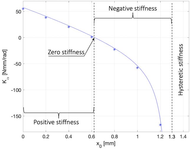
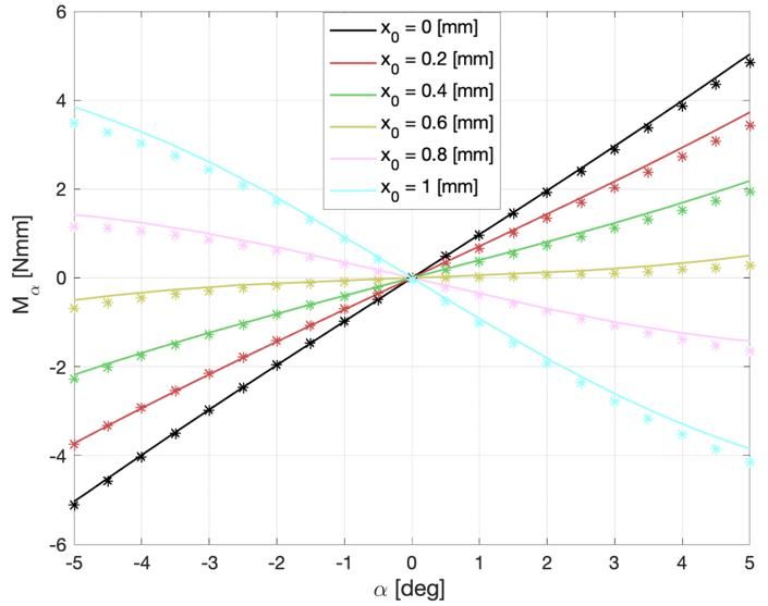
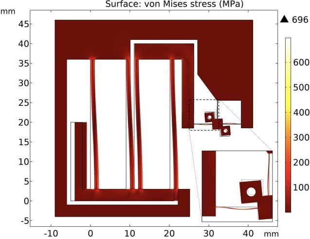
Using Eqs. (4), (12) and (13), we can obtain the pivot angle : 3. FEM results

 To validate our designed load cell, a finite element method

 − ( )2 (FEM) static study was carried out using Comsol Multiphysics 5.4
 √ 0 0 2 (14)
 =± considering geometric nonlinearities (for analyzing prestressed
 2 ( )
 structures). A first study was conducted to validate that the
 material sustains the internal stress when the load cell structure
Hence, from Eqs. (11) and (14), the applied moment can finally is maximally deformed ( = 5 deg and 0 = 1 mm). Figure 4
be calculated as: shows that the maximum von Mises stress in the structure is 696
 = (15) MPa which is below the material yield stress stated in Table 1.
2.3. Proposed dimensions
 Using the analytical model in the previous section, a flexure-
based mesoscale embodiment of the TIVOT (see Fig. 3 and Table
1) was designed to demonstrate that the stiffness tuning works
as expected, to provide numerical results for comparison to the
theoretical model and discuss possible manufacturing limits.

 Figure 4. FEM simulation of the load cell structure.

 Figure 5 illustrates the simulated pivot stiffness-preload graph
 for small pivot angles ( ≅ 0). The simulation results of the pivot
 moment-angle relation for different preloading displacements
 are shown in Fig. 6. From Eqs. (11), (14) and (15) of Sec. 2.2,
 analytical curves are traced out in Figs. 5 and 6 as the parameter
 ranges from 0 (no preload) to 2 (Euler’s critical load of a
 clamped-clamped beam [9]), with the design parameters stated
Figure 3. Mesoscale load cell prototype (illustrated as-fabricated). Two
 in Table 1 and the approximation ≅ . We avoid ≥ 2
holes are drilled in order to mount a probe on the flexure pivot.
 because the horizontal beams start to buckle even if the pivot
 To make the mechanism structurally monolithic, the linear angle is maintained to zero. This elastic instability leads to
 hysteresis in the moment-angle curve and the stress in the
stages and the linear spring are replaced by two identical parallel
 structure rises sharply due to the large beam deformations.
spring stages. The stiffness of each parallel spring stage is given
 Table 2 indicates the theoretical force sensitivity, resolution
by 0 = 2 0 ℎ30 / 30 [5].
 and range of the load cell that should be obtained on a test
 Table 1. Design parameters of the load cell. bench containing a probe needle mounted on the load cell with
 Parameter Value a length (distance from pivot center of rotation to probe tip) of
 Material (Ti-Al6-V4) 114 GPa 25 mm and a laser proximity sensor with a resolution of 10 nm
 830 MPa (for the conversion of the load cell deflection into an electrical
 signal) measuring the displacement at the probe tip. The force
 Flexure pivot ℎ 80 µm
 2 mm range is considered here to be the maximum theoretical
 4.5 mm measured force when the pivot angle stroke is mechanically
 1.4 mm stopped at 5 deg.
 5 deg
 Table 2. Theoretical force sensitivity, resolution and range of the load
 Preload mechanism ℎ0 1.05 mm
 cell for: 1) non-preloaded pivot and 2) near-zero positive stiffness pivot.
 0 2 mm Pivot stiffness 0 Sensitivity Resolution Range
 0 33 mm tuning [mm] [m/N] [µN] [mN]
 0 14.7 N/mm 1) Non-preloaded 0 0.01 1 200
 0, 1 mm 2) Near-zero 0.6 0.2 0.05 20
 positive stiffness

 The material of the load cell structure is chosen to be titanium 4. Discussion
(Ti-Al6-V4), well suited for its high yield strength on Young’s
modulus ratio ( / ). The structure is designed to be 4.1. Stiffness tuning
manufactured with wire-cut electrical discharge machining It is observed that the FEM predicts similar results as
(EDM) process, allowing cutting blades with thicknesses down to compared with the analytical model. In Fig. 5, both simulation
50 µm and machining tolerances of a few µm. In terms of load and theoretical results show that the preload allows to tune the
cell requirements, we aim for a maximum pivot stiffness (when load cell stiffness. Three stiffness regions stand out: positive
non-preloaded) lower than 60 Nmm/rad. stiffness; negative stiffness; and hysteretic stiffness.
Positive stiffness corresponds to the primary use of the load environment, the force sensitivity can fluctuate due to
cell for force sensing applications. As shown in Table 2, the force temperature variations. Instead of EDM fabricated metal
resolution can be adjusted from 1 µN down to 50 nN. If well- structure, we could use materials with low thermal sensitivity
tuned the resolution could decrease even more. However, the such as glass (using femtolaser 3D printing technology) or
lower the resolution, the lower the measuring range. Hence, we oxidized silicon (using deep reactive ion etching process).
should adjust the preloading according to the range of forces we
need to measure. We can add that load cell stiffnesses could be
higher than the non-preloaded pivot stiffness if the preload
mechanism applies a tensile preload (instead of a compressive
preload) to the pivot. Even if it is not presented in the results,
the analytical model in Sec. 2.2 can consider tensile preloads if
the parameter (defined in Eq. (4)) is a complex number.
 Negative stiffness is reached when exceeding the zero stiffness
pivot preload (see Fig. 5). This bistable behavior could open a
broader range of applications, such as, but not limited to, force
threshold sensors, force limiting devices, non-volatile bistable
mechanical memories or constant-force mechanisms if
combined with a preloaded positive-stiffness mechanism in
parallel.
 We call the region hysteretic stiffness when the preloading
displacement is higher than 1.3 mm, because there exist
multiple pivot stiffness solutions for the same pivot angle.
Indeed, the moment-angle characteristics of the pivot depends
 Figure 6. Moment-angle characteristics of the TIVOT for different
on the current buckling direction of the horizontal beams. This preload displacements. Theoretical results are represented by solid lines
hysteresis aspects of the TIVOT could be further investigated in and the FEM numerical results are represented by stars.
future studies using the analytical model presented in this
paper. 5. Conclusion

 A novel flexure-based load cell with tunable stiffness is
 presented in this paper. Analytical modeling is conducted based
 on Euler-Bernoulli beam theory and verified by carrying out FEM
 simulations. Based on these models, a monolithic mesoscale
 load cell is designed. The results show that the load cell force
 resolution can be adjusted from 1 µN down to 50 nN with a
 measuring force range of 200 mN and 20 mN respectively.
 Interestingly, the mechanism becomes bistable for certain
 adjustments, leading to a broader range of applications (force
 limiting devices, force threshold sensors, etc.).
 Future work includes a verification of the analytical and
 numerical solutions by experimental results from a load cell
 prototype fabricated in titanium using wire-cut EDM process.

 References
Figure 5. Angular stiffness versus axial preload of the TIVOT for small
 [1] Bolopion A and Régnier S, 2013, A review of haptic feedback
pivot angles ( ≅ 0). Theoretical results are represented by a solid line
 teleoperation systems for micromanipulation and microassembly,
and the FEM numerical results are represented by stars.
 IEEE Transactions on Automation Science and Engineering, 10(3),
 496–502
4.2. Load cell nonlinearities [2] Ma Z and Seiler D G (Eds.), 2016, Metrology and Diagnostic
 In Fig. 6, both simulation and theoretical results show Techniques for Nanoelectronics, 1317-39
nonlinearity. We can also notice that the numerical moment- [3] Xu Q, 2018, Micromachines for Biological Micromanipulation,
angle characteristics is asymmetrical with respect to the angle Springer International Publishing, 1-13
direction compared to the theoretical curve. The discrepancy [4] Rabenorosoa K, Clévy C and Lutz P, 2010, Active force control for
between the analytical and FEM results is considered to be robotic micro-assembly: Application to guiding tasks, 2010 IEEE
primarily due to the neglection of the pivot vertical International Conference on Robotics and Automation, Anchorage,
 AK, 2137-42
displacement in the analytical model. The stiffness
 [5] Cosandier F, Henein S, Richard M and Rubbert L, 2017, The Art of
nonlinearities of the TIVOT could be compensated using a Flexure Mechanism Design, EPFL Press, Lausanne
dedicated circuit hardware to linearize the electrical output of [6] Kim D H, Kim B and Park J O, 2004, Implementation of a
the displacement sensor or using linearization algorithms in a Piezoresistive MEMS Cantilever for Nanoscale Force Measurement
controller/processor embedded or not in the force sensor. in Micro/Nano Robotic Applications, KSME International Journal,
 18(5), 789–797
4.3. Manufacturing limits [7] De Laat M L C, Pérez Garza H H, Herder J L and Ghatkesar M K, 2016,
 Gravity can affect the measured force if the center of mass of A review on in situ stiffness adjustment methods in MEMS, Journal
 of Micromechanics and Microengineering, 26(6)
the probe is not coincident with the center of rotation of the
 [8] Vangbo M, 1998, An analytical analysis of a compressed bistable
pivot. To precisely compensate the imbalance of the probe, we buckled beam, Sensors and Actuators, A 69, 212-216
can use e.g., an adjustable constant torque mechanism mounted [9] Chajes A, 1974, Principles of Structural Stability Theory, Prentice-
in parallel on the load cell pivot. Depending on the load cell Hall, Englewood Cliffs, NJ, 8-10
You can also read