Enabling Stable Interphases via In Situ Two-Step Synthetic Bilayer Polymer Electrolyte for Solid-State Lithium Metal Batteries
←
→
Page content transcription
If your browser does not render page correctly, please read the page content below
inorganics
Article
Enabling Stable Interphases via In Situ Two-Step Synthetic
Bilayer Polymer Electrolyte for Solid-State Lithium
Metal Batteries
Ying Liu, Fang Fu, Chen Sun, Aotian Zhang, Hong Teng, Liqun Sun * and Haiming Xie *

                                          National & Local United Engineering Laboratory for Power Battery, Department of Chemistry,
                                          Northeast Normal University, Changchun 130024, China; liuy693@nenu.edu.cn (Y.L.); fuf558@nenu.edu.cn (F.F.);
                                          sunc243@nenu.edu.cn (C.S.); zhangat266@nenu.edu.cn (A.Z.); tengh466@nenu.edu.cn (H.T.)
                                          * Correspondence: sunlq446@nenu.edu.cn (L.S.); xiehm136@nenu.edu.cn (H.X.)

                                          Abstract: Poly(ethylene oxide) (PEO)-based electrolyte is considered to be one of the most promising
                                          polymer electrolytes for lithium metal batteries. However, a narrow electrochemical stability window
                                          and poor compatibility at electrode-electrolyte interfaces restrict the applications of PEO-based
                                          electrolyte. An in situ synthetic double-layer polymer electrolyte (DLPE) with polyacrylonitrile (PAN)
                                          layer and PEO layer was designed to achieve a stable interface and application in high-energy-density
                                          batteries. In this special design, the hydroxy group of PEO-SPE can form an O-H— N hydrogen
                                          bond with the cyano group in PAN-SPE, which connects the two layers of DLPE at a microscopic
                                          chemical level. A special Li+ conducting mechanism in DLPE provides a uniform Li+ flux and fast
                                          Li+ conduction, which achieves a stable electrolyte/electrode interface.LiFePO4 /DLPE/Li battery
                                          shows superior cycling stability, and the coulombic efficiency remains 99.5% at 0.2 C. Meanwhile,

                                   LiNi0.6 Co0.2 Mn0.2 O2 /DLPE/Li battery shows high specific discharge capacity of 176.0 mAh g−1 at
Citation: Liu, Y.; Fu, F.; Sun, C.;
                                          0.1 C between 2.8 V to 4.3 V, and the coulombic efficiency remains 95% after 100 cycles. This in situ
Zhang, A.; Teng, H.; Sun, L.; Xie, H.     synthetic strategy represents a big step forward in addressing the interface issues and boosting the
Enabling Stable Interphases via In        development of high-energy-density lithium-metal batteries.
Situ Two-Step Synthetic Bilayer
Polymer Electrolyte for Solid-State       Keywords: solid-state lithium metal battery; solid polymer electrolyte; double-layer electrolyte;
Lithium Metal Batteries. Inorganics       interfacial stability
2022, 10, 42. https://doi.org/
10.3390/inorganics10040042

Academic Editors: Christian Julien
and Alain Mauger
                                          1. Introduction
                                               There has been a global effort to develop next-generation energy storage systems to
Received: 28 February 2022
                                          meet the demanding requirements of electric vehicles and grid-scale energy storage [1,2].
Accepted: 21 March 2022
                                          Lithium-ion batteries (LIBs) play an indispensable role in energy storage systems due to
Published: 29 March 2022
                                          their mature technology, low cost, and high coulombic efficiency [3,4]. However, state-
Publisher’s Note: MDPI stays neutral      of-the-art LIBs with a graphite anode have almost reached the theoretical energy density
with regard to jurisdictional claims in   of 350–400 Wh kg−1 , which cannot match the increasing demand of advanced electronic
published maps and institutional affil-   devices [5,6]. To obtain high energy density batteries, using Li metal anodes (LMBs) is
iations.                                  a promising approach, owing to their high theoretical capacity (3860 mAh g−1 ) and low
                                          electrochemical potential (−3.04 V vs. standard hydrogen electrodes) [7,8]. Nevertheless,
                                          most LMBs using flammable organic liquid electrolytes have the serious issues of short
                                          circuit and leakage, which may cause a fire hazard that can lead to an explosion [9,10]. This
Copyright: © 2022 by the authors.
                                          is due to the side reaction of Li metal and electrolytes, which creates an instability interface
Licensee MDPI, Basel, Switzerland.
This article is an open access article
                                          between the anode and the electrolyte that generates lithium dendrites and produces by-
distributed under the terms and
                                          product gas that leads to battery swelling and deformation [11,12]. Compared with liquid
conditions of the Creative Commons
                                          electrolytes, solid polymer electrolytes (SPE), with high thermal and chemical stability and
Attribution (CC BY) license (https://     high Young’s modulus, that can resist the growth of lithium dendrites may be a good choice
creativecommons.org/licenses/by/          to address these safety issues [13,14].
4.0/).

Inorganics 2022, 10, 42. https://doi.org/10.3390/inorganics10040042                                       https://www.mdpi.com/journal/inorganics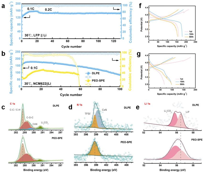
Inorganics 2022, 10, 42                                                                                           2 of 12

                                 Among the prevalent SPE, the poly(ethylene oxide) (PEO)-based electrolyte is the
                          most extensively studied electrolyte [15]. This may be attributed to the excellent flexibility
                          and good membrane-forming merits of PEO [16,17]. Owing to the anodic stability, PEO is
                          often used in lithium metal batteries, such as the matrix of single ion conduction or buffer
                          layers [18,19]. However, the electrochemical stability window of PEO is fairly narrow, as
                          it is easily oxidized to ethers at voltages above 3.9 V [20]. Moreover, recent studies have
                          shown that the cathode can accelerate the oxidation of PEO under the high voltage of
                          4.2 V [21]. These shortcomings limit the matching of PEO-based electrolytes with high
                          voltage transition metal cathodes and hinder the development of high-energy-density
                          batteries. To tackle these problems, many efforts have been made to design novel solid-
                          state electrolytes (SSEs) and to form stable electrolyte-electrode interfaces [22,23]. A novel
                          idea is to construct a multilayered solid electrolyte [24,25]. The multilayered structure is
                          compatible with high voltage cathodes and is stable when used with lithium metal anodes,
                          making it suitable for use with high-voltage lithium metal batteries [26]. However, as the
                          number of electrolyte layers increases, new interfaces are introduced, and the impedance
                          of the battery will increase accordingly [27].
                                 In this paper, we propose a double-layer polymer electrolyte (DLPE) produced by
                          an in situ two-step synthetic method. The first step involves the formation of polyacry-
                          lonitrile (PAN)-SPE on the cathode and the second involves the cross-linking of PEO-SPE
                          on PAN-SPE. This in situ synthetic method contributes to creating an intimate contact
                          at the electrode-electrolyte and electrolyte-electrolyte interfaces. More importantly, once
                          PEO contacts with PAN, the hydroxy group of PEO-SPE can form an O-H— N hydrogen
                          bond with the cyano group in PAN-SPE, which connects the two layers of DLPE at a
                          microscopic chemical level [28]. As a result of the synergistic effect of the physical and
                          chemical connections, the interfacial impedance of the battery is almost invariable after
                          cycling. Li+ transport at the PEO-SPE and PAN-SPE interfaces is achieved through the
                          synergistic effect of cyano repulsion and ether attraction. This special Li+ conducting
                          mechanism in DLPE provides uniform Li+ flux and fast Li+ conduction, which results in
                          stable electrolyte/electrode interfaces. The coulombic efficiency of a LiFePO4 /DLPE/Li
                          battery was shown to be 99.5% after 130 cycles, showing superior cycling stability. With
                          the DLPE incorporated in a LiNi0.6 Co0.2 Mn0.2 O2 battery, a capacity of 176.0 mAh g−1 was
                          achieved between 2.8 V to 4.3 V, with the coulombic efficiency remaining around 95% after
                          100 cycles.

                          2. Results and Discussion
                          2.1. Li Ion Transportation Mechanism in DLPE
                               To construct an SSE that would be compatible with both the Li anode and the high
                          voltage cathode, double-layer polymer electrolytes were designed and combined into a
                          whole. The DLPE consisted of two layers, a PEO-based solid polymer electrolyte (PEO-
                          SPE) and a PAN-based solid polymer electrolyte (PAN-SPE). As shown in Figure 1a, the
                          PAN-SPE precursor was scraped on a prepared cathode and dried in a vacuum oven.
                          Then, the PEO-SPE precursor was covered on the PAN-SPE, dried in the vacuum oven
                          and photocured under an ultraviolet (UV) lamp. This in situ manufacture method can
                          minimize the interfacial impedance between membranes and contribute to faster Li ion
                          transport at the electrolyte-electrolyte interface (Figure S1). More intriguingly, once PEO
                          contacts with PAN, the hydroxy group of PEO-SPE can form an O-H— N hydrogen bond
                          with the cyano group in PAN-SPE (Figure 1b), which connects the two layers of DLPE at
                          a chemical microscopic level. Both the physical and chemical connections contribute to
                          faster Li ion transport at the electrolyte/electrolyte interface. In addition, the solvents in
                          the electrolyte manufacturing process are different. It was found that PEO was soluble in
                          acetonitrile and PAN was soluble in N,N-dimethyl formamide (DMF), but PAN was almost
                          insoluble in acetonitrile (Figure S2). Given this, PAN aggregated on one side, and PEO
                          entirely aggregated on the other side, ensuring good interfacial contact, while avoiding
                          interpenetration between the two layers. The interfacial resistance of the PAN-SPE battery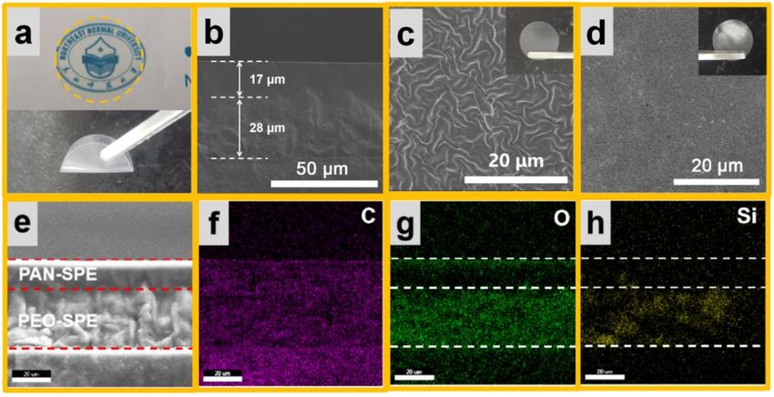
acetonitrile and PAN was soluble in N,N-dimethyl formamide (DMF), but PAN was al-
                          most insoluble in acetonitrile (Figure S2). Given this, PAN aggregated on one side, and
Inorganics 2022, 10, 42   PEO entirely aggregated on the other side, ensuring good interfacial contact, 3while        of 12 avoid-
                          ing interpenetration between the two layers. The interfacial resistance of the PAN-SPE
                          battery was large, but the introduction of PEO-SPE increased compatibility with the elec-
                          trode (Figure
                          was large, but S3).  As a result of the
                                          the introduction           in situincreased
                                                                PEO-SPE       synthesis  method, thewith
                                                                                      compatibility     interfacial  resistance of
                                                                                                            the electrode
                          (Figure
                          the DLPES3).battery
                                       As a result
                                               was of  the in situ
                                                     smaller  thansynthesis    method,
                                                                     that of the        the interfacial
                                                                                  PAN-SPE               resistance
                                                                                              and PEO-SPE           of thetogether
                                                                                                                stacked
                          DLPE battery was smaller
                          (PAN-SPE/PEO-SPE)           than that(Figure
                                                    batteries    of the PAN-SPE   andimpedance
                                                                         1c,d). The    PEO-SPE stacked    together (PAN-
                                                                                                   of PAN-SPE/PEO-SPE          bat-
                          SPE/PEO-SPE)    batteries (Figure 1c,d). The  impedance  of PAN-SPE/PEO-SPE
                          tery cycles increased greatly from 1 to 50 cycles, which delivered poor           batterycycle
                                                                                                                    cyclesstability.
                          increased greatly from 1 to 50 cycles, which delivered poor cycle stability. However, the
                          However, the impedance of DLPE was almost stable after 10 cycles because of the close
                          impedance of DLPE was almost stable after 10 cycles because of the close interfacial contact.
                          interfacial contact.

                          Figure 1. (a) Schematic illustration of DLPE membrane preparation, (b) structure diagram of DLPE;
                          Figure 1. (a) Schematic illustration of DLPE membrane preparation, (b) structure diagram of
                          Nyquist plots of the interfacial resistance after 50 cycles for (c) DLPE battery and (d) PAN-SPE/PEO-
                          DLPE; Nyquist plots of the interfacial       resistance after 50 cycles for (c) DLPE battery and (d) PAN-
                          SPE battery, (e) the mechanism of Li+ conduction in DLPE.
                          SPE/PEO-SPE battery, (e) the mechanism of Li+ conduction in DLPE.
                               Figure 1e demonstrates the Li ion transport between the two-layer electrolyte and the
                                Figure 1e demonstrates
                          electrolyte-electrolyte interface. the  Li ion transport
                                                             In PEO-SPE,            between the
                                                                            PEO is cross-linked     two-layer
                                                                                                 with          electrolyte
                                                                                                      Tetraethylene  glycol and the
                          electrolyte-electrolyte
                          dimethyl ether (TEGDME)     interface.
                                                        to form aInthree-dimensional
                                                                     PEO-SPE, PEO network
                                                                                        is cross-linked  with
                                                                                                 structure,    Tetraethylene
                                                                                                            which  disrupts    gly-
                          the structure  of PEO,   expands    the region  of the  amorphous    phase,  and  accelerates
                          col dimethyl ether (TEGDME) to form a three-dimensional network structure, which dis-         the
                          extent the
                          rupts  of PEO   chain segment
                                      structure   of -PEO,motion.
                                                            expands Thethe
                                                                         ether groupofofthe
                                                                            region       TEGDME     can notphase,
                                                                                             amorphous      only dissociate
                                                                                                                   and accelerates
                          LiTFSI into Li and TFSI , but also has a weak interaction with Li , which facilitates fast Li+
                                         +                                                      +
                          the extent of PEO chain segment motion. The ether group of TEGDME can not only dis-
                          transportation in PEO-SPE.     Compared     with the transport mechanism of PEO, in+ PAN-SPE,
                          sociate LiTFSI into Li and TFSI , but also has a weak interaction with Li , which facilitates
                                                   +            -
fast Li+ transportation in PEO-SPE. Compared with the transport mechanism of PEO
PAN-SPE, the functional cyano group of PAN becomes an electron-withdrawing gro
Inorganics 2022, 10, 42 due to the conjugation effect, which not only repels Li+, but also fixes TFSI -. During
4 of 12
movement of the PAN segments, most of the anions are bounded by -C≡N, and Li+ is c
tinuously pushed by -C≡N under the action of the electric field, which regulates
transport
the andcyano
functional facilitates
group uniform Li deposition
of PAN becomes [29]. However, high
an electron-withdrawing group crystallinity
due to the limits
+ -
transport ofeffect,
conjugation longwhich
PAN notchains,
only and
repelsthe
Li introduction
, but also fixesof TEGDME
TFSI . Duringsolves this problem [
the movement
of the PAN segments, most of the anions are bounded by -C ≡ N, and Li + is continuously
TEGDME is uniformly distributed between the PAN chains, which reduces the interm
pushed -C≡Nand + transport and
lecular byforces under the action
provides of the
more electric
free volumefield,for
which
the regulates
chains toLiconduct Li+ dissociat
facilitates uniform Li deposition [29]. However, high crystallinity+limits the transport of
resulting in a higher Li transport rate. At the interface, Li transport at the PEO-SPE
+
long PAN chains, and the introduction of TEGDME solves this problem [30]. TEGDME is
PAN-SPEdistributed
uniformly interfacesbetween
is achieved through
the PAN chains,thewhich
synergistic
reduceseffect of cyano repulsion
the intermolecular forces and et
attraction. +
and provides more free volume for the chains to conduct Li dissociation, resulting in a
higher Li+ transport rate. At the interface, Li+ transport at the PEO-SPE and PAN-SPE
interfaces is achievedof
2.2. Characteristics through
DLPEthe synergistic effect of cyano repulsion and ether attraction.
Scanning electron
2.2. Characteristics of DLPEmicroscope (SEM) and energy dispersive spectroscopy (EDS) m
pings were used
Scanning to confirm
electron microscope the(SEM)
double-layer
and energystructure.
dispersive As presented(EDS)
spectroscopy in the
map-cross-sect
(Figure
pings 2b),
were thetothicknesses
used of PEO-SPEstructure.
confirm the double-layer and PAN-SPE were in
As presented 28the
and 17 μm, respectiv
cross-section
The total
(Figure 2b),thickness of theofDLPE
the thicknesses PEO-SPE wasand
around 45 μm—relatively
PAN-SPE were 28 and 17 µm, thinrespectively.
among double-la
The total thickness
electrolytes of thebeen
that have DLPEreported.
was around 45 EDS
The mappingsthin
µm—relatively among2e–h,
(Figure double-layer
Figure S4) clea
electrolytes that have been reported. The EDS mappings (Figures
illustrate the double-layer structure of the electrolyte and the homogeneous 2e–h and S4) clearly
material
illustrate the double-layer structure of the electrolyte and the homogeneous material dis-
tribution in each layer. Furthermore, the electrolyte exhibits a Janus structure, which
tribution in each layer. Furthermore, the electrolyte exhibits a Janus structure, which has
excellentflexibility.
excellent flexibility. (Figure
(Figure 2a).side
2a). One One sideDLPE
of the of the
wasDLPE wasand
irregular, irregular,
the other and the other s
side was
was smooth.
smooth. The difference
The difference in thedepended
in the surface surface depended on the
on the physical physical of
characteristic characteristic
PEO and of P
and PAN.
PAN. The SEMTheofSEMPEO-SPEof PEO-SPE
showed ashowed
wrinkled a wrinkled texture
texture (Figure 2c), (Figure
which is 2c), which is the t
the typical
structure of cross-linked
ical structure polymers.polymers.
of cross-linked These wrinkles
Thesewere evenly distributed
wrinkles were evenly throughout the throu
distributed
PEO-SPE, causing the surface to be not smooth. In contrast, there was
out the PEO-SPE, causing the surface to be not smooth. In contrast, there was a smoa smooth and flat
surface without any crystallized phase in the SEM image of PAN-SPE (Figure 2d), which
and flat surface without any crystallized phase in the SEM image of PAN-SPE (Figure
demonstrated that the structure was extremely dense.
which demonstrated that the structure was extremely dense.
.
Figure 2. (a) Optical photograph of DLPE membrane. (b) SEM image of the cross-section of DLPE
Figure 2. (a)
membrane. Optical
SEM imagesphotograph of of
of the surface DLPE membrane.
(c) PEO-SPE (b)PAN-SPE
and (d) SEM image of the cross-section
membranes. (e–h) EDS of DL
membrane.
mappings SEM
of the images ofofthe
cross-section surface
DLPE of (c) PEO-SPE and (d) PAN-SPE membranes. (e–h) EDS
membrane.
mappings of the cross-section of DLPE membrane.
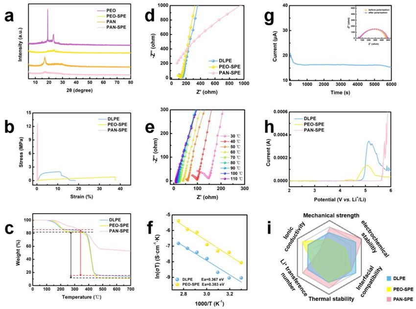
The results of X-ray diffraction (XRD) show the crystallinity changes of the SPEs
(Figure 3a). Compared with pure PEO, the diffraction peaks of PEO-SPE from 19◦ to 24◦
The results of X-ray diffraction (XRD) show the crystallinity changes of the SPEs (F
were weakened and broadened. This is because the addition of TEGDME caused cross-
ure 3a).with
linking Compared withincrease
PEO, which pure PEO, the diffraction
the amorphous peaks
region. of PEO-SPE
Simultaneously, SiOfrom 19° to 24° w
2 further
weakened and broadened. This is because the addition of TEGDME caused
disturbed the ordered structure and reduced the high crystallinity of PEO to some extent. cross-link
with PEO,
However, thewhich increase
diffraction peak the amorphous
of SiO region.
2 was relatively Simultaneously,
weak, SiO2 further
indicating the number of SiO2 distur
molecules exposed to the surface of electrolyte were very few. In addition,
the ordered structure and reduced the high crystallinity of PEO to some extent. the sharp Howe
the diffraction peak of SiO2 was relatively weak, indicating the number of SiO2 molecu
exposed to the surface of electrolyte were very few. In addition, the sharp peak of p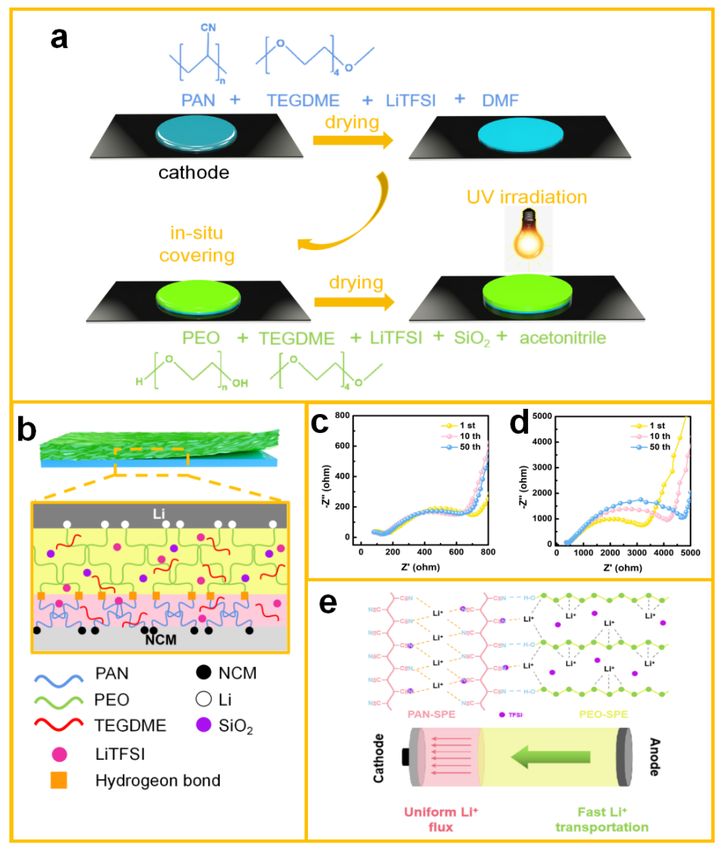
Inorganics 2022, 10, 42                                                                                               5 of 12

                          peak of pure PAN in 17◦ disappeared, replaced by the smooth peak of PAN-SPE. This
                          was due to the introduction of TEGDME. As a plasticizer, TEGDME occupies space in
                          PAN long chains, which gives PAN chains larger free volume in which to maneuver.
                          Naturally, the increase in the amorphous region increased the ionic conductivity and
                          benefitted the electrochemical properties of PAN-SPE, matching closely the results for the
                          ionic conductivity. In consequence, the ionic conductivity of PAN solid electrolyte increased
                          from 2.5 × 10⁻¹⁷ S cm−1 to 2 × 10⁻⁶ S cm−1 (Figure S5). Tensile strength measurements
                          were carried out to test the mechanical properties of PEO-SPE, PAN-SPE and DLPE. As
                          illustrated in Figure 3b, the maximal tensile strength and strain of PEO-SPE were 0.8 MPa
                          and 38%, respectively. The corresponding characteristics of PAN-SPE were 12.7 MPa and
                          3.8%, respectively. High tensile strength can slow down the kinetics of deposition and
                          inhibit dendrite propagation, and high tensile strain is beneficial to the assembly of batteries.
                          Nevertheless, neither PEO-SPE nor PAN-SPE were perfect. The DLPE neutralized their
                          shortcomings, with maximal tensile strength and strain of 1.96 MPa and 10%, respectively.
                          The structure of DLPE was mechanically strong enough to reduce the formation of the
                          dendrite nuclei and to facilitate the process of batteries assembly. Thermo-gravimetric
                          analysis (TGA) was used to study the thermal decomposition and stability of electrolytes.
                          The TGA curves of DLPE were stable until 125 ◦ C (Figure 3c), which indicated that all
                          the electrolytes could meet most of the working temperature requirements of lithium-ion
                          batteries. The weight loss at 125 ◦ C of PAN-SPE was due to the evaporation of TEGDME.
                          The weight loss at 125 ◦ C of DLPE and PEO-SPE was due to the degradation of TEGDME
                          and PEO which were not cross-linked (Figure S6). The weight loss at 350 ◦ C was mainly
                          due to the decomposition of the cross-linked PEO-SPE. However, DLPE evidenced a 14%
                          weight loss at 350 ◦ C, which was less than PEO-SPE. This was because PAN-SPE has high
                          thermal stability, with 55 % weight retention observed at 700 ◦ C. In consequence, the
                          introduction of PAN-SPE improved the thermal stability of DLPE compared to that that
                          of PEO-SPE.

                          Figure 3. (a) XRD patterns of pure PEO, PEO-SPE membrane, pure PAN and PAN-SPE membranes.
                          (b) Stress-strain curves of DLPE, PEO-SPE and PAN-SPE membranes. (c) TGA curves of DLPE,
                          PEO-SPE and PAN-SPE membranes. (d) EIS curves of DLPE, PEO-SPE and PAN-SPE membranes.
                          (e) EIS analysis and (f) Arrhenius linear fitting plots of the DLPE at various temperatures. (g) AC
                          curve and impedance spectra before and after polarization. (h) linear sweep voltammetry (LSV)
                          curves of DLPE, PEO-SPE and PAN-SPE. (i) Radar plots that compare the performance of DLPE,
                          PEO-SPE and PAN-SPE.
Inorganics 2022, 10, 42 6 of 12
Ionic conductivity is one of the important indexes by which to measure SSEs. Although
PAN possesses numerous excellent physical characteristics, a pure PAN electrolyte cannot
charge and discharge normally. Despite addition of plasticizer, the ionic conductivity of
PAN-SPE was still not high enough, resulting in low battery capacity. For this reason,
PEO-SPE with an ionic conductivity of 9.5 × 10⁻⁵ S cm−1 was used to combine with
PAN-SPE with a conductivity of 2 × 10⁻⁶ S cm−1 . As a result, the obtained DLPE had an
ionic conductivity of 3.8 × 10⁻⁵ S cm−1 at ambient temperature (Figure 3d). Although
use of DLPE requires some concessions with respect to ionic conductivity, it improved
other electrochemical and physical properties. In addition, the ionic conductivity of DLPE
at different temperatures demonstrated that the electrolyte can бoperate normally in a
range of 30–110 ◦ C, which is consistent with the results of TGA (Figure 3e). Generally, the
migration process of Li+ in SSB can be divided into two steps: the dissociation of lithium
salts and the diffusion of Li+ in electrolytes [31,32]. Due to the high dielectric constant of
TEGDME, which can achieve effective separation of anion-cation pairs in electrolytes, the
dissociation of lithium salts is not key to the migration of Li+ . The migration of Li+ along
polymer chains is the rate-determining step, which needs to overcome energy barriers. The
activation energy (Ea) of DLPE and PEO-SPE for ion transfer can be calculated by the slope
of the line in Figure 3f and the Arrhenius equation. The Arrhenius equation,
Ea
σT = Aexp −
KB T
where σ is the ionic conductivity, T is the absolute temperature, KB is the Boltzmann
constant, A is the pre-exponential constant, and the Ea is the activation energy. The Ea
values upon Li+ transfer in electrolytes were calculated to be 0.367 eV and 0.383 eV for DLPE
and PEO-SPE, respectively. DLPE had a lower migration barrier for ion transport than
PEO-SPE, owing to the unique Li+ transport pathway in PAN-SPE. It is well-known that
the cyano group is a strong electron-sucking group that can immobilize anions effectively.
Li+ could transfer uniformly in PAN-SPE without considering the influence of TFSI- , which
caused the high Li+ transference number of 0.64 for PAN-SPE (Figure S7a). However,
PEO-SPE had a low Li+ transference number (~0.20) (Figure S7b). So, as the middle
ground, the Li+ transference number of DLPE was ~0.41 (Figure 3g). The linear sweep
voltammetry (LSV) curves of DLPE, PEO-SPE and PAN-SPE were measured to test the
electrochemical stability window. To match the NCM cathode materials, the operating
voltage range of lithium-ion batteries is 3–4.5 V (vs. Li/Li+ ). This requires that the solid
polymer electrolytes can ensure normal and stable operation of the batteries within the
electrochemical stability window. In Figure 3h, for the PAN-SPE, the LSV curve remained
stable until 5.6 V; so PAN-SPE would not decompose under 5.6 V. However, the LSV
curve of PEO-SPE showed fluctuation at 4.2 V, which can be interpreted in terms of the
decomposition of PEO-SPE during the oxidation process. To achieve a balance, a wide
electrochemical stability window of 0–4.8 V can be derived from the LSV curve of DLPE,
which indicates that the heterogeneous double-layer design can play a vital role in high
voltage electrolytes. In summary, the DLPE possesses high ionic conductivity, high Li+
transference number, wide electrochemical stability window, good mechanical strength
and thermal stability, superior in comparison with PEO-SPE and PAN-SPE (Figure 3i).
2.3. Interfacial Compatibility of DLPE and Li Anode
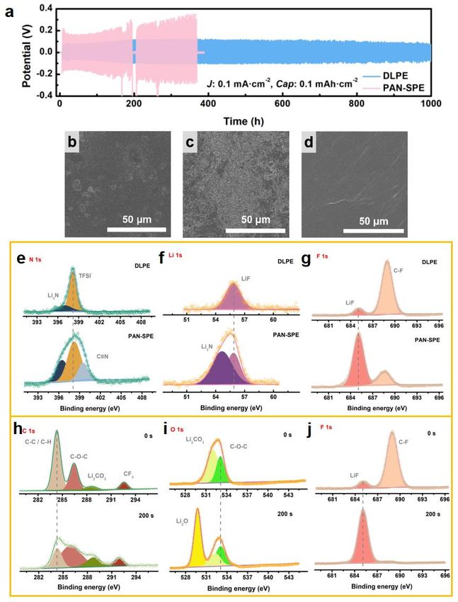
The long-term electrochemical compatibility and stability with Li metal were measured
by galvanostatic charge/discharge voltage profiles in symmetric Li batteries. The DLPE
was sandwiched between two 0.6 mm Li foils. As shown in Figure 4a, from the very
beginning, PAN-SPE had a polarization voltage of 0.13 V, and a short circuit after 195 h.
Although the battery was recharged and discharged 12 h later, the polarization voltage
increased, finally reaching 0.36 V and plummeting after 370 h, resulting in a short circuit.
The voltage profile suggests that PAN-SPE reacted with Li metal continuously, which
caused the huge polarization voltage, while the battery short circuit occurred finally as22, 10, x FOR PEER REVIEW 7 of 12
increased,
Inorganics 2022, 10, 42 finally reaching 0.36 V and plummeting after 370 h, resulting in a short circuit. 7 of 12
The voltage profile suggests that PAN-SPE reacted with Li metal continuously, which
caused the huge polarization voltage, while the battery short circuit occurred finally as
the side reactionthecontinued.
side reactionIncontinued.
contrast, after the voltage
In contrast, was
after the stable,
voltage wasthestable,
DLPE theexhibited
DLPE exhibited
a relatively flatapolarization
relatively flat voltage
polarization voltage
profile, withprofile, with
slightly slightly decreased
decreased polarization
polarization voltagevoltage
from 95 mV (200 h) to 85 mV (900 h). The results show that covering PEO-SPE, which which
from 95 mV (200 h) to 85 mV (900 h). The results show that covering PEO-SPE, has has a
low polarization voltage (Figure S8), on the side of PAN-SPE, could effectively reduce the
a low polarization voltage (Figure S8), on the side of PAN-SPE, could effectively reduce
side reactions.
the side reactions.
Figure 4. Voltage profiles of (a) Li/PAN-SPE/Li and Li/DLPE/Li symmetric batteries at a current
Figure 4. Voltage profiles of (a) Li/PAN-SPE/Li and Li/DLPE/Li symmetric batteries at a current
density of 0.1 mA cm−2 . The corresponding SEM images at Li metal anode surface after 50 cycles
density of 0.1 mA cm−2. The corresponding SEM images at Li metal anode surface after 50 cycles
(b) for DLPE; (c) for PAN-SPE. (d) SEM image of the surface of pure Li foil. (e–g) High-resolution
(b) for DLPE; (c) for PAN-SPE. (d) SEM image of the surface of pure Li foil. (e–g) High-resolution
XPS spectra of DLPE and PAN-SPE anode after 50 cycles. (h–j) High-resolution XPS spectra of DLPE
XPS spectra of DLPE and PAN-SPE anode after 50 cycles. (h–j) High-resolution XPS spectra of
anode after 50 cycles before and after sputtering for 200 s.
DLPE anode after 50 cycles before and after sputtering for 200 s.Inorganics 2022, 10, 42 8 of 12
To observe the surface morphology of the Li metal anode, the DLPE battery and
the PAN-SPE battery with 100 cycles were disassembled. As shown in Figure 4b, after
100 cycles, the Li anode of the DLPE battery achieved smooth deposition with metal luster,
benefitting from the uniform Li+ flux of PAN-SPE. In contrast, the surface of the Li metal
anode from the PAN-SPE battery showed a lot of “dead lithium” and large voids caused
by the “passivation effect” (Figure 4c), which is the reaction of the cyano group in PAN
and the Li metal anode. As a strong polar group, the cyano group, with no constraint,
can react with the active Li metal, forming a passivation layer on the surface of the Li
anode. This passivation layer has a huge impedance and thickens as the charging and
discharging occurs, which hinders the transport of Li+ . The passivation effect attenuates
the capacity of batteries. Exposing the PEO-SPE side of the DLPE to the Li anode solved
this problem perfectly.
In addition, compared with the surface of pure Li (Figure 4d), there was a passivation
layer on the surface of the DLPE anode, which had a thin solid electrolyte interphase (SEI)
layer. The characteristics of the formed SEI layer are known to be related to its chemical
composition, which was further analyzed by X-ray photoelectron spectroscopy (XPS).
PEO-SPE contacts with the anode, which can form stable SEI on the anode (Figure S9),
so we chose PAN-SPE as the comparison sample. Figure 4e–g shows the high-resolution
XPS spectra of the DLPE battery and the PAN-SPE battery after 100 cycles, which are
the spectra for N 1s, Li 1s and F 1s, respectively. As shown in the spectra, the SEI of the
DLPE battery mostly consisted of Li3 N and LiF. Li3 N and LiF are known as superior Li+
conductors and can provide fast Li+ transport and uniform Li+ flux [33,34]. In the N 1s
XPS spectra of PAN-SPE (Figure 4e), the peak, located at ~399.5 eV, was attributed to the
-C≡N on the surface of the Li anode. The cyano group of PAN obtained electrons during
the charge-discharge process, and reacted with the Li anode, resulting in an increase in
battery internal resistance and capacity loss. To prevent direct contact between PAN and Li,
the design of the double-layer DLPE has advantages. Due to the existence of ethers, the SEI
layer has a dual-layer structure [35]. As shown in the C 1s XPS spectrum (Figure 4h), the
intensify of C-C (~284.6 eV, C 1s), as the skeleton of the polymers, declined after sputtering,
indicating the polymer content in the outer layer of SEI was higher than that of the inner
layer. A new Li2 O peak at 531.0 eV in the O 1s spectrum appeared, which originated from
the reaction between the -C-O-C- group in the polymer and the Li metal. It was determined
that the inner layer of SEI was inorganic oxide Li2 O, and the outer layer of SEI was organic
polymer with C-O-C. In addition, as shown in the F 1s spectra (Figure 4j), the content of
LiF sharply increased, indicating that the composition of SEI had a large number of LiF
molecules apart from Li2 O. The hard inner layer of SEI had high mechanical strength, which
could effectively inhibit the formation of lithium dendrite crystal nuclei and make lithium
deposition more uniform, while the soft SEI outer layer could adapt to the deformation of
the lithium metal anode during the Li ion stripping/depositing process. As a result, LMBs
with DLPE showed a stable SEI and had excellent electrochemical performance.
2.4. Interfacial Compatibility of DLPE and Cathode
The batteries were assembled to evaluate their electrochemical performance. To
demonstrate the practicality of DLPE in Li metal batteries, an LiFePO4 (LFP)/DLPE/Li
battery was assembled and tested. Figure 5a shows the cycle performance of DLPE batteries
at a rate of 0.2 C at 30 ◦ C. The specific discharge capacity of DLPE battery after activation
at 0.2 C was 148.1 mAh g−1 , with 98.8% retention after 130 cycles. The coulombic efficiency
remained above 99.5% from beginning to end, verifying excellent electrochemical stability.
In addition, the LiNi0.6 Co0.2 Mn0.2 O2 (NCM622)/DLPE/Li and NCM622/PEO-SPE/Li
batteries were assembled to test their electrochemical performance under high voltage. As
shown in Figure 5b, the specific discharge capacity of the DLPE battery at 0.1 C between
2.8 V to 4.3 V was 176.0 mAh g−1 , and the coulombic efficiency remained around 95%
after 100 cycles. Conversely, batteries with PEO-SPE could not maintain stable charge
and discharge and their coulombic efficiency attenuated rapidly after 50 cycles. This was22, 10, x FOR PEER REVIEW 9 of 12
Inorganics 2022, 10, 42 9 of 12
100 cycles. Conversely, batteries with PEO-SPE could not maintain stable charge and dis-
charge and their coulombic efficiency attenuated rapidly after 50 cycles. This was ascribed
to the fact that ascribed to the fact
the PEO-based that electrolyte
solid the PEO-basedwassolid electrolyte
intolerant to was
highintolerant
voltage to high
and hadvoltage
a and
had a low Li+ transference number. These features caused great damage at the electrode-
low Li transference number. These features caused great damage at the electrode-electro-
+
electrolyte interfaces. The side reaction led to the decomposition of the electrolyte and
lyte interfaces. The side reaction led to the decomposition of the electrolyte and the intense
the intense accumulation of the electric double layer [36]. The introduction of PAN-SPE
accumulation ofimmobilized
the electric anions
doubleoflayer [36]. The introduction of PAN-SPE immobilized
lithium salts, reducing the concentration gradient and forming a
anions of lithium salts, reducing the concentration
stable cathode electrolyte interphase (CEI) gradient
[37]. and forming a stable cathode
electrolyte interphase (CEI) [37].
.
Figure 5. (a) Electrochemical
Figure 5. (a) Electrochemical performance ofperformance of LFP//Li
LFP//Li using DLPE. using DLPE. (b) Electrochemical
(b) Electrochemical perfor- performance
of NCM622//Li
mance of NCM622//Li using DLPE using
andDLPE and PEO-SPE.
PEO-SPE. (c–e) High-resolution
(c–e) High-resolution XPSXPS spectra
spectra of of DLPEand
DLPE and PEO-SPE
PEO-SPE cathode after 50 cycles. Charge-discharge curves of NCM622//Li with different cyclesassembled by
cathode after 50 cycles. Charge-discharge curves of NCM622//Li with different cycles
assembled by (f) (f) DLPE
DLPE andand(g)
(g)PEO-SPE
PEO-SPE at
at 0.1
0.1 C.
C.
XPS was carried out to explore the composition of CEI. It has been mentioned that
XPS was carried out to explore the composition of CEI. It has been mentioned that
PEO could be oxidized when contacting the transition metal oxide cathode, and would
PEO could be oxidized
produce aswhen contacting
a by-product, the ,transition
Li2 CO metal oxide cathode, and would
3 increasing the thickness of the CEI during charging and
produce as a by-product,
dischargingLiand
2CO 3, increasing
accelerating the
the thickness
decline of thecapacity.
in battery CEI during charging
As shown and 5e, the
in Figure
discharging andconstituents
accelerating the on
of CEI decline in battery
the surface capacity.
of PEO-SPE As shown
battery after 100 incycles
Figure 5e, Li
were the
2 CO3 and
constituents of LiF.
CEIInoncontrast,
the surface of PEO-SPE
LiF made battery
up the majority after 100ofcycles
constituent the CEI were LiDLPE
of the 2CO3 andbattery after
LiF. In contrast,sputtering
LiF made(Figure
up theS10), whichconstituent
majority was beneficial to the
of the CEIrapid transfer
of the Li+ andafter
DLPEofbattery forming of a
stable
sputtering (Figure CEIwhich
S10), [38]. This
waswas attributed
beneficial to to
thethe preferential
rapid transferinteraction
of Li+ andofforming
the cyanoofgroup
a and
NCM622 cathode, which was confirmed by the appearance of
stable CEI [38]. This was attributed to the preferential interaction of the cyano group and-C ≡ N in Figure 5c (~286.7 eV,
C 1s) and Figure 5d (~399.5 eV, N 1s). The CEI with abundant LiF could provide efficient
NCM622 cathode,+ which was confirmed by the appearance of -C≡N in Figure 5c (~286.7
Li diffusion channels, leading to a lower polarization of the DLPE batteries than that of
eV, C 1s) and Figure 5d (~399.5
the PEO-SPE eV, (Figure
batteries N 1s). The5f,g).CEI
Thewith abundant
internal LiF
resistance of could
the DLPE provide effi-
batteries increased
cient Li+ diffusion channels, leading to a lower polarization of the DLPE batteries
slightly after 50 cycles because the PAN-SPE blocked direct contact between PEO and the than
that of the PEO-SPE batteries (Figure 5f,g). The internal resistance of the DLPE batteries
increased slightly after 50 cycles because the PAN-SPE blocked direct contact between
PEO and the cathode and the EO segments could not be decomposed which controlled
the thickening of CEI.Inorganics 2022, 10, 42 10 of 12
cathode and the EO segments could not be decomposed which controlled the thickening
of CEI.
3. Conclusions
In this study, we designed a DLPE with PEO-SPE contacting the anode and PAN-SPE
contacting the cathode for high-performance Li metal batteries. DLPE exhibited a wide
electrochemical stability window (0–4.8 V) and an excellent Li+ transference number (~0.4).
An LFP/DLPE/Li battery exhibited superb cycle performance, with coulombic efficiency
remaining above 99.5% after 130 cycles at 30 ◦ C. Moreover, the specific discharge capacity
of an NCM622/DLPE/Li battery was 176.0 mAh g−1 at 4.3 V, and the coulombic efficiency
remained around 95 % after 100 cycles. This design of double-layer electrolytes offers an
ideal strategy to solve the interfacial problem of high-energy-density Li metal batteries.
Supplementary Materials: The following are available online at https://www.mdpi.com/article/
10.3390/inorganics10040042/s1, Figure S1: Optic photos of DLPE by in situ two-step method;
Figure S2: Photos of PAN dissolution in ACN and DMF; Figure S3: The Nyquist plot of NCM622/DLPE/Li,
NCM622/PEO-SPE/Li and NCM622/PAN-SPE/; Figure S4: LiThe EDS mapping of N element for the
DLPE membrane; Figure S5: (a) The Nyquist plot of PAN and PAN-SPE, (b) the initial of the Nyquist
plot; Figure S6: TGA curves of pure PEO; Figure S7: AC curve and impedance spectra before and
after polarization of (a) PAN-SPE and (b) PEO-SPE; Figure S8: Voltage profiles of the Li/PEO-SPE/Li
symmetric batteries at a current density of 0.1 mA cm−2 ; Figure S9: (a–c) High-resolution XPS spectra
of DLPE and PEO-SPE anode after 50 cycles; Figure S10: High-resolution XPS spectra of (a) PEO-SPE
and (b) DLPE cathode after 50 cycles before and after sputtering for 200 s.
Author Contributions: Conceptualization, H.X. and L.S.; methodology, Y.L.; software, F.F.; validation,
A.Z., H.T. and F.F.; formal analysis, C.S.; investigation, Y.L.; resources, H.X.; data curation, Y.L.;
writing—original draft preparation, Y.L.; writing—review and editing, F.F. and L.S.; visualization,
L.S. All authors have read and agreed to the published version of the manuscript.
Funding: This research received no external funding.
Institutional Review Board Statement: Not applicable.
Informed Consent Statement: Not applicable.
Data Availability Statement: The data presented in this study are available on request from the
corresponding author.
Acknowledgments: This research was supported by the R&D Program of Power Batteries with Low
Temperature and High Energy, Science and Technology Bureau of Changchun (19SS013); Key Subject
Construction of Physical Chemistry of Northeast Normal University; National Natural Science
Foundation of China (22102020); the Fundamental Research Funds for the Central Universities
(2412020FZ007, 2412020FZ008).
Conflicts of Interest: The authors declare no conflict of interest.
References
1. Fan, L.; Wei, S.; Li, S.; Li, Q.; Lu, Y. Recent Progress of the Solid-State Electrolytes for High-Energy Metal-Based Batteries. Adv.
Energy Mater. 2018, 8, 1702657. [CrossRef]
2. Chen, Z.; Chen, W.; Wang, H.; Zhang, C.; Qi, X.; Qie, L.; Wu, F.; Wang, L.; Yu, F. Lithiophilic anchor points enabling endogenous
symbiotic Li3N interface for homogeneous and stable lithium electrodeposition. Nano Energy 2022, 93, 106836. [CrossRef]
3. Li, W.; Rao, S.; Xiao, Y.; Gao, Z.; Chen, Y.; Wang, H.; Ouyang, M. Fire boundaries of lithium-ion cell eruption gases caused by
thermal runaway. iScience 2021, 24, 102401. [CrossRef]
4. Zhang, R.; Shen, X.; Zhang, Y.T.; Zhong, X.L.; Ju, H.T.; Huang, T.X.; Chen, X.; Zhang, J.D.; Huang, J.Q. Dead lithium formation in
lithium metal batteries: A phase field model. J. Energy Chem. 2021. [CrossRef]
5. Zhang, S.; Ueno, K.; Dokko, K.; Watanabe, M. Recent Advances in Electrolytes for Lithium-Sulfur Batteries. Adv. Energy Mater.
2015, 5, 1500117. [CrossRef]
6. Zhao, T.; Li, S.; Liu, F.; Wang, Z.; Wang, H.; Liu, Y.; Tang, X.; Bai, M.; Zhang, M.; Ma, Y. Molten-Li infusion of ultra-thin
interfacial modification layer towards the highly-reversible, energy-dense metallic batteries. Energy Storage Mater. 2022, 45,
796–804. [CrossRef]Inorganics 2022, 10, 42 11 of 12
7. Ren, X.; Zou, L.; Cao, X.; Engelhard, M.H.; Liu, W.; Burton, S.D.; Lee, H.; Niu, C.; Matthews, B.E.; Zhu, Z.; et al. Enabling
High-Voltage Lithium-Metal Batteries under Practical Conditions. Joule 2019, 3, 1662–1676. [CrossRef]
8. Lee, K.; Han, S.; Lee, J.; Lee, S.; Kim, J.; Ko, Y.; Kim, S.; Yoon, K.; Song, J.H.; Noh, J.H.; et al. Multifunctional Interface for High-Rate
and Long-Durable Garnet-Type Solid Electrolyte in Lithium Metal Batteries. ACS Energy Lett. 2021, 7, 381–389. [CrossRef]
9. Ma, Z.; Chen, J.; Vatamanu, J.; Borodin, O.; Bedrov, D.; Zhou, X.; Zhang, W.; Li, W.; Xu, K.; Xing, L. Expanding the low-temperature
and high-voltage limits of aqueous lithium-ion battery. Energy Storage Mater. 2022, 45, 903–910. [CrossRef]
10. Wang, M.; Wang, J.; Si, J.; Chen, F.; Cao, K.; Chen, C. Bifunctional composite separator with redistributor and anion absorber for
dendrites-free and fast-charging lithium metal batteries. Chem. Eng. J. 2022, 430, 132971. [CrossRef]
11. Liu, F.; Xu, R.; Wu, Y.; Boyle, D.T.; Yang, A.; Xu, J.; Zhu, Y.; Ye, Y.; Yu, Z.; Zhang, Z.; et al. Dynamic spatial progression of isolated
lithium during battery operations. Nature 2021, 600, 659–663. [CrossRef]
12. Fu, F.; Lu, W.; Zheng, Y.; Chen, K.; Sun, C.; Cong, L.; Liu, Y.; Xie, H.; Sun, L. Regulating lithium deposition via bifunctional
regular-random cross-linking network solid polymer electrolyte for Li metal batteries. J. Power Sources 2021, 484, 229186.
[CrossRef]
13. Duan, H.; Fan, M.; Chen, W.P.; Li, J.Y.; Wang, P.F.; Wang, W.P.; Shi, J.L.; Yin, Y.X.; Wan, L.J.; Guo, Y.G. Extended Electrochemical
Window of Solid Electrolytes via Heterogeneous Multilayered Structure for High-Voltage Lithium Metal Batteries. Adv. Mater.
2019, 31, e1807789. [CrossRef] [PubMed]
14. Dastafkan, K.; Wang, S.; Rong, C.; Meyer, Q.; Li, Y.; Zhang, Q.; Zhao, C. Cosynergistic Molybdate Oxo-Anionic Modification of
FeNi-Based Electrocatalysts for Efficient Oxygen Evolution Reaction. Adv. Funct. Mater. 2021, 32, 2107342. [CrossRef]
15. Lu, J.; Zhou, J.; Chen, R.; Fang, F.; Nie, K.; Qi, W.; Zhang, J.N.; Yang, R.; Yu, X.; Li, H.; et al. 4.2 V poly(ethylene oxide)-based
all-solid-state lithium batteries with superior cycle and safety performance. Energy Storage Mater. 2020, 32, 191–198. [CrossRef]
16. Ma, Y.; Sun, Q.; Wang, S.; Zhou, Y.; Song, D.; Zhang, H.; Shi, X.; Zhang, L. Li salt initiated in-situ polymerized solid polymer
electrolyte: New insights via in-situ electrochemical impedance spectroscopy. Chem. Eng. J. 2022, 429, 132483. [CrossRef]
17. Chen, L.; Li, Y.; Li, S.P.; Fan, L.Z.; Nan, C.W.; Goodenough, J.B. PEO/garnet composite electrolytes for solid-state lithium batteries:
From “ceramic-in-polymer” to “polymer-in-ceramic”. Nano Energy 2018, 46, 176–184. [CrossRef]
18. Yuan, H.; Luan, J.; Yang, Z.; Zhang, J.; Wu, Y.; Lu, Z.; Liu, H. Single Lithium-Ion Conducting Solid Polymer Electrolyte with
Superior Electrochemical Stability and Interfacial Compatibility for Solid-State Lithium Metal Batteries. ACS Appl. Mater. Interfaces
2020, 12, 7249–7256. [CrossRef]
19. Yang, Z.; Yuan, H.; Zhou, C.; Wu, Y.; Tang, W.; Sang, S.; Liu, H. Facile interfacial adhesion enabled LATP-based solid-state lithium
metal battery. Chem. Eng. J. 2020, 392, 123650. [CrossRef]
20. Wan, Z.; Lei, D.; Yang, W.; Liu, C.; Shi, K.; Hao, X.; Shen, L.; Lv, W.; Li, B.; Yang, Q.H.; et al. Low Resistance-Integrated
All-Solid-State Battery Achieved by Li7La3Zr2O12 Nanowire Upgrading Polyethylene Oxide (PEO) Composite Electrolyte and
PEO Cathode Binder. Adv. Funct. Mater. 2019, 29, 1805301. [CrossRef]
21. Nie, K.; Wang, X.; Qiu, J.; Wang, Y.; Yang, Q.; Xu, J.; Yu, X.; Li, H.; Huang, X.; Chen, L. Increasing Poly(ethylene oxide) Stability to
4.5 V by Surface Coating of the Cathode. ACS Energy Lett. 2020, 5, 826–832. [CrossRef]
22. Zhang, J.; Wang, P.F.; Bai, P.; Wan, H.; Liu, S.; Hou, S.; Pu, X.; Xia, J.; Zhang, W.; Wang, Z.; et al. Interfacial Design for a 4.6 V
High-Voltage Single-Crystalline LiCoO2 Cathode. Adv. Mater. 2022, 34, e2108353. [CrossRef] [PubMed]
23. Yoon, T.; Soon, J.; Lee, T.J.; Ryu, J.H.; Oh, S.M. Dissolution of cathode-electrolyte interphase deposited on LiNi0.5Mn1.5O4 for
lithium-ion batteries. J. Power Sources 2021, 503, 230051. [CrossRef]
24. Liang, J.Y.; Zeng, X.X.; Zhang, X.D.; Zuo, T.T.; Yan, M.; Yin, Y.X.; Shi, J.L.; Wu, X.W.; Guo, Y.G.; Wan, L.J. Engineering Janus
Interfaces of Ceramic Electrolyte via Distinct Functional Polymers for Stable High-Voltage Li-Metal Batteries. J. Am. Chem. Soc.
2019, 141, 9165–9169. [CrossRef]
25. Cao, Z.; Zheng, X.; Wang, Y.; Huang, W.; Li, Y.; Huang, Y.; Zheng, H. Tailoring a multifunctional, boron and fluoride-enriched solid-
electrolyte interphase precursor towards high-rate and stable-cycling silicon anodes. Nano Energy 2022, 93, 106811. [CrossRef]
26. Ma, L.; Chen, S.; Li, N.; Liu, Z.; Tang, Z.; Zapien, J.A.; Chen, S.; Fan, J.; Zhi, C. Hydrogen-Free and Dendrite-Free All-Solid-State
Zn-Ion Batteries. Adv. Mater. 2020, 32, e1908121. [CrossRef]
27. Song, H.; Sun, Y.; Zhu, J.; Xu, J.; Zhang, C.; Liu, T. Hydrogen-bonded network enables polyelectrolyte complex hydrogels
with high stretchability, excellent fatigue resistance and self-healability for human motion detection. Compos. Part B Eng.
2021, 217, 108901. [CrossRef]
28. Wang, X.; Hao, X.; Xia, Y.; Liang, Y.; Xia, X.; Tu, J. A polyacrylonitrile (PAN)-based double-layer multifunctional gel polymer
electrolyte for lithium-sulfur batteries. J. Membr. Sci. 2019, 582, 37–47. [CrossRef]
29. Pham, M.N.; Subramani, R.; Lin, Y.H.; Lee, Y.L.; Jan, J.S.; Chiu, C.C.; Teng, H. Acylamino-functionalized crosslinker to synthesize
all-solid-state polymer electrolytes for high-stability lithium batteries. Chem. Eng. J. 2022, 430, 132948. [CrossRef]
30. Jyothi, N.K.; Venkataratnam, K.K.; Murty, P.N.; Kumar, K.V. Preparation and characterization of PAN-KI complexed gel polymer
electrolytes for solid-state battery applications. Bull. Mater. Sci. 2016, 39, 1047–1055. [CrossRef]
31. Zhang, S.J.; Yin, Z.W.; Wu, Z.Y.; Luo, D.; Hu, Y.Y.; You, J.H.; Zhang, B.; Li, K.X.; Yan, J.W.; Yang, X.R.; et al. Achievement of
high-cyclability and high-voltage Li-metal batteries by heterogeneous SEI film with internal ionic conductivity/external electronic
insulativity hybrid structure. Energy Storage Mater. 2021, 40, 337–346. [CrossRef]
32. Lu, W.; Sun, L.; Zhao, Y.; Wu, T.; Cong, L.; Liu, J.; Liu, Y.; Xie, H. Elongating the cycle life of lithium metal batteries in carbonate
electrolyte with gradient solid electrolyte interphase layer. Energy Storage Mater. 2021, 34, 241–249. [CrossRef]Inorganics 2022, 10, 42 12 of 12
33. Zhang, W.; Wu, Q.; Huang, J.; Fan, L.; Shen, Z.; He, Y.; Feng, Q.; Zhu, G.; Lu, Y. Colossal Granular Lithium Deposits Enabled
by the Grain-Coarsening Effect for High-Efficiency Lithium Metal Full Batteries. Adv. Mater. 2020, 32, e2001740. [CrossRef]
[PubMed]
34. Xu, S.M.; Duan, H.; Shi, J.L.; Zuo, T.T.; Hu, X.C.; Lang, S.Y.; Yan, M.; Liang, J.Y.; Yang, Y.G.; Kong, Q.H.; et al. In situ fluorinated
solid electrolyte interphase towards long-life lithium metal anodes. Nano Res. 2020, 13, 430–436. [CrossRef]
35. Ding, J.F.; Xu, R.; Yan, C.; Li, B.Q.; Yuan, H.; Huang, J.Q. A review on the failure and regulation of solid electrolyte interphase in
lithium batteries. J. Energy Chem. 2021, 59, 306–319. [CrossRef]
36. Wen, K.; Tan, X.; Chen, T.; Chen, S.; Zhang, S. Fast Li-ion transport and uniform Li-ion flux enabled by a double-layered polymer
electrolyte for high performance Li metal battery. Energy Storage Mater. 2020, 32, 55–64. [CrossRef]
37. Zhang, J.N.; Li, Q.; Wang, Y.; Zheng, J.; Yu, X.; Li, H. Dynamic evolution of cathode electrolyte interphase (CEI) on high voltage
LiCoO2 cathode and its interaction with Li anode. Energy Storage Mater. 2018, 14, 1–7. [CrossRef]
38. Zhao, J.; Liang, Y.; Zhang, X.; Zhang, Z.; Wang, E.; He, S.; Wang, B.; Han, Z.; Lu, J.; Amine, K.; et al. In Situ Construction of
Uniform and Robust Cathode-Electrolyte Interphase for Li-Rich Layered Oxides. Adv. Funct. Mater. 2020, 31, 2009192. [CrossRef]You can also read