EN GF500 GE1065HD Operation manual - Motor-driven - Waspper
←
→
Page content transcription
If your browser does not render page correctly, please read the page content below
Operation manual
                                                                                                              EN
                                                            GF500
                                                    GE1065HD

                                                    Motor-driven

Original Manual of Use
*The picture of the device is illustrative and it doesn`t have to comply with the actual view of the device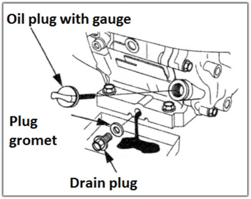
CONTENTS

Product use in compliance with its determination pg. 1
Environment protection . . . . . . . . . . . . ……………..pg. 1
Safety . . . . . . . . . . . . . . . . . . . . . . . . . …………….. pg. 1
Scope of the supply . . . . . . . . . . . . . . . . . . . . . …... pg. 2
Assembly. . . . . . . . . . . . . . . . . . . . . . . . . . . . …….. pg. 2
Entry into service . . . . . . . . . . . . . . . . . …………… pg. 3
Engine. . . . . . . . . . . . . . . . . . . . . . . . . . . . . . . …… pg. 3
Engine maintenance . . . . . . . . . . . . . . . . . . . . . . . . pg. 5
Pump . . . . . . . . . . . . . . . . . . . . . . . . . . . . ………… pg. 6
Help with failures . . . . . . . . . . . . . . . . . . . ………….pg. 11
Guarantee. . . . . . . . . . . . . . . . . . . . . . . . . . . . . . ... pg. 11
Technical data. . . . . . . . . . . . . . . . . . . . . . …………pg. 12
Declaration of compliance with EU standards . . . . pg. 12

 WARNING
Read this original manual of use and included safety instructions before the first usage of your new device. Act
accordingly. Keep the manual for a later usage or for another owner of the device.

 Product use in compliance with its determination

This high-pressure washer can be used:
 - With the sufficient amount (min. 50L) of the clean water in the tank.
- for washing of machines, vehicles, buildings, tools, facades, building exteriors, garden tools etc., along with
the high-pressure stream of water (in case of need with adding detergents);
- with accessories and spare parts approved by the company Waspper s.r.o..
- In the environment without any direct exposure to the splashing polluted water with the solid particles.
- The device has to be stored in the environment protected against the weather conditions.

 Environment protection

Package materials can be recycled. Dispose the package according to the ecological rules.
Old machines contain evaluable recycling substances, which should be reused again. The old machines have
to be disposed ecologically.
Cleaning operations, out of which waste water with oil content arise e.g. during engine cleaning or cleaning of
the machinery floor, can be executed only in the washrooms with the oil separators. You can execute the work
with detergents only on workplaces sealed to be impermeable to fluids outflow and attached to the sewer system
for the polluted water. Avoid emission of detergents to the aquatic resources or soil.

 Safety

  Safety instructions

Before you use this device for the very first time, unconditionally read included “Safety instructions for the high-
pressure washers”.
Acoustic protection devices and eye protection devices are appropriate to use during operation of the washer

for the purpose of acoustic and eye protection.

                                                                                                                       1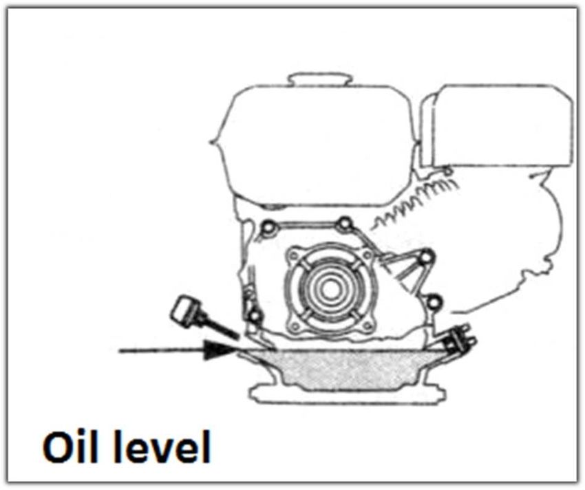
Levels of danger

     DANGER - Warning before imminent danger, which may cause serious injuries or death.

     WARNING - Warning before a possible dangerous situation, which could result in minor injuries.

    WARNING - Warning before a possible dangerous situation, which could result in material injuries.

 Safety elements

     WARNING - Safety elements serve for the user protection against injuries and they mustn`t be altered or
withdrawn from their operation. In case of damage they have to be replaced only by an original spare part.

Security covers of hot or rotating parts

Security covers serve for protection of the high-pressure washer against injuries resulting from the high
temperatures of some parts of combustion engine or against the injury caused by the rotating parts of the
device.

Security features of the combustion engine and pump

Safety switch of the low level of engine oil serves for an automatic engine shutdown in case the oil level
decreases below the minimal level. We avoid the engine damage caused by insufficient lubrication of internal
parts in this way. However, this safety element does not substitute the obligation to check oil level before usage
of the device.
Further important information is in the part – ENGINE (pg. 3).

Water level sensor in the tank serves for the secure switching off the pump in case there is not sufficient amount
of the water serving for engine cooling.
 Temperature indicator placed on to the pump serves for engine protection against the water with the
temperature higher than the maximum operating temperature of the engine.

Vacuum sensor placed near the water filter serves for engine protection when filter element of the
water filter is choked. It would cause a higher risk of cavitation and premature wear of the pump.
Important information is in the part - PUMP (pg. 6).

Scope of the supply

Content of the delivery device is portrayed on the package or in the order of goods. After unpacking check the
completeness of the content. If some parts are missing or you find damages arisen during the transport, please,
inform the seller about it.

It is required additionally

Clean water resource for the filling the
tank or direct supply of the pump by
pressurised-water with the yield of
15L/min.

Assembly
The single device is assembled in the production plant. Complete the pressure gun, extension piece and nozzle.
Attach the high-pressure gun at the ending of the high-pressure hose. In the next step it is necessary to fill up
the engine with delivered engine oil according to the instructions in the section ENGINE (pg. 3) and pour fresh
petrol with octane number 95.

                                                                                                                     2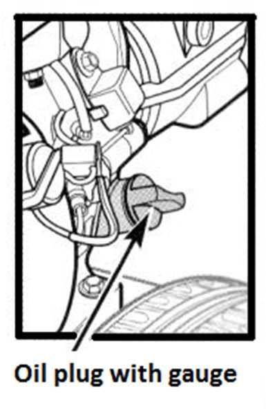
Entry into service
Supply with water
WARNING Do not start up the pump without water in the tank. The minimal amount is
around 50L. The pump switches off in case of lower water level. The water in the tank
has to be clean, without solid particles or mud. Polluted water damages internal
components of the high-pressure pump and clogs the water filter prematurely and
sucking of water from the tank becomes more difficult. It can result into the automatic
engine shutdown. Unless the pump exerts the pressure until 30 seconds after engine
start-up, switch off the engine and proceed according to the instructions in the section
Problems solution! Dry run for more than 30 seconds causes pump damage!
Damages on the equipment for the reason of failing to obey this instruction result in the termination of the
guarantee.
Engine
It is NECESSARY to pour the right amount of the supplied engine oil to the engine
before the first start-up of the pump. Packed engine oil bottle can contain bigger
amount of the filler than it is necessary for the given type of the engine. The exact
amount of the filler is laid down in the Technical specification. We advise to decrease the
outlet pressure of the water according to the instructions on the page 8 for smoother
start-up of the cold engine.
Place the pump on the horizontal surface. Open the plug of the oil sump where the oil
dipstick is located. Pour around ¾of the required amount of the oil to the engine. Screw
the plug in the engine. At the position of the switch C in the position OFF (0) (picture
at the bottom) rotate the engine by pulling the start-up lead. Open the plug, wipe the
dipstick and check the engine oil level.
CAUTION: The dipstick shows the correct oil level only after the full screwing up to
the engine cut out. Pour in the oil in the way, so the oil is in the top half between MIN and
MAX.
Open the plug of the tank and pour the petrol into the tank. The fresh petrol with octane number 91 and more is
necessary to use for the full engine power. The old petrol has different physical characteristics and can cause
the engine hunt or the decreased pumping capacity. Use only the clean petrol without oil additions - Your
engine is of four-stroke type.
DANGER
Running engine produces
the carbon monoxide, colourless and
poisonous gas without odour.
Inhalation of carbon monoxide may cause nausea, headache, dizziness, vomiting and death!
The device can be used only in the outer environment where the proper ventilation is ensured. It is also
necessary to ensure that the exhausted gases wouldn`t get to the closed rooms through unsealed
hatchways.
If you work with the running engine, turn the device in the direction so that the standing people and
hatchways of the buildings (garages, porches, cellars etc.) do not face the exhaust pipes.
The engine produces the waste heat during operation which results in the presence of many hot
components (exhaust, engine cylinder), which can cause the serious burns in case of touching. There
is a fire hazard if these hot components come into contact with flammable materials.
DANGER
Petrol vapours are extremely
flammable and explosive and in case
of the wrong manipulation they can cause burns, fire or explosion.
Let the engine cool down for 5 minutes before pouring the petrol into the tank. Then open the tank hood
and start to pour the petrol to the tank carefully. NEVER fill up the petrol to the edge because it heats
and spreads during engine usage and that can cause the petrol leakage through the plug followed by
the explosion or fire. NEVER turn over the high-pressure device to the position where the petrol could
leak from the tank.
NEVER try to start up the engine if the components of fuel supply, ignition components or security
features are damaged.
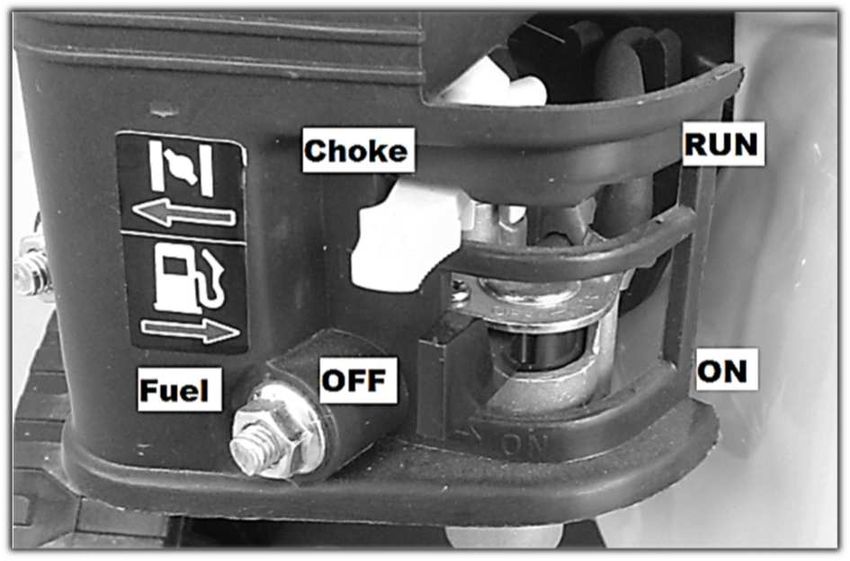
3Turn the engine switch C and fuel D to the position ON
(I).
Move the gear control lever B to the position .
Move the choke control lever A to the position CHOKE.
Hold the pump handle firmly by one hand and jump start
leads handle by another hand.
Pull jump start leads until you feel the engine resistance.
Then pull the handle sharply to avoid the back run.
If the engine does not start up for the very first time, press
the gun and release the accumulated pressure of the water
in a safe way. Then repeat starting by pulling the jump start
leads.
Start-up can be made considerably easier by pressure
decrease.
WARNING Back ran of the jump start leads
(engine action against the movement of the jump
start leads) pull your shoulder and arm towards
the engine faster than you are able to leave hold
of it. It can cause wrenches, contusions or
fractures.
After starting move the choke control lever A SLOWLY to
the position RUN.
ENGINE SWITCH OFF
Engine switching off proceeds according to the following steps
Move the engine speed control lever(page 4)B to the half, towards the position and let the engine run
on cut down revolutions for 15 - 20 seconds. After that turn the engine switch C and fuel D to the position
OFF (0).
WARNING: The engine is equipped with the engine oil level sensor which switches off the engine if the oil
level cuts down to the dangerous level. This function does not substitute the regular engine oil level check.
Failure of the control can result in unrecoverable damage on the internal engine components. Such a damage
is not covered by this guarantee. The device is also protected by vacuum sensor in the suction pipes, water
level sensor in the tank and water temperature sensor in the pump.
NEVER spray water on the hot engine. Such as action can cause ingress of water into the fuel or ignition
system. Use a wet cleaning rag to clean the engine and compressed air to exhaust the dust from the filter area.
MAINTENANCE
Every 8 hours or daily Engine oil level check
Air filter area check and check of the impurities from the exhaust.
After first 5 hours Change of engine oil
Every 50 hours or at Clean the air filter
the end of the season Change of engine oil
Every 100 hours Checking and setting up the electrode of the sparking plug.
Checking fuel lines
During operation, in certain cases, the protective covers made of tin can be released because of vibrations.
These components need to be tightened because an action of long-term vibrations on the released cover causes
the damage of fixing holes. In case the protective cover of the exhaust, air filter or cooling fan is damaged, these
parts have to be replaced by the original spare parts because only in this case the maximum operation safety
can be ensured.
4Spare parts are available through the producer or certified service point. Complete list of the components is
published in this manual or on the Internet sites of the producer.
Winter storage
Correct long-term storage is a key to attain trouble free operation in the next season.
You prolong the service life of the engine by the correct storage.
Following steps provide the maximal engine components protection against corrosion and wear of the engine
slide parts.
The engine cannot run and engine temperature has to be lower than 50°C. Clean the engine from dust and
impurities with a wet cleaning rag. Clean potential damages with paint or an oily rag after drying. In this way
you prevent the tin from interaction with the air, followed by corrosion.
Open the fuel tank plug and check the amount of the fuel in the tank. Long-term presence of the fuel in the tank
during storage has a negative impact on the fuel quality. It can result in engine hunt or decreased engine power.
Discharge the petrol from the tank and carburettor by a means of the relief valve screw placed at the bottom
part of the carburettor. DO NOT TURN ENGINE OVER.
THERE IS A DANGER OF OIL LEAKS! We advise to change the engine oil at the end of the
season. The service life of the engine will be prolonged.
Change of engine oil
We advise to change the engine oil
after use of the device (according to the
maintenance plan). Switch off the engine. Let the
device cool a little bit, so the temperature is lower than
50°C. You will avoid potential burn injuries. It is
The
appropriate for the engine to remain warm.
warm oil leaks out from the engine
more easily.
- Unscrew the OIL PLUG WITH THE DIPSTICK.
- Place the pot of the minimal volume of 1L under the
relief valve screw.
- Release the relief valve screw carefully.
- Let the oil flow out freely to the prepared pot.
- If the oil already stopped leaking, decline the engine
mildly so that the rest of the oil would leak.
-Clean the area of the relief valve screw and tighten it back to its original place.
- Used engine oil is necessary to hand in some of the collection centres for this purpose. The engine
oil is dangerous waste!
Hour meter. The device contains hour meter. The total engine hours
(time cannot be deleted), partial engine hours ( time can be deleted by
button) are recorded. Immediate engine speed, Tasks reminders.
Hold the button minimally for 2 seconds to delete the reminder on the
recording of the total engine hours. Hold the button minimally for 2
seconds to delete the reminder on the recording of the partial engine
hours.
Pushbutton switching enables to switch from engine hours to revolutions
and from the data engine hours to RPM data.
5Pour the right amount and type of the engine oil into the
engine. The oil specification is laid down below. - The
accurate amount of the filler is written in the Technical
specification.
- Place the pump on the horizontal surface. Pour around
¾of the required amount of the oil to the engine. Screw
the plug in the engine. At the position of the switch C in
the position OFF (0) (picture at the bottom) rotate the
engine by pulling the start-up lead. Open the plug, wipe
the dipstick and check the engine oil level.
CAUTION: The dipstick shows the correct oil level
only after the full screwing up to the engine cut out. Pour
in the oil in a way that the oil is in the upper part, between
marks MIN and MAX.
Engine oil specification
The engine oil is one of the key factors influencing power and service life of the
engine.
Minimal requirements for oil are: Viscosity class 5w30, 10W30 or 10W40 with the quality class at least SF and
more (SG, SH, SJ). The usage of the engine oil 10W30 in temperatures higher than 27°C can result in the
higher oil consumption. That is why it is important to pay higher attention to the oil level if the device operates
under these temperatures and oil 10W30. In such as cases we recommend to use the oil 10W40 of the quality
class SF and higher (SG, SH,SJ). The delivered engine oil exceeds the minimal requirements for the quality
highly and ensures the safe engine operation with the minimal wear of the internal parts under the tough
operating conditions.
If the engine oil is necessary to be refilled, use only the same type and brand-mark
already present in the engine. Mixing of different oil types is not recommended!
Pump
Your pump is of all-metal character and so it ensures the long service life and non-fault run. There are moving
parts with their accurate location in the pump. Because of that fact it is NECESSARY that the water coming
into the pump would be without mechanical impurities. These impurities abrade the landing areas of the pump,
by means of which clearance between the internal components increases and the outlet pressure decreases.
DANGER
The pump generates too high
pressure in the outlet and as
the result the blowing water
has devastating effects on soft objects. Aiming water jet at people or animals IS FORBIDDEN.
Failing to obey this warning can have devastating effects with the results such as permanent
blindness, cut wounds, amputations and death.
CAUTION!
The high pressure can cause damages on soft and sensitive objects. It is not recommended
to use the water jet with the high pressure to clean rubber and tyres, glass, non-cohesive
varnish, coating and timber. If too strong water flow is applied, the surface structure can alter
or change permanently. In case of doubts we advise to try application of the pressurised-water
on the sample where the potential surface disturbance will have no impact on the functionality
or appearance of the object.
If you move the nozzle farther from the cleaning object, the pressure of the falling water
decreases and the washing effect is less aggressive. On the contrary, movement closer to the
object results in higher washing effect along with more aggressive washing effect on the
object.
6Safety elements
There is a water filter in the water entry to the pump. This filter needs to
be checked and cleaned regularly. Deposited impurities cause decreased
flow and increased vacuum during suction of the pump. It causes
deactivation of the engine safety system and the engine switches off.
Change the damaged filter or its rivet for a new one immediately.
The guarantee does not apply for the mechanical damage
on the internal parts of the pump caused by polluted
water.
Vacuum switch (pic. A)
His role is a control of the vacuum
level in the sucking part of the
pump. Too high vacuum, which is
caused for example by choked
water filter, causes cavitation and
cuts down the service life of the
engine. If the vacuum is too high,
the sensor switches off the
engine.
Overpressure relief valve
A1
A
(pic. A1) for the system
protection against the pressure higher than 6 bar.
Thermoswitch (Pic. B)
Its role is to protect the pump against the overheating. The
process of the excessive heating occurs if the engine is still
running but the high-pressure gun is switched off and no water
is running from the nozzle. The pump switches automatically to
outer water circulation. The water warms up by a continuous
water cycle. The rule is applied that the less water in the tank,
the sooner it warms up. Because of this reason, only the
water of the maximal temperature of 40°C can flow into the
water supply since if the temperature reaches 50°C, this
B switch turns off the engine and keeps this state until the
pump is cooled.
Water level switch (pic. C)
The role of this switch is a control of water level in the tank. The minimal
amount is around 50L. This amount of water is necessary for the engine
cooling during the idling state. If the water level in the tank decreases below
the minimal level, this switch stops the engine and keeps this state until the
sufficient amount of the water is refilled into the tank. The same applies in
case of pressure water usage for the supply of the pump.
C
7Pump preparation for the operation
The pump is filled up with the industrial oil. Because of the oil
D temperature change and thermal expansion during the operation,
there is an AIR VALVE (pic. D).
The operation of the pump with the low oil level or without oil
causes the permanent damage on the pump and ceases the
guarantee. Fill in the oil to the half of the control sight glass. Check
E the oil level before every use.
Place the pump to the horizontal position to check the oil level
height. Otherwise the recorded level will not correspond with the
reality. The oil level has to be in the required latitude during the
operation, so that the proper lubrication of the internal components
is ensured. You can check the oil level on the control sight glass
of the pump (picture E). It must be located close to the mark in
the centre when the engine is switched off. If the oil in the
pump is necessary to be refilled, use exclusively oil of the
class: 15w40 SF-SJ. Do not exceed the maximal oil level! It
can cause the damage on the shaft seals and oil leak from the
pump.
The pump run without water or dry can cause a permanent damage on the pump and ceases the
guarantee. Check the inflow of water before every use!
Regulation of the water pressure in the outlet
This pump enables to regulate the water pressure in the outlet in the scope of 80 Bar- 220Bar. If you want to
change the pressure, turn the controller located on the pump (picture F). Rule: when viewed from the top, the
pressure increases if you turn TO THE RIGHT (direction of the watch rotation) and decreases if you turn TO
THE LEFT. The engine load and fuel consumption grows with the increased pressure. Because of this fact the
water pressure is appropriate to be modified on the base of the particular situation. If you cut down the pressure,
you will prolong the service life of the engine and pump
Maintenance of the pump
Change the oil in the pump after first 50 hours of operation and then every 200 hours of operation. Use
the oil of the class 15w40 SF-SJ to change it. Release the
F plug located on the side part of the pump and drain the oil
from the pump. Decline the pump, so the oil would leak from
the pump housing. The oil is recommended to be changed
after using, while it is warm, it leaks more easily and
impurities are dispersed in the oil. After the old oil leaks out,
screw back the relief valve screw, pour the oil through the
opening of the plug and at the same time check the level on
the control sight glass. Proceed carefully because the oil
flows slowly inside the pump and it can often overfill.
After the oil reaches the necessary level, screw the air plug
back to the cover of the pump.
8Usage of self-priming function of detergent
The pump has self-priming function by use of vacuum from the
pot. The black nozzle, determined for the purpose of detergent
usage, is needed to start this function. The pump starts to suck
the detergent itself through the opening marked by the arrow (pic.
F). Pour the necessary amount of the detergent into the storage
tank (1 pic. G). The maximal amount of the detergent is 15 litres.
The detergent is applied diluted by water in the proportion 1:12 (1
portion of the detergent and 12 portions of water). This amount
changes according to the outlet pressure and detergent´s density.
In case the detergent is not sucked, check the sieve located at the
outlet from the storage tank ( in the internal part of the brass nut
2 pic. G). Apply the detergent by pressing the pushbutton on the
gun. This configuration does not serve for creation
of active foam. It is necessary to buy a foam lance if we want
to create the active foam (category No SP000-FL002).
G
Winter storage of the pump
Storage of the pump on places where the environment temperature is under the
freezing point can result in unrecoverable damage of the internal components if the
pump is not drained properly!
Process of discharging the remaining water from the pump: Make sure that the engine switch (pg. 4 pos. C) is
in the position OFF (0).
Unscrew the nut 2 (picture G) and discharge the water from the detergent tank. Start the engine. Put the black
nozzle into the extension piece and press the pushbutton. In such a way the remaining amount of the detergent
should get out from the detergent tube. The process of the detergent discharge is visible in the transparent tube
of the pump in the form of bubbles. If the detergent flows only from time to time, the engine can be switched
off. If there is any amount of liquid in the storage tank, disconnect the connector 2 (pic. G) in winter.
Then discharge water from the main tank. There is a connector with a plug
placed at the bottom side (pic. H). Take away the plug and let the water flow
out.
H
After flowing out all water,
N unscrew the transparent
cover of the water filter at the
bottom (pic. I) and pour out
the water.
Switch the 3-way valve (pic.
N) gradually to all positions
I and let to flow out the water
from the pipes.
9Take away the hose of the pipe directed downwards ( pic. J) and decline the
hose to enable outflow of all water from the pump. Leave the hose
disconnected until the outflow process of water is finished.
J
Disconnect the high-pressure hose in the outlet (pic. K). Then hold the jump
start leads handle and pull the lead for 10 times like when starting the
engine. The water gets out from the pump through the high-pressure opening
in this way. Pick up the back part of the frame, so that water could also flow
out from the supply hose between the tank and water filter. It is not
recommended to store the pump in the room where the temperature drops
below the freezing point. Any substantial change of the external temperatures
K can cause water vapour condensation also in the space where water does not
get under normal conditions. That can result in internal corrosion and
significant reduction of the pump and engine service life.
Preparation for operation
Place the tank frame on the straight surface so that after filling any vibrations wouldn´t move it. Check if all hose
edges are tightened enough and assembled on the right place. The detergent is not necessary to be filled into
the storage tank if its usage is not required. It has no impact on the operation of the high-pressure washer. Turn
the tank cap in the direction of the arrow, marked as OPEN on the cap ( pic. L), and open it. Fill in the tank with
clean water of the required amount, maximally 1000L. You can observe filling it on the scale (pic. M). It is
necessary to aim the water stream in the direction that would not result in the damage on the switch placed in
the centre of the tube bottom. Then close the tank cap in the direction of the arrow. You will avoid contamination
of the water by impurities and water outflow during transport. Some amount of the water can flow over the
cover if the movement is stronger and the tank is full. The cover is not water resistant! If the required
transport is over big rough terrain, it is appropriate to fill the tank up to ¾ of its capacity.
N
L M
Use of 3-way valve: The tank can also be filled via connector, placed on the front side of the frame. The position
of the 3-way valve is necessary to be set up right according to the instructions on the pictogram ( pic. N). The
rule applies: The position of the valve handle marks CLOSED way. 1. The valve handle has to be turned in the
direction toward the water filter if we want to fill the tank or get away water without the pressure washer. 2. If
we want to use the pressure water without previous tank filling for the high-pressure washer supply, let´s place
the valve handle to the left. CAUTION! The sufficient amount of water has to be in the tank to set up work
position of the float (upwards). Otherwise engine protection blocks the engine. When the engine is in
the idling state, the overflown water will flow into the tank. 3. If we want to use the water from the tank for
the high-pressure washer supply, we switch the valve to the left after previous filling in water to the tank.
Cut down the outlet pressure of the water according to the instructions in the section: Regulation of the water
pressure in the outlet. The force necessary for starting cuts down by this step. Place the nozzle with the
required angle of the water jet to the ending of the metal extension piece of the high-pressure gun. Start the
engine according to the instructions in the section ENGINE. CAUTION! The engine has to be filled with the
engine oil and petrol before starting. Set up the required water pressure. If the pump was not used for a longer
period, sucking water to the pump will take up to 20 seconds.
10The engine switches off if: There is not enough oil in the engine - there is not enough water in tank - water
sucking gets more difficult because of the choked water filter - the temperature of water or valve pump head
more than 45°C.
Problems solution
Problem Cause Solution
The pump is not able to 1.The nozzle with a big hole is used 1. Change for the right dimension of the
create the necessary water 2.The water supply is blocked. nozzle
pressure, low water flow 3. Low volume of the incoming water 2. Check the uncontrolled water flow
4.Choked the sieve for incoming water 3.Use the higher water pressure or the hose
5. The high-pressure hose is choked or the with the longer diameter
water leaks 4.Clean the sieve or replace by a new one
6. Too high temperature of the input water 5. Remove the impurities, turn the hose, rinse
7.The pressure releases from the gun or replace by a new one
8.Choked nozzle
6.Provide the colder water
9.Damaged pump
7. Check the joints tightening, change the gun
8. Clean the nozzle with a steel wire and rinse
it with a stream of water
9. Contact the service point
Pump does not take the 1. Wrong nozzle is used 1.Change the high-pressure nozzle for the
detergent 2.Insufficient amount of the detergent in the low-pressure (black) one
storage tank 2.Check the amount of the detergent 3. Clean
3. The tube or sieve is choked the hose with the stream of water, change the
suction tube
The engine runs well without 1. Low engine revolutions 1. Modify the position of the speed lever,
the load but it jerks if loaded 2. Too high water pressure check the position of the locating screw of the
speed lever
2. Cut down the output pressure of the water
with the control on the pump according to the
instruction on the page 8.
The engine stopped during the 1. The engine consumed the fuel 1.Fill the tank with the fuel
operation 2. The spark plug fell out. 2. Check the spark plug connector.
3. Low oil level in the engine 3. Check the oil level in the engine
4. Low water level in the tank 4.Fill the water to the pump
5. High vacuum in the suction pipes 5. Clean the water filter
6. High water temperature in the pump 6. Fill the cold water into the tank and let the
pump cool down.
The engine cannot start or it 1. Choked air filter 1.Clean the air filter
stats but runs jerky 2.The engine is without fuel 2.Fill the tank with the fuel
3.Old fuel 3.Change the fuel for new one or fill the tank
4. The spark plug connector is not connected to with more new fuel
the plug. 4.Check spark-plug connector
5.The sparking plug does not work 5. Change the sparking plug for new one
6. Fuel contaminated with water 6.Discharge the fuel from the tank
7. Wrong proportion of fuel mixture and carburettor, and fill in new petrol
8. Points 4-6 in the previous column 7. Contact the service point
Engine has no power 1. Choked air filter 1.Clean the air filter
2. Old fuel 1.Fill the tank with the new fuel
Use only original spare parts. You will ensure non-fault conditions for the run of your device in this way.
Guarantee
The guarantee conditions are guaranteed in every country of our distribution network. Potential failures of the
appliance will be removed for free during the guarantee period if they are caused by a material or
manufacturing defect. Please, contact your seller or the nearest authorized service point with the sales slip of
the particular device if you apply the guarantee.
You find the list of the approved service points on our web site: www.waspper.com
The company Waspper s.r.o. try continuously to improve the technical characteristics and user comfort of their
products. Because of this reason the producer reserves the right to alter the construction and controls of the
device without the previous warning of the final customer. The location of all controls and security elements
11illustrated in this manual is accurate and realistic. Any design change of the controls does not need to be
recorded in this manual.
Technical data
Device type GE1065HD GE1065BD GE1065LD GF500
Engine type Honda Briggs/Stratton Peggas G200F-L ----
GX200 196cm3/ XR950 208cm3/ series 196cm3/
4,3kw 4,7kw 4,1kw
Maximal speed 3600 rpm 3600 rpm 3600 rpm ----
Engine type Four-stroke OHV Four-stroke OHV Four-stroke OHV ----
Torque 12,4 Nm/ 2600 rpm 12,9 Nm/ 2600 rpm 12,4 Nm/ 2500 rpm ----
Sparking plug Brisk: LR15YC Brisk: DR17YC Brisk: LR14YC ----
0,7-0,8mm 0,7-0,8mm 0,7-0,8mm
Champion: RN7YC Champion: QC12YC Champion: RN7YC
NGK: BPR6ES NGK: BKR5ES NGK: BPR7ES
Tank capacity 3,1L 3,1L 3,6L 500L- water
Capacity of the oil filler 0,6L / 10w40 0,6L / 5w30 0,6L / 10w40 ----
Water pressure and flow 3200psi/ 220bar 3200psi/ 220bar 3200psi/ 220bar ----
14L/ min 14L/ min 14L/ min
Net weight 30 kg 30 kg 30 kg 105 kg
Height 64 cm 64 cm 64 cm 100 cm
Width 101 cm 101 cm 101 cm 111 cm
Length 47 cm 47 cm 47 cm 140 cm
Self-priming function of Yes Yes Yes ----
water
Fuel consumption 1,7L/ hour 1,98L/ hour 2,1L/ hour ----
Volume of detergent ---- ---- ---- 15L
bottle
Components list
Water tank
Water level indicator
Pressure gun
Hose reel drum
Engine
Tank frame
Nozzles holder and area for accumulator
Handling hole for
Forklift
12EU Declaration of Conformity
The company Waspper s.r.o. hereby declares that the water pumps defined below comply with the
relevant EU directives on occupational health and safety of the device operators. Any alteration of
the device without the prior consent from the manufacturer will render this declaration void.
Product name: High pressure washer
Type Serial number ES inspection report Noise level Guaranteed
measured noise level
GE1065HD xx0001001-xx9999999 1802/3/2019-02 97 dB 99 dB
GE1065BD
GE1065LD
GF1000 xx0001001-xx9999999 02201/3/2019-01 - -
Protokol o skúške 29032019 zo dňa 29.03.2019
Certificate issued by: TECHNICKÁ INŠPEKCIA a.s., pracovisko KOŠICE, as an accredited inspection body in
accordance with EN ISO / IEC 17020
Applicable EU Directives:
2006/42/ES (+2009/127/ES)
2004/108/ES
2000/14/ES
Standards applied:
STN EN ISO/IEC 17 020
Producer:
Waspper s.r.o, Duklianska 51, 05201 Spišská Nová Ves, Slovensko
Issued in: Spišská Nová Ves Manufacturer's representative: Marián Garbriš
Issue date: 25.9.2019 Position: Managing Director
13Warranty Certificate
Product type: Stamp and signature:
Serial number: Date of purchase:
In pursuit of service enhancement and simplification of communication with customers, the company Waspper s.r.o. recommends its
customers, who purchase this product, to register their product via the manufacturer's website: www.waspper.com. This registration
will provide inevitable data for faster processing of your complaints or consulting relevant to purchasing of spare parts and accessories.
This registration enables the customer to avoid further procedures, as submitting of the purchase receipt or the warranty certificate.
1. The manufacturer - Waspper s.r.o. - is liable for inherent defects of the product purchased, if such defects become evident within
the warranty period. Application of claims for repairs under warranty requires completion and submission of the complaint form via
the manufacturer's website: www.waspper.com. The product is covered by a full warranty of 24 months for private customers (as
defined by the Civil Code) and 12 months for corporate customers (as defined by the Commercial Code). The warranty period
commences upon completion and submission of the complaint report via the website in case of simple defects and damages. The
commencement of warranty in case of major defects starts upon the product delivery to the manufacturer's address: Waspper s.r.o,
Duklianska 51, 05201 Spišská Nová Ves. Acceptance of complaint will be notified to the customer using the contact details entered in
the complaint form.
2. The warranty does not cover defects incurred due to: wrong operation; improper handling or use contradictory to the operation
manual or instructions and recommendations from the company Waspper s.r.o; use or storage of goods within inappropriate areas,
especially with respect to temperature, dust formation or ambient humidity; exposure to direct sunlight; damage attributable to
natural disasters of force majeure. The warranty does not apply to mechanical damages, any damages due of solid particles, frost or
other weather effects. The warranty does not apply to damage to the pump caused by cavitation. Other exemptions from warranty
include damages to the engine due to lack of oil and ingress of any other but operating fluid among internal engine components.
3. Particular steps of claims processing will be notified to the customer following assessment of the scope of repair by the claims
engineer. Whenever the replacement of a damaged component can be performed by the customer, the latter will receive a relevant
spare part only. If the repair by a servicing centre is inevitable, the customer is obliged to mail the damaged device to the
manufacturer's address. The device must be complete (including accessories) and packed properly to prevent its damage during
transport, it must be free of mechanical damage and contain no operating fluids. If the goods submitted to the servicing centre shows
evident signs of damage or excessive wear, the manufacturer reserves the right to reject such consignment without acceptance.
4. Claims for repairs under warranty oblige the customer to provide the receipt of purchase (invoice, cash receipt) together with the
warranty certificate and written description in support of their claim, including photographic documentation. It is recommended to
complete the complaint form via the manufacturer's website to ensure the fastest processing of the claim as possible, if the
manufacturer acknowledges such claim as justified, the repaired item will be sent to the customer and the postage/freight will be
covered by the manufacturer.
5. If the claims engineer finds out the product does not comply qualifications for repair under warranty, the claim will be considered
unjustified and the costs of product transport to the customer will be paid by the latter.
6. Should the repair period exceed 30 days or if the product is irreparable, the customer will be offered a replacement item.
7. Justification of claims will be assessed by the claims engineer at the manufacturer. Justified claims will extend the warranty period
by the period taken by the claim processing period. Such action will be confirmed to the customer by means of a document in writing,
dispatched together with the product or sent via e-mail. If the product subject to claim contains any discontinued component, the
manufacturer will provide the customer with an adequate replacement item with its parameters corresponding with the returned
product or even better.
8. The customer undertakes to read all the information found on the packaging or in the operation manual; to do so immediately
following the product delivery, to acknowledge that preservation of the positive characteristics of the product delivered will be subject
to its proper operation and storage. Any disregard to obligations defined herein relieve the company WPW Center s.r.o. from any
liability for defects of goods or damages incurred due to breach of this obligation by the customer or any other third party. The
customer is obliged to check the intact condition of packaging and product during the purchase and takeover of the consignment from
the postman. Any damage to the packaging must be reported to the carrier and recorded immediately. Any damages found only after
unpacking of the product must be notified to the distributor within the maximum period of 4 working days. No later claims for product
damage can be accepted.
1415
You can also read