Electrically Small Wideband Monopole Antenna Partially Loaded with Low Loss Magneto-Dielectric Material
←
→
Page content transcription
If your browser does not render page correctly, please read the page content below
Article
Electrically Small Wideband Monopole Antenna Partially
Loaded with Low Loss Magneto-Dielectric Material
Aladdin Kabalan, Ala Sharaiha * and Anne-Claude Tarot

 Institut d’Electronique et des Technologies du numéRique (IETR), University of Rennes 1, 263 Avenue du Général
 Leclerc, 35700 Rennes, France; aladdin-kabalan@hotmail.com (A.K.); anne-claude.tarot@univ-rennes1.fr (A.-C.T.)
 * Correspondence: ala.sharaiha@univ-rennes1.fr

 Abstract: A miniaturized new topology of the planar monopole antenna using a Magneto-Dielectric
 Material (MDM) is proposed in this paper. The antenna element is realized by introducing slots
 partially covered by the MDM. We optimized and modified the MDM topology and dimensions to
 enhance the impact of this material on the planar monopole antenna, including slots in its structure.
 This new monopole shows a miniaturization rate of 60% of the antenna’s height (51 cm antenna’s
 height is miniaturized to 20 cm) by covering only 5% of the antenna surface by the MDM. The
 measured results show the antenna’s central working frequency of 130 MHz, while the bandwidth is
 30% using a broadband matching circuit using the Real Frequency Technique (RFT).

 Keywords: magneto-dielectric materials; planar monopole antenna; miniaturization

 1. Introduction
 Planar monopole antennas are widely used in many communication systems due to
Citation: Kabalan, A.; Sharaiha, A.; their simple structure, compact size, ease of manufacture and implementation, especially
Tarot, A.-C. Electrically Small in aeronautical applications [1–4] in the VHF and UHF frequency bands. The antenna size
Wideband Monopole Antenna is relatively important in these bands, which causes an integration problem for most of the
Partially Loaded with Low Loss applications in these bands. Therefore, a small antenna size is necessary and becomes a
Magneto-Dielectric Material.
 critical problem in communication systems.
Magnetism 2022, 2, 229–238.
 Among the various existing miniaturization techniques, the use of semi-massive
https://doi.org/10.3390/
 Magneto-Dielectric Materials (MDM) [5] is one of the most promising for reducing the
magnetism2030017
 antenna size. Instead of using a material with high permittivity, the same miniaturization
Academic Editor: Paolo Baccarelli can be obtained by using MDM of the same refractive index n = (µr ε r )0.5 with moderate
Received: 22 May 2022
 permittivity and permeability avoiding highly concentrated field confinement, and the
Accepted: 7 July 2022
 medium is far less capacitive when compared to the dielectric-only high permittivity, which
Published: 12 July 2022
 results in low antenna efficiency and narrow-band operation [6,7]. On the other hand,
 antenna matching is difficult in a medium of high permittivity because of the high-quality
Publisher’s Note: MDPI stays neutral
 factor value.
with regard to jurisdictional claims in
 Since the work of Hansen and Burke [8], magneto-dielectric materials have been
published maps and institutional affil-
 known to be more advantageous in antenna miniaturization and, in ultra-wideband antenna
iations.
 applications, since the work of Volakis [9]. Many other papers have confirmed, at least in
 theory, that magneto-dielectric materials give larger bandwidths and also better efficiencies
 compared to dielectric ones [8,10–12]. Furthermore, the MDM should have sufficiently
Copyright: © 2022 by the authors.
 low dielectric and magnetic losses tangents to ensure good performance of antennas made
Licensee MDPI, Basel, Switzerland. of them. Recent papers have proposed a new hexaferrite structure [13] with a high FOM
This article is an open access article (Figure of merit of the product µ0 , Q and the operating frequency f) which has a strong
distributed under the terms and potential for low-loss high-frequency applications.
conditions of the Creative Commons These last years, modern material manufacturing technology has made it possible to
Attribution (CC BY) license (https:// design composite or nanocomposite substrates with different kinds of magnetic inclusions
creativecommons.org/licenses/by/ mixed with dielectric host materials. Most of these MDM substrates were used to minia-
4.0/). turize planar antennas (patch, PIFA and IFA), with the ratio µr /ε r of 1.5 [12,14], 5.9 [15]

Magnetism 2022, 2, 229–238. https://doi.org/10.3390/magnetism2030017 https://www.mdpi.com/journal/magnetism
inclusions mixed with dielectric host materials. Most of these MDM substrates were used to miniaturize planar antennas (patch, PIFA and IFA), with the ratio ⁄ of 1.5 [12,14], 5.9 [15] and 2.1 [16], and loss tangents (tanδε,μ ) less than 0.1 for a frequency band up to 700 MHz. Showing a better performance compared to commercial dielectric materials. Magnetism 2022, 2 In [17], we studied the effect of MDM composed of NiZnCo ferrite, which in the VHF 230 band has a higher permeability ( = 16) than the permittivity ( = 12), on the miniatur- ization of a planar monopole antenna in the VHF band 100–200 MHz. We achieved an optimum miniaturization rate of 15%, covering only 12% of the total antenna size where and 2.1 [16], and loss tangents (tan δε,µ ) less than 0.1 for a frequency band up to 700 MHz. the intensity of the surface current is maximum. In order to increase the magnetic impact Showing a better performance compared to commercial dielectric materials. of the MDM, we propose, in this paper, modifying the monopole topology by introducing In [17], we studied the effect of MDM composed of NiZnCo ferrite, which in the slots and by optimizing the size and the position of the MDM, as well as its geometry. VHF band has a higher permeability (µr = 16) than the permittivity (ε r = 12), on the Then the effect of the air gap, due to the sheet metal thickness when using Planar MDM miniaturization of a planar monopole antenna in the VHF band 100–200 MHz. We achieved (P-MDM), on the magnetic field distribution was investigated. an optimum miniaturization rate of 15%, covering only 12% of the total antenna size where The paper is organized in the following way: after briefly presenting the fabricated the intensity of the surface current is maximum. In order to increase the magnetic impact MDM and the reference antenna in Section 2, we presented the principal results of the of the MDM, we propose, in this paper, modifying the monopole topology by introducing antenna miniaturization using a small portion of P-MDM and introduced slots in Section slots and by optimizing the size and the position of the MDM, as well as its geometry. 4. Then in Section 5, we presented a parametrical study, where the antenna geometry and Then the effect of the air gap, due to the sheet metal thickness when using Planar MDM the dimensions (P-MDM), of magnetic on the the P-MDMfieldwere optimized, distribution wasand then in Section 6, a first prototype investigated. using The P-MDM was designed and validated by measurements. paper is organized in the following way: after briefly Finally, Section presenting the7fabricated presents some concluding remarks. MDM and the reference antenna in Section 2, we presented the principal results of the antenna miniaturization using a small portion of P-MDM and introduced slots in Section 4. 2.Then MDM Description in Section 5, we presented a parametrical study, where the antenna geometry and the An MDMofwas dimensions developed the P-MDM with were the objective optimized, andof obtaining then in Sectiona high 6, a permeability first prototypewith a using low loss inwas P-MDM thedesigned frequencyandband of 100–200 validated MHz. The MDM by measurements. basedSection Finally, on a ferrite Ni-Zn-Co 7 presents some was elaborated concluding by the Lab-STICC laboratory, and the method is presented in [5]. remarks. The relative permeability (μr) and permittivity (εr) spectrum, as well as the magnetic 2. MDM and Description dielectric loss tangent in the frequency band of 100–200 MHz, are shown in Figure 1a,b, respectively. An MDM was developed with the objective of obtaining a high permeability with a lowItloss wasinobserved that between the frequency band of100 and 200 100–200 MHz.MHz,Thethe MDM ′ / ′ on ratiobased is greater than a ferrite unity Ni-Zn-Co wasvaries and elaborated by the between 1.46Lab-STICC and 1.37. laboratory, and the Magnetic losses aremethod is presented low, between in [5]. 0.03 and 0.05. This propertyTheisrelative permeability related to (µr ) dimensions the nanometric and permittivity (εr ) that of grains spectrum, as wellduring are preserved as the heat mag- netic and dielectric loss tangent in the frequency band of 100–200 MHz, are shown treatment. in Figure 1a,b, respectively. (a) (b) Figure Figure1.1.Manufactured ManufacturedMDM MDMspectrum spectrumininthe theband band1010MHz–6 MHz–6GHz. GHz.(a)(a)Typical Typicalmeasured measuredrelative relative permeability and permittivity. (b) Magnetic and dielectric loss tangents. permeability and permittivity. (b) Magnetic and dielectric loss tangents. 3. Geometry of the Planar It was observed Monopole that between 100 Antenna and 200 MHz, the ratio µ0 /ε0 is greater than unity and varies Anbetween 1.46 and (UWB) ultra-wideband 1.37. Magnetic planar losses are low, monopole between antenna 0.03 and 0.05. is designed This property to operate in the is related VHF bandto(118–156) the nanometric MHz, dimensions of grains that with the dimensions are preserved shown in Figureduring heat treatment. 2a (antenna A1); the other dimensions W2 = 5 mm and = 40° are optimized for a larger bandwidth. Figure 2b 3. Geometry shows of the the antenna Planar input Monopole impedance Antenna with a bandwidth of 31.5% (for VSWR < 2.5) around An ultra-wideband (UWB) planar monopole its resonance frequency f0 = 130 MHz. We assumed in antenna is designed our study to operate that the ground in of plane the VHF band (118–156) MHz, with the dimensions the monopole antenna has infinite dimensions. shown in Figure 2a (antenna A1); the ◦ other dimensions W2 = 5 mm and θ = 40 are optimized for a larger bandwidth. Figure 2b shows the antenna input impedance with a bandwidth of 31.5% (for VSWR < 2.5) around its resonance frequency f 0 = 130 MHz. We assumed in our study that the ground plane of the monopole antenna has infinite dimensions.
The planar monopole antenna was chosen for our project of aircraft application,
 which is the suitable type of antenna for the VHF band. The scope statement goal of re-
 ducing the antenna height from 51 cm to 20 cm corresponds to a miniaturization rate of
 60.7%. The monopole antenna with 20 cm of height called “ARef” is shown in Figure 2a,
 and its input impedance is represented on the Smith chart in Figure 2b. The size of the
Magnetism 2022, 2 antenna A1 is in the order of ⁄4.5 at the frequency 130 MHz, while the reference antenna231
 Aref must be miniaturized up to ⁄11.5.

 (a) (b)
 Figure
 Figure2. 2.(a)(a)
 Simple monopole
 Simple antenna
 monopole A1A1
 antenna ofof
 the height
 the heightofof
 510 mm,
 510 mm,and the
 and thereference
 referencemonopole
 monopole
 antenna ARef of the height of 200 mm. (b) Smith chart of the antenna’s impedances in the band 118
 antenna ARef of the height of 200 mm. (b) Smith chart of the antenna’s impedances in the band 118 to
 to 156 MHz.
 156 MHz.

 4. Miniaturization of the Monopole
 The planar monopole Antenna
 antenna was chosenUsing a P-MDM
 for our project of aircraft application, which
 In this
 is the section,
 suitable typewe of study
 antenna thefor
 effect
 the of
 VHFtheband.
 PlanarThe MDM (P-MDM)
 scope statement to shift
 goal the resonance
 of reducing the
 frequency of the reference
 antenna height from 51 cm antenna
 to 20 cmARefcorresponds
 , consideringtofor the moment thatrate
 a miniaturization the of
 metal thick-
 60.7%. The
 ness
 monopole antenna with
 of the antenna is zero.
 20 cm of height called “ARef ” is shown in Figure 2a, and its input
 We showed
 impedance in previouson
 is represented workthe [17]
 Smiththat it is in
 chart sufficient to cover
 Figure 2b. the regions
 The size close to A1
 of the antenna theis
 source
 in thewhere
 order the intensity
 of λ/4.5 at theoffrequency
 the magnetic 130field
 MHz, is while
 the highest to obtain
 the reference an optimum
 antenna Aref mustmin-be
 iaturization
 miniaturized rate.
 upTherefore,
 to λ/11.5.by covering the reference antenna partially with the P-MDM
 (3 mm thick, 60 mm height) on both sides (see Figure 3a), antenna A2 is obtained. The
 4. Miniaturization
 latter resonates at 176ofMHz the Monopole
 lowering the Antenna
 frequency Using bya only
 P-MDM about 35%. We should em-
 phasize Inthat
 thisour
 section, we study
 objective was tothe effect130
 attain of MHz
 the Planar
 without MDM (P-MDM)
 increasing the to shift
 size the an-
 of the reso-
 nanceThe
 tenna. frequency
 P-MDMofthickness
 the reference antenna
 is limited to A 3 Ref
 mm , considering
 because of for the moment
 technical reasons,thatknowing
 the metal
 thickness
 that the material antenna t ahas
 of the thickness is zero.
 a direct effect on the effective medium (effective permea-
 We showed in previous
 bility and permittivity). In our application,work [17] that the itincrease
 is sufficient
 in theto cover the
 P-MDM regionsleads
 thickness closetoto
 the source where the intensity of the magnetic field is the highest
 an effective permeability more important. However, the objective is to have the desired to obtain an optimum
 miniaturization
 miniaturization rate.of Therefore,
 effect the P-MDMby covering
 with the minimumthe reference
 quantity antenna partially with the
 of the material.
 P-MDM
 In order(3 mm thick, 60high
 to achieve mm height) on both sides
 miniaturization rates,(see
 weFigure 3a), antenna
 increased the impact A2 isofobtained.
 the P-
 The latter resonates at 176 MHz lowering the frequency
 MDM. For this, we proposed the antenna A3 structure with the inclusion of two open- by only about 35%. We should
 emphasize that our objective was to attain 130 MHz without
 ended slots in this area (see Figure 3b). These two slots, with a length of 50 mm and increasing the size of the
 a
 antenna. The P-MDM thickness is limited to 3 mm because of
 thickness of 5 mm, serve to concentrate the surface currents in the area of intersection technical reasons, knowing
 that thethem
 between material thickness
 (Figure has a direct
 3c), which effect on leads
 consequently the effective mediumin
 to an increase (effective permeability
 the magnetic field
 and permittivity). In our application, the increase in the P-MDM
 intensity in the zone covered by the P-MDM. Thus, an increase in the effective permeabil- thickness leads to an
 ityeffective permeability
 of the medium more providing
 is obtained, important.a higher
 However, the objectiverate.
 miniaturization is to have the desired
 miniaturization effect of the P-MDM with the minimum
 The effective medium can be calculated numerically by simulation, quantity of the material.
 by determining
 In order to achieve high miniaturization rates, we increased
 the shift of the resonance frequency caused by the material, using the following the impact of the P-MDM.
 equation:
 For this, we proposed the antenna A3 structure with the inclusion of two open-ended slots
 in this area (see Figure 3b). These two slots, with a length of 50 mm and a thickness of
 5 mm, serve to concentrate the surface currents in the area of intersection between them
 (Figure 3c), which consequently leads to an increase in the magnetic field intensity in the
 zone covered by the P-MDM. Thus, an increase in the effective permeability of the medium
 is obtained, providing a higher miniaturization rate.
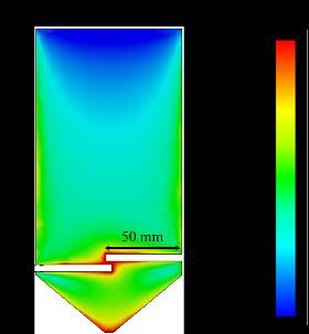
the permittivity of P-MDM does not have any effect on the resonant frequency of the an-
 tenna, and the effective permittivity is neglected.
Magnetism 2022, 2, FOR PEER REVIEW For a of about 20, the effective permeability increases from about 2.28 for the an- 4
 tenna without slots A2 to 4.6 for the antenna with the two slots A3, respectively (see Figure
 Magnetism 2022, 2 4). Consequently, the resonance frequency decreases from 175 MHz to 130 MHz, increas- 232
 ing the miniaturization rate to 60.7% (see Figure 5).
 0,
 0, = (1)
 √
 where 0, and 0, are the resonance frequencies of the antenna without and with
 MDM, respectively. are the effective permittivity and permeability, respectively.
 In the regions close to the source, the intensity of the electric field is the lowest; therefore,
 the permittivity of P-MDM does not have any effect on the resonant frequency of the an-
 tenna, and the effective permittivity is neglected.
 For a of about 20, the effective permeability increases from about 2.28 for the an-
 tenna without slots A2 to 4.6 for the antenna with the two slots A3, respectively (see Figure
 4). Consequently, the resonance frequency decreases from 175 MHz to 130 MHz, increas-
 ing the miniaturization rate to 60.7%(b)(see Figure 5).
 (a) (c)
 Figure
 Figure 3. 3. Monopole
 Monopole antenna
 antenna miniaturized
 miniaturized byby
 thethe
 P−P−MDM:
 MDM: (a)(a)without
 withoutslots
 slots(A2)
 (A2)and
 and(b)(b) with
 with two
 two
 slots of 50 mm × 5 mm (A3). (c) Density of the surface currents (A/m), which corresponds to the
 slots of 50 × 5 mm (A3). (c) Density of the surface currents (A/m), which corresponds to the intensity
 intensity of the magnetic field.
 of the magnetic field.

 The effective medium can be calculated numerically by simulation, by determining
 the shift of the resonance frequency caused by the material, using the following equation:

 f 0,air
 f 0,MDM = √ (1)
 ε e f f µe f f

 where f 0,air and f 0,MDM are the resonance frequencies of the antenna without and with
 MDM, respectively. ε e f f µe f f are the effective permittivity and permeability, respectively. In
 the regions close to the source, the intensity of the electric field is the lowest; therefore, the
 (a) permittivity of P-MDM does not(b) have any effect on the resonant frequency (c) of the antenna,
 and the effective permittivity is neglected.
 Figure 3. For
 Monopole
 a µr ofantenna
 about 20,miniaturized
 the effectiveby permeability
 the P−MDM: (a) withoutfrom
 increases slotsabout
 (A2) and
 2.28(b)
 forwith
 the two
 of 50 mm
 slotsantenna × 5 mm (A3). (c) Density of the surface currents (A/m), which corresponds
 without slots A2 to 4.6 for the antenna with the two slots A3, respectively (see to the
 intensity of
 Figure the
 Figure4). magnetic
 4. Effective field.
 Consequently,
 mediumthe resonance
 in function frequency
 of the decreases from
 relative permeability 175miniaturized
 for both MHz to 130antennas:
 MHz,
 increasing the (A2)
 without slots miniaturization
 and with tworate
 slotsto 60.7% (see Figure 5).
 (A3).

 Figure
 Figure 4. Effective
 4. Effective medium
 medium inin functionofofthe
 function the relative
 relative permeability
 permeabilityfor both
 for miniaturized
 both antennas:
 miniaturized antennas:
 without
 without slotsslots
 (A2)(A2)
 andand with
 with twoslots
 two slots(A3).
 (A3).

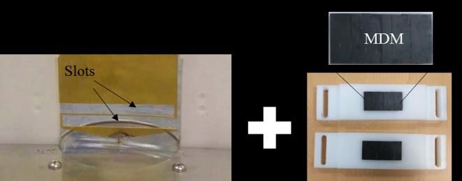
Magnetism 2022, 2, FOR PEER REVIEW
 Magnetism 2022, 2 233

 Figure 5. Imaginary parts of the input impedance of 3 antennas: ARef, A2 and A3.

 5. Parametrical Study

 Figure
 In this section, we studied the impact of the size of the P-MDM used (WMD
 5.Imaginary
 Figure 5. Imaginary parts
 parts ofinput
 of the the input impedance
 impedance of 3 antennas:
 of 3 antennas: AA3.
 ARef , A2 and Ref, A2 and A3.
 HMDM ) as well as the slot length Lslot and height Hslot on the resonance frequency
 5. Parametrical Study
 the
 5. corresponding
 Parametrical Studyμeff (see Figure 6).
 In this section, we studied the impact of the size of the P-MDM used (WMDM and
 The initial parameters are the following: WMDM = 96 mm, hMDM = 20 mm, Ls
 HMDM In) as
 this section,
 well welength
 as the slot studied the height
 Lslot and impact ofonthe
 Hslot thesize of thefrequency
 resonance P-MDMf 0 used
 and (WMD
 mm, H slot = 5 mm.
 Hthe corresponding µeff (see
 MDM ) as well as the
 Figure
 slot 6). Lslot and height Hslot on the resonance frequency
 length
 the corresponding μeff (see Figure 6).
 The initial parameters are the following: WMDM = 96 mm, hMDM = 20 mm, Lsl
 mm, Hslot = 5 mm.

 Figure 6. Parametrical study of the Antenna A3 with the parameters: H
 MDM MDM slot , W slot,L and H .
 Figure 6. Parametrical study of the Antenna A3 with the parameters: HMDM , WMDM , Lslot an
 The initial parameters are the following: WMDM = 96 mm, hMDM = 20 mm, Lslot = 50 mm,
 5.1.
 HslotOptimization
 = 5 mm. of the Position and the Dimensions of the P-MDM

 Figure
 Here, we considered H
 5.1. Optimization of the Position
 6. Parametrical study ofand
 MDM
 the
 as the height of the P-MDM. Several values of the
 theAntenna
 Dimensions
 A3ofwith
 the P-MDM
 the parameters: HMDM , WMDM , Lslot an
 wereHere,
 tested webetween
 considered 20 Hmm and 55 mm when the other dimensions were fixed wi
 MDM as the height of the P-MDM. Several values of the
 =H50 mm,
 5.1.MDM wereH tested
 Optimization = 5 mm
 between and
 slot of the Position 20 mmWand = 96
 andthe
 MDM 55 mmmm (Figure
 when
 Dimensions 7a).
 theofother
 the It is shown
 dimensions
 P-MDM in fixed
 were Figure 7b t
 with Lslot = rate
 reduction 50 mm,of fH0 slot
 as =a 5function
 mm and W ofMDM
 HMDM= 96decreased
 mm (Figureonly
 7a). Itby
 is shown
 aboutin2%,
 Figure 7b
 correspondi
 Here,
 that the reduction rate of f0 as aH
 we considered MDM as
 function ofthe height
 HMDM of the
 decreased P-MDM.
 only by aboutSeveral values of the
 2%, correspond-
 Δμeff of 0.35.
 were a ∆µ between
 ing totested of 0.35. 20 mm and 55 mm when the other dimensions were fixed wit
 Next,effwe varied the width WMDM from 8 mm to 96 mm with a constant height o
 = 50 mm, Hslot = 5 mm and WMDM = 96 mm (Figure 7a). It is shown in Figure 7b t
 = 20 mm (Figure 8a) and keeping L and Hslot the same. We can see in Figure
 reduction rate of f0 as a function of Hslot MDM decreased only by about 2%, correspondi
 at WMDM = 40 mm, the reduction rate of f0 is equal to 41% and converges slowly to 4
 Δμeff of 0.35.
 the maximum width WMDM = 96 mm.
 Next, we varied the width WMDM from 8 mm to 96 mm with a constant height o
 = 20 mm (Figure 8a) and keeping Lslot and Hslot the same. We can see in Figure
 at WMDM = 40 mm, the reduction rate of f0 is equal to 41% and converges slowly to 4
 the maximum width WMDM = 96 mm.
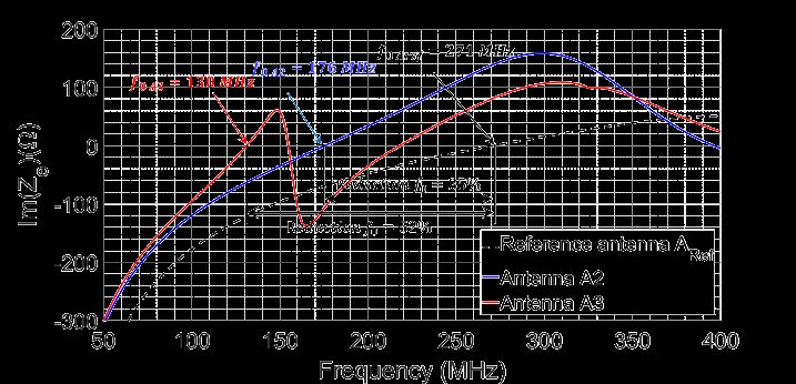
Magnetism 2022, 2, FOR PEER REVIEW 6
 Magnetism 2022, 2 234

Magnetism 2022, 2, FOR PEER REVIEW 6

 (a) (b)
 Figure 7. (a)
 Figure 7. Monopole antenna
 (a) Monopole of the height
 antenna of the200 mm with
 height 200 two
 mmslots
 withof two
 the width
 slots 50
 of mm.
 the (b) Reduc-
 width 50 mm.
 tion rate of f0 and μeff in function of P-MDM height HMDM with a constant WMDM = 96 mm.
 (b) Reduction rate of f 0 and µ eff in function of P-MDM height HMDM with a
 constant WMDM = 96 mm.

 (a) Next, we varied the width WMDM from 8 mm to(b)96 mm with a constant height of
 HMDM
 Figure 7. (a) = 20 mm (Figure
 Monopole antenna 8a) and
 of the keeping
 height Lslot
 200 mm andtwo
 with Hslot the
 slots of same. We50can
 the width mm. see(b)inReduc-
 Figure 8b
 thatofatf0W
 tion rate and
 MDMμeff= in
 40function
 mm, the ofreduction rate H
 P-MDM height f 0 is
 ofMDM equal
 with to 41%WMDM
 a constant and converges
 = 96 mm. slowly to
 49% for the maximum width WMDM = 96 mm.

 (a) (b)
 Figure 8. (a) Monopole antenna of the height 200 mm with two slots of the width 50 mm. (b) Reduc-
 tion rate of f0 and μeff in function of P-MDM width WMDM with a constant HMDM = 20 mm.

 5.2. Slots Dimensions Effect on the Miniaturization Rate
 (a)
 Here, Lslot varies between 10 mm and 90 mm (Figure (b)9a) with a constant H
 slot of 5
 mm.
 Figure The
 8. (a) P-MDM
 Monopole size
 antenna
 Figure 8. (a) Monopole antenna ofMDM
 is fixed
 of the to W
 height 200 =mm4 cmwithand
 the height 200 mmMDM two H slots of= 2
 the cm.
 width We 50 noticed
 mm.
 with two slots of the width 50 mm.(b) that
 Reduc- the
 reduction
 tion rate of f 0 rate
 and
 (b) Reduction rate
 increases
 μ in slowly
 function
 eff of f and µ of until
 P-MDM the slot
 width length
 W MDM of
 with 40a mm,
 constant where
 H MDM the= intersection
 20 mm. be-
 0 eff in function of P-MDM width WMDM with a constant HMDM = 20 mm.
 tween the two slots begins. For Lslot > 40 mm, the effective medium increased quickly to
 5.2. Slots
 5.2.the
 reach Dimensions
 SlotsvalueDimensions Effect
 of 10.4, on the
 Effect onMiniaturization
 corresponding to a 69% Rate
 the Miniaturization size Rate
 reduction for Lslot = 70 mm. We noticed
 thatHere,
 theHere,
 reduction
 Lslot Lvaries
 slot
 rate
 varies increases
 between between 10 more
 10
 mm mm andslowly
 and90 90
 mm for
 mm L > 70,9a)
 (Figure
 (Figure
 slot where
 9a) withthe
 with slots exceed
 aaconstant
 constant H
 Hslot the
 of 55P-
 slot of mm.
 MDM The border.
 P-MDM size
 mm. The P-MDM size is fixed toMDM is fixed to W WMDM = 4 cm and
 = 4 cm and H MDM HMDM = 2 cm. We noticed that the
 = 2 cm. We noticed that the reduction
 rate
 reduction Therefore,
 increases we
 rate increases obtained
 slowly slowly high
 until the until miniaturization
 slot length
 the slotof 40 mm,
 length rates 40 by
 of where mm, increasing
 the theLslot
 intersection
 where more than
 between
 intersection be-40two
 the
 Magnetism 2022, 2, FOR PEER REVIEW
 mm.
 tween slotsThis
 thebegins. is because
 two slots we
 For begins. increased
 Lslot > 40For mm, Lslotthe the surface
 effective
 > 40 mm, the area
 medium of
 effective the
 increasedintersection
 medium quickly between
 to reach
 increased the
 the value
 quickly to 7 of
 two
 slots,
 reach 10.4, and
 the therefore
 corresponding
 value of 10.4, thecorresponding
 tointensity
 a 69% size of the tomagnetic
 reduction
 a 69% for sizefield
 slot in
 Lreduction
 = 70 themm.P-MDM
 for We =was
 Lslotnoticed
 70 mm. increased,
 that
 Wethe which
 reduction
 noticed
 allows
 that rate for
 the reduction modifying
 increases rate the
 more slowlyeffective
 increases Lmedium.
 formore slot > 70,
 slowly We
 where
 for found
 L the
 slot > a similar
 slots
 70, exceed
 where effect
 the
 the when
 P-MDM
 slots we
 exceed varied
 border.
 the the
 P-
 H
 MDM between
 slot border. 1 and 10 mm with a constant L slot of 90 mm (Figure 9b), the μ eff increases
 until the slot height
 Therefore, of 10 mm,
 we obtained high where the slots exceed
 miniaturization ratesthe by P-MDM.
 increasing Lslot more than 40
 mm. This Regarding
 is because thesewe results,
 increasedwe suggest
 the surface reducingarea theof the sizeintersection
 of the P-MDM betweento 4 cm the×two2 cm
 to cover
 slots, and only
 therefore the region of the intersection
 the intensity of the magnetic between fieldthein thetwoP-MDMslots. We obtained
 was increased, the antenna
 which
 A4 (see
 allows forFigure
 modifying 10a). theIn the realized
 effective antenna,
 medium. We we had aa problem
 found similar effect withwhenan airwe gapvaried
 of about the 1
 Hslot between 1 and 10 mm with a constant Lslot of 90 mm (Figure 9b), the μeff increasesof
 mm between the MDM and the antenna surface. This air gap can reduce the intensity
 the magnetic
 until the slot height field of inside
 10 mm, the where
 MDM,the andslots
 as aexceed
 consequence,
 the P-MDM. that reduces the miniaturiza-
 tionRegarding
 rate. Therefore, to compensate for the effect
 these results, we suggest reducing the size of the of the air gap onP-MDM
 the miniaturization
 to 4 cm × 2 cm rate,
 towe
 cover hadonlyto adjust
 the regionthe dimensions
 of the intersection of the slot to increase
 between the two theslots.
 intensity of the magnetic
 We obtained the antenna field
 A4inside
 (a) (see the
 Figure MDM. 10a). InInorder
 the to have
 realized the
 antenna,resonance
 we had at a 130 MHz,
 problem (b) we
 with had
 an to
 air increase
 gap of the
 about slot
 1
 dimensions
 mm between the MDM to L slot = 93 mm (instead of 50
 and the antenna surface. This air gap mm) and H = 10 mm (instead
 slot can reduce the intensity of of 5 mm),
 Figure
 which 9. 9.
 (a)(a)
 increased Reductionthe μrate ofoff0 f and
 value μµeff This
 in
 in function of
 of the
 theslot’s length A5LLwith
 slot.. (b)
 (b) Reductionfre- rate of
 the Figure
 magnetic Reduction
 field inside effrate
 the MDM, 0to 4.34.
 and and effas gave us
 afunction
 consequence, antenna
 slot’s
 thatlength
 reduces slotthe aminiaturiza-
 resonant
 Reduction rate
 of f0 and μeff in function of the slot’s height Hslot .
 quency
 tion 0 andof
 frate. 130
 Therefore,
 µeff inMHz to(see
 function ofFigure
 the slot’s
 compensate 10b).
 height
 for theHeffect
 slot . of the air gap on the miniaturization rate,
 we had to adjust the dimensions of the slot to increase the intensity of the magnetic field
 inside the MDM. In order to have the resonance at 130 MHz, we had to increase the slot
 dimensions to Lslot = 93 mm (instead of 50 mm) and Hslot = 10 mm (instead of 5 mm),
 which increased the μeff value to 4.34. This gave us the antenna A5 with a resonant fre-
Magnetism
 Magnetism 2022, 2022,
 2, FOR2 PEER REVIEW 7 235

2022, 2, FOR PEER REVIEW 7

 Therefore, we obtained high miniaturization rates by increasing Lslot more than
 40 mm. This is because we increased the surface area of the intersection between the
 two slots, and therefore the intensity of the magnetic field in the P-MDM was increased,
 which allows for modifying the effective medium. We found a similar effect when we
 varied the Hslot between 1 and 10 mm with a constant Lslot of 90 mm (Figure 9b), the µeff
 increases until the slot height of 10 mm, where the slots exceed the P-MDM.
 Regarding these results, we suggest reducing the size of the P-MDM to 4 cm × 2 cm to
 cover only the region of the intersection between the two slots. We obtained the antenna A4
 (see Figure 10a). In the realized antenna, we had a problem with an air gap of about 1 mm
 between the MDM and the antenna surface. This air gap can reduce the intensity of the
 (a) (b)
 magnetic field inside the MDM, and as a consequence, that reduces the miniaturization rate.
 Figure 9. (a) Reduction
 Therefore, rate of f0for
 to compensate andtheμeff in function
 effect of the air of gap
 the slot’s
 on the length Lslot . (b) Reduction
 miniaturization rate, werate
 had to
 of f0 adjust
 and μeff
 theindimensions
 function of theof slot’s height
 the slot Hslot .
 to increase the intensity of the magnetic field inside the
 (a) (b)
 MDM. In order to have the resonance at 130 MHz, we had to increase the slot dimensions
 to Lslot = rate
 Figure 9. (a) Reduction 93 mm of f(instead
 0 and μof eff 50
 inmm) and H
 function the=slot’s
 ofslot 10 mm (instead
 length Lslotof 5 mm),
 . (b) which rate
 Reduction increased
 of f0 and μeff the µeff value
 in function of to
 the4.34. This
 slot’s gaveHus
 height slotthe
 . antenna A5 with a resonant frequency of 130 MHz
 (see Figure 10b).

 (a) (b)
 Figure 10. (a) Miniaturized monopole antenna A4 by the P-MDM of dimensions 4 × 2 cm with two
 slots of length 51.3 mm. (b) Miniaturized monopole antenna A5 by the P-MDM with two slots of
 dimensions 93 × 10 mm.
 (a) (b)
 6. Realization and Experimental Validation
 Figure 10. (a) Miniaturized
 Figure
 The antenna monopole antenna
 10. (a) Miniaturized
 A5 was realized A4antenna
 monopole
 with 1by
 mmthethick
 P-MDM theof
 A4 bybrass dimensions
 P-MDM
 plate 4 × 2 cm
 of dimensions
 and measured ×
 with
 4using
 2 cmatwo
 with two
 1-m
 slots of length 51.3
 slots mm.
 of (b)
 length Miniaturized
 51.3 mm. (b) monopole
 Miniaturized antenna
 monopole A5 by the
 antenna P-MDM
 A5 by the with
 P-MDM
 diameter ground plane. The two P-MDM of the antenna A5 were integrated into two plas-two slots
 with two ofslots of
 dimensions 93 × 10 mm.
 dimensions 93 × 10 mm.
 tic supports to tighten the plates as much as possible on the antenna (see Figure 11).
 Figure
 6. 12 shows
 Realization theExperimental
 and imaginary and real parts of the measured and simulated imped-
 Validation
 6. Realization and
 ance of theExperimental Validation
 antenna A5. There is a good agreement between the results in the band 118–
 The antenna A5 was realized with 1 mm thick brass plate and measured using a 1-m
 156 MHz.A5
 The antenna The measured antenna 1resonates almost at plate
 the same resonance frequency found
 diameterwas realized
 ground plane.with
 The twomm thick
 P-MDM ofbrass
 the antenna and measured
 A5 were using
 integrated intoa two
 1-mplastic
 in the
 diameter ground simulation,
 plane. which
 The two is around
 P-MDM 130
 of MHz.
 the antenna A5 were integrated into two plas-
 supports to tighten the plates as much as possible on the antenna (see Figure 11).
 tic supports to tighten the plates as much as possible on the antenna (see Figure 11).
 Figure 12 shows the imaginary and real parts of the measured and simulated imped-
 ance of the antenna A5. There is a good agreement between the results in the band 118–
 156 MHz. The measured antenna resonates almost at the same resonance frequency found
 in the simulation, which is around 130 MHz.

 (a) (b)
 Figure 11. (a)11.
 Figure planar monopole
 (a) planar A5 realized
 monopole with with
 A5 realized two P-MDM. (b) Slots
 two P-MDM. and two
 (b) Slots and P-MDM.
 two P-MDM.

 Figure 12 shows the imaginary and real parts of the measured and simulated impedance
 of the antenna A5. There is a good agreement between the results in the band 118–156 MHz.

 (a) (b)
 Figure 11. (a) planar monopole A5 realized with two P-MDM. (b) Slots and two P-MDM.
Magnetism 2022, 2 236
 (a) (b)
 (a) (b)
 Magnetism 2022, 2, FOR PEER REVIEW 8
 Figure 12. Imaginary (a) and real (b) parts of the measured and simulated input impedance of the
 Figure 12. Imaginary (a) and real (b) parts of the measured and simulated input impedance of the
 antenna A5.
 The measured antenna resonates almost at the same resonance frequency found in the
 antenna A5.
 simulation, which is around 130 MHz.
 Therefore, a 60.7% of size reduction can be obtained using P-MDM. However, the use
 Therefore, a 60.7% of size reduction can be obtained using P-MDM. However, the use
 of a matching circuit is required to tune the input reactance to zero. We matched the an-
 of a matching circuit is required to tune the input reactance to zero. We matched the an-
 tenna’s input impedance to cover 118–156 MHz in the VHF band for VSWR less than 3.5
 tenna’s input impedance to cover 118–156 MHz in the VHF band for VSWR less than 3.5
 (S11 < −5 dB). In order to achieve this goal, we proposed using the « Real Frequency Tech-
 (S11 < −5 dB). In order to achieve this goal, we proposed using the « Real Frequency Tech-
 nique (RFT) [18] » to design the broadband matching circuits shown in Figures 13 and 14.
 nique (RFT) [18] » to design the broadband matching circuits shown in Figures 13 and 14.
 The matching circuit of the antenna A5 was made on an FR4 substrate of a thickness of 1.6
 The matching circuit of the antenna A5 was made on an FR4 substrate of a thickness of 1.6
 mm and using SMD components of the Murata series [19].
 mm and using SMD components of the Murata series [19].
 Then, by connecting the antenna to port 2 of the matching circuit, the reflection coef-
 Then, by connecting the antenna to port 2 of the matching circuit, the reflection coef-
 ficient S11 was measured at the circuit input and compared with the simulation result in
 ficient
 (a) S11 was measured at the circuit input and compared (b) with the simulation result in
 Figure 15. As the individual component tolerances have a profound effect on the overall
 Figure 15.
 Figure12. As the individual
 12.Imaginary
 Imaginary (a)the
 andreal component
 real(b)
 (b)parts
 parts tolerances have a profound effect onofthetheoverall
 circuit
 Figure performance, (a) and shaded ofofthe
 curves the measured
 show
 measuredthe andand simulated
 potential
 simulated input
 errors
 input impedance
 ofimpedance
 the reflection
 of the coeffi-
 circuit
 antenna performance,
 A5. the shaded curves show the potential errors of the reflection coeffi-
 cient S11
 antenna A5.due to the component tolerances. Therefore, a smaller error between measured
 cient S11 due to the component tolerances. Therefore, a smaller error between measured
 and simulated
 Therefore,aresults60.7% can
 a 60.7% bereduction
 of size obtainedcan using components
 bebeobtained using with smaller
 P-MDM. tolerance
 However, usevalues.
 thethe
 and simulated
 Therefore, results can
 of be reduction
 size obtained can using components
 obtained using with
 P-MDM.smaller tolerance
 However, values.
 Inofaddition,
 a matching thecircuit
 realizedis gain oftothe
 required tunematched
 the input antenna
 reactance A5towaszero.validated
 We by the
 matched the measure-
 an-
 use of a matching circuit is required to tune the input reactance
 In addition, the realized gain of the matched antenna A5 was validated by the measure- to zero. We matched the
 ments
 tenna’s
 antenna’swith
 input a impedance
 input good agreement
 impedance totocover between
 cover 118–156
 118–156 the
 MHzMHzresults,
 in in
 thethe
 VHFas
 VHF shown
 band
 bandforin
 for Figure
 VSWR
 VSWR 16.
 less This
 than
 less 3.5gained
 than
 ments with a good agreement between the results, as shown in Figure 16. This gained
 respect
 (S11
 3.5 (S11 for
 < −5< − the
 dB).
 5 scope
 In
 dB). order
 In statement
 to achieve
 order to goals
 achieve thisof goal,
 this goal, our
 we project.
 proposed
 we The
 proposedusingsimulated
 the «the
 using Real radiation
 « Frequency
 Real pattern
 Tech- of the
 Frequency
 respect for the scope statement goals of our project. The simulated radiation pattern of the
 matched
 nique (RFT)
 Technique antenna
 (RFT) »A5
 [18][18] isdesign
 shown
 totodesign the inbroadband
 Figure 17.
 thebroadband We noticed
 matching
 matching circuitsthat
 circuits the highly
 shown miniaturized
 in Figures
 Figures 13 and
 13 and14.14. mon-
 matched
 Thematching
 antenna
 matching
 A5
 circuit
 is shown
 of the antenna
 in Figure
 A5
 17. We noticed that the highly miniaturized mon-
 opole
 The antennacircuit
 A5 maintains
 of A5 waswasmade
 its omnidirectional madeon ananFR4
 FR4substrate
 radiation
 on ofof
 performance
 substrate a thickness
 well. of of
 a thickness 1.6
 opole
 mm
 1.6 mm
 antenna
 andandusing
 using
 A5
 SMD maintains
 SMD components
 components
 its omnidirectional
 of of
 thetheMurata
 Murata
 radiation
 series
 series[19].
 [19].
 performance well.
 Then, by connecting the antenna to port 2 of the matching circuit, the reflection coef-
 ficient S11 was measured at the circuit input and compared with the simulation result in
 Figure 15. As the individual component tolerances have a profound effect on the overall
 circuit performance, the shaded curves show the potential errors of the reflection coeffi-
 cient S11 due to the component tolerances. Therefore, a smaller error between measured
 and simulated results can be obtained using components with smaller tolerance values.
 In addition, the realized gain of the matched antenna A5 was validated by the measure-
 ments with a good agreement between the results, as shown in Figure 16. This gained
 Figure 13. Matching
 Figure 13. Matchingcircuit
 circuit
 ofof
 thethe miniaturized
 miniaturized monopole
 monopole antenna
 antenna A5 forA5
 thefor the118–156
 band band 118–156
 MHz. MHz.
 Figure 13.for
 respect Matching circuit
 the scope of
 statementthe miniaturized
 goals monopole
 of our project. antenna
 The simulated A5 for the band
 radiation 118–156
 pattern of the MHz.
 matched antenna A5 is shown in Figure 17. We noticed that the highly miniaturized mon-
 opole antenna A5 maintains its omnidirectional radiation performance well.

 Figure 14. Realized matching circuit of the antenna A5.
 Figure 14. Realized matching circuit of the antenna A5.
 Figure 14. Realized matching circuit of the antenna A5.
 Then, by connecting the antenna to port 2 of the matching circuit, the reflection
 coefficient S11 was measured
 Figure 13. Matching at miniaturized
 circuit of the the circuit input and compared
 monopole antenna A5with theband
 for the simulation
 118–156 result
 MHz.
 in Figure 15. As the individual component tolerances have a profound effect on the overall
 circuit performance, the shaded curves show the potential errors of the reflection coefficient
 S11 due to the component tolerances. Therefore, a smaller error between measured and
 simulated results can be obtained using components with smaller tolerance values. In
 addition, the realized gain of the matched antenna A5 was validated by the measurements
 with a good agreement between the results, as shown in Figure 16. This gained respect for
 the scope statement goals of our project. The simulated radiation pattern of the matched
 antenna A5
 Figure 14. is shown
 Realized in Figure
 matching circuit17. Weantenna
 of the noticedA5.
 that the highly miniaturized monopole
 antenna A5 maintains its omnidirectional radiation performance well.
Magnetism 2022, 2, FOR PEER REVIEW 9
 Magnetism
 Magnetism 2022,
 2022, 2,2,
 FORFOR PEER
 PEER REVIEW
 REVIEW 99
 Magnetism 2022, 2 237

 Figure 15. Measured and simulated reflection coefficient S11 of the matched antenna A5 including
 Figure
 Figure
 Figure
 the sim-ulated 15.
 15. Measuredand
 Measured
 Measured
 15.individual andsimulated
 and simulated
 simulated
 component reflection
 reflection
 reflection
 tolerances coefficient
 coefficient
 coefficient
 effects.. S11S11S11
 of ofofmatched
 the thematched
 the matched antenna
 antenna
 antenna A5including
 A5 including
 A5 including
 the
 the sim-ulated
 sim-ulated individual
 individual component
 component tolerances
 tolerances effects..
 effects..
 the sim-ulated individual component tolerances effects..

 Figure 16. Measured and simulated realized gain of the miniaturized and matched antenna A5.
 Figure
 Figure
 Figure 16. Measured
 16.Measured and
 andsimulated
 Measuredand simulated realized
 simulated gain
 realized
 realized of of
 gain
 gain the miniaturized
 ofthe and matched
 theminiaturized
 miniaturized antenna
 andmatched
 and matched A5.
 antenna
 antenna A5.
 A5.

 (a) (b)
 (a)(a) (b)
 (b)
 FigureFigure
 17. Simulated radiation
 17. Simulated pattern
 radiation of the
 pattern miniaturized
 of the and
 miniaturized andmatched
 matched antenna A5atatthe
 antenna A5 thefrequency
 frequency
 Figure
 Figure
 130 MHz. 17.
 17.
 (a)
 130 MHz. in Simulated
 Simulated
 azimuth
 (a)
 radiation
 radiation
 plane
 in azimuth inpattern
 pattern
 (b) (b)
 plane ofofthe
 elevation
 in elevation
 the miniaturizedand
 miniaturized
 plane.
 plane.
 andmatched
 matchedantenna
 antennaA5 A5atatthe
 thefrequency
 frequency
 130MHz.
 130 MHz.(a)(a)ininazimuth
 azimuthplaneplane(b)(b)ininelevation
 elevationplane.
 plane.
 7. Conclusions
 7. Conclusions
 7.7.Conclusions
 Conclusions
 In this paper, we proposed a new geometry of planar monopole antenna using slots to
 Intake
 thisadvantage
 paper, we ofproposed
 the low a new
 loss Planar geometry of planar monopole
 Magneto-Dielectric Material antennainusing
 (P-MDM) slots
 orderusing
 to slots
 InInthis
 to takeachieve thispaper,
 advantage paper,
 of we
 the welowproposed
 proposed
 loss a anew
 Planar new geometryofofplanar
 geometry
 Magneto-Dielectric planar monopole
 monopole
 Material antenna
 antenna
 (P-MDM) inusing
 order slots
 very high miniaturization rates. By placing the slots between two small pieces of the
 tototake
 to achievetake advantage
 advantage
 very high ofofthe
 thelow
 lowloss
 miniaturization loss Planar
 Planar
 rates. Magneto-Dielectric
 ByMagneto-Dielectric
 placing the field Material
 Material
 slotsintensity
 between (P-MDM)
 (P-MDM)
 two ininorder
 small pieces order
 P-MDM, we increased the concentration of the magnetic and consequently
 toto achieve
 achieve
 of the obtained
 P-MDM,a we very
 very high
 high
 increased
 higher
 miniaturization
 miniaturization
 effectivethe concentration
 magnetic
 rates.
 rates.
 medium of ByBy placing
 placing
 andthe the
 magnetic
 then
 the slots
 slots
 a higher field
 between
 between two
 two
 intensity and
 miniaturization
 small
 small pieces
 pieces
 rate.conse-
 The
 ofof
 quently the
 the
 proposedP-MDM,
 P-MDM,
 obtained wewe increased
 increased
 miniaturization the
 the concentration
 concentration
 methodmagnetic
 a higher effective was validated
 medium ofof the
 the
 by theand magnetic
 magnetic
 measurements field
 field
 then a higher intensity
 intensity
 of the and conse-
 miniaturizedconse-
 and
 miniaturization
 quently
 quently
 antennas
 rate. The obtained
 obtained a a higher
 higher
 shownminiaturization
 proposed effective
 effective
 in this article. magnetic
 magnetic medium
 medium and
 and then
 then a a higher
 higher
 method was validated by the measurements of the miniaturization
 miniaturization
 rate.
 rate. The
 The proposed
 proposed
 miniaturized antennas shown miniaturization
 miniaturization methodwas
 method
 in this article. wasvalidated
 validatedbybythe themeasurements
 measurementsofofthe the
 miniaturizedantennas
 miniaturized antennasshown shownininthis thisarticle.
 article.
Magnetism 2022, 2 238

 Author Contributions: Supervision, A.S.; Writing—original draft, A.K., A.S. and A.-C.T. All authors
 have read and agreed to the published version of the manuscript.
 Funding: This work was carried out in the framework of the MISTRAL project, which is funded by
 the French National Research Agency (ANR) under contract number ANR−15−CE24−0030.
 Conflicts of Interest: The authors declare no conflict of interest.

References
1. Sairam, C.; Khumanthem, T.; Ahirwar, S.; Singh, S. Broadband blade antenna for airborne applications. In Proceedings of the 2011
 Annual IEEE India Conference, Hyderabad, India, 16–18 December 2011; pp. 3–6.
2. Arand, B.A.; Shamsaee, R.; Yektakhah, B. Design and fabrication of a broadband blade monopole antenna operating in
 30 MHz–600 MHz frequency band. In Proceedings of the 21st Iranian Conference on Electrical Engineering, ICEE, Mashhad, Iran,
 14–16 May 2013; pp. 1–3.
3. Ahirwar, S.D.; Sairam, C.; Kumar, A. Broadband blade monopole antenna covering 100–2000 MHz frequency band. In Proceedings
 of the 2009 Applied Electromagnetics Conference (AEMC), Kolkata, India, 14–16 December 2009; pp. 1–4.
4. Rhee, C.Y.; Kim, J.H.; Jung, W.J.; Park, T.; Lee, B.; Jung, C.W. Frequency-reconfigurable antenna for broadband airborne
 applications. IEEE Antennas Wirel. Propag. Lett. 2014, 13, 189–192. [CrossRef]
5. Mattei, J.-L.; le Guen, E.; Chevalier, A. Dense and half-dense NiZnCo ferrite ceramics: Their respective relevance for antenna down-
 sizing, according to their dielectric and magnetic properties at microwave frequencies. J. Appl. Phys. 2015, 117, 084904. [CrossRef]
6. Hwang, Y.; Zhang, Y.P.; Zheng, G.X.; Lo, T.K.C. Planar inverted F antenna loaded with high permittivity material. Electron. Lett.
 1995, 31, 1710–1712. [CrossRef]
7. Ittibipoon, A.; Mongia, R.K.; Cuhaci, M. Low profile dielectric resonator antennas using a very high permittivity material. Electron.
 Lett. 1994, 30, 1362–1363.
8. Hansen, R.C.; Burke, M. Antennas with magneto-dielectrics. Microw. Opt. Technol. Lett. 2000, 26, 75–78. [CrossRef]
9. Erkmen, F.; Chen, C.C.; Volakis, J.L. UWB magneto-dielectric ground plane for low-profile antenna applications. IEEE Antennas
 Propag. Mag. 2008, 50, 211–216. [CrossRef]
10. Rozanov, K.N.; Ikonen, P.M.T.; Tretyakov, S.A.; Osipov, A.V.; Alitalo, P. Magnetodielectric Substrates in Antenna Miniaturization:
 Potential and Limitations. IEEE Trans. Antennas Propag. 2006, 54, 3391–3399.
11. Mosallaei, H.; Sarabandi, K. Magneto-Dielectrics in Electromagnetics: Concepts and Applications. IEEE Trans. Antennas Propag.
 2004, 52, 1558–1567. [CrossRef]
12. Niamien, M.A.C.; Collardey, S.; Sharaiha, A.; Mahdjoubi, K. Printed inverted-F antennas over lossy magneto-dielectric materials:
 Theoretical approach and validations. IET Microw. Antennas Propag. 2014, 8, 513–522. [CrossRef]
13. Li, Q.; Chen, Y.; Yu, C.; Young, L.; Spector, J.; Harris, V.G. Emerging magnetodielectric materials for 5G communications: 18H
 hexaferrites. Acta Mater. 2022, 231, 117854. [CrossRef]
14. Zaid, J.; Farahani, M.; Denidni, T.A. Magneto-dielectric substrate-based microstrip antenna for RFID applications. IET Microw.
 Antennas Propag. 2017, 11, 1389–1392. [CrossRef]
15. Lee, J.; Heo, J.; Lee, J.; Han, Y. Design of small antennas for mobile handsets using magneto-dielectric material. IEEE Trans.
 Antennas Propag. 2012, 60, 2080–2084. [CrossRef]
16. Karilainen, A.O.; Ikonen, P.M.T.; Simovski, C.; Tretyakov, S.A.; Lagarkov, A.N.; Maklakov, A.; Rozanov, K.N.; Starostenko, S.N.
 Experimental studies on antenna miniaturisation using magneto-dielectric and dielectric materials. IET Microw. Antennas Propag.
 2011, 5, 495. [CrossRef]
17. Kabalan, A.; Tarot, A.-C.; Sharaiha, A. Miniaturization of a broadband monopole antenna using low loss magneto-dielectric
 materials in VHF band. In Proceedings of the Loughborough Antennas & Propagation Conference, Loughborough, UK, 13–14
 November 2017.
18. Ramahi, O.M.; Mittra, R. Design of a Matching Network for an HF Antenna Using the Real Frequency Method. IEEE Trans.
 Antennas Propag. 1989, 37, 506–509. [CrossRef]
19. Murata Manufacturing Co., Ltd. Available online: https://www.murata.com/ (accessed on 21 June 2018).
You can also read