Dynamis MV - SORG Rollstuhltechnik
←
→
Page content transcription
If your browser does not render page correctly, please read the page content below

Service record Dynamis MV

                                                                                       ENG

    Dynamis MV

                     Service record
                        All individual adjustments to the
     Wheelchair described. Tools and specialist knowledge are required for
     these settings. Please leave these adjustments to a qualified rehabili-
                                 tation specialist.
2021-05-26                    Service record Dynamis MV people,
                                                Unique
                                                 Besondere Menschen,
                                                                unique besondere
                                                                       solutions.   Lösungen.
                                                                                     1 von 36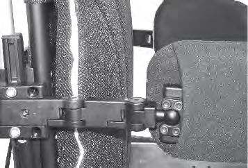
Impressum
   SORG Rollstuhltechnik GmbH + Co. KG
   Benzstraße 3-5
   68794 Oberhausen-Rheinhausen / Germany

   Fon     +49 7254-9279-0
   Fax     +49 7254-9279-10
   Mail    info@sorgrollstuhltechnik.de
   Web     www.sorgrollstuhltechnik.de

   Revision status
   2021-05-26

   Technical status
   We reserve the right to make technical chan-
   ges and misprints. The images can differ from
   the actual individual equipment components.
   The handling is to be carried out accordingly.
   Gender note
   For editorial reasons for better readability, only
   the masculine form is used. Corresponding
   terms apply in the sense of equal treatment to
   all genders and do not represent any valuation.

   Copyright
   All content, especially texts, photographs and
   graphics, are protected by copyright. All rights,
   including copying, publishing, editing and
   translating, are reserved. © by SORG Rollstuhl-
   technik GmbH + Co. KG Benzstrasse 3-5, 68794
   Oberhausen-Rheinhausen / Germany.

        You can find our general terms and condi-
   tions on our order sheets and at www.sorgroll-
   stuhltechnik.de/impressum.

2 von 36                                  Service record Dynamis MV   2021-05-26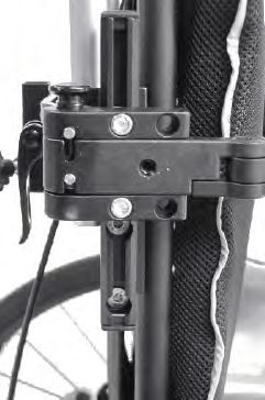
Contents
     1 The wheelchair at a glance                             4    4 Repairs / maintenance / re-use29
                                                                       4.1 Rapairs                  29
     2 General information                                    5       4.2 Spare parts              29
        2.1 General information service booklet               5       4.3 Cleaning                 29
        2.2 Documentation notes                               5       4.4 Disinfection             29
        2.3 Required torques and tools                        5       4.5 Storage                  29
        2.4 Explanation of symbols                            6       4.6 Lifespan                 30
        2.5 General safety information                        7       4.7 Re-use                   30
                                                                       4.8 Disposal                 30
     3 Assemblys                                                8      4.9 Maintenance / inspection 30
        3.1 Wheel assembly                                     8
            3.1.1 Center of gravity(wheelbase/perforated plate)8   5 Technical data                       31
            3.1.2 Adjustment of the seat height by                     5.1 Data and dimensions             31
            changing the position of the caster wheel 8                5.2 Meaning of the labels           32
            3.1.3 Rear seat height, seat inclination           9      5.3 Declaration of Conformity       32
            3.1.4 Caster head tilt                             9
            3.1.5 Replacement / relocation of the caster
            wheel adapters and caster wheels                 10
            3.1.6 Camber                                     10
            3.1.7 Track compensation drive wheels 11
        3.2 ERGO-seat assembly                               12
            3.2.1 General information about the ERGO seat12
            3.2.2 Removal of the ERGO seat                   12
            3.2.3 Axis of rotation seat part / back part13
            3.2.4 Growth in seat depth ERGO seat             13
            3.2.5 Adjusting the seat height                  13
            3.2.6 Increase seat width ERGO unit14
        3.3 Frame assembly                                    15
            3.3.1 Frame widening                             15
        3.4 Back assembly                                     16
            3.4.1 Setting dynamic back                       16
            3.4.2 Back angle adjustment                      16
        3.5 Legrest assembly                                  17
            3.5.1 Adjustment of the legrest                  17
            3.5.2 Adjustment of the depth                    17
            3.5.3 Adjusting the height                       18
            3.5.4 Preset opening angle                       18
            3.5.5 Height adjustment of the calf support18
            3.5.6 Height adjustment of the footrest 19
        3.6 Brakes assembly                                  20
            3.6.1 General information about the brake 20
            3.6.2 Standard parking brake                     20
            3.6.3 Drum brake                                 21
        3.7 Anti-tipper assembly                             22
            3.7.1 Height adjustment                          23
            3.7.2 Length adjustment                          23
        3.8 Tilt bracket assembly                            24
            3.8.1 Mounting                                   24
        3.9 Headrest assembly                                 25
            3.9.1 Height adjustment                          25
            3.9.2 Depth adjustment and dynamics of
             the headrest                                    25
            3.9.3 Adjust the inclination                     25
        3.10 Abduction wedge assembly                         26
            3.10.1 Depth adjustment                          26
            3.10.2 Height adjustment                         26
        3.11 Lateral support assembly                         27
            3.11.1 Nomenclature                              27
            3.11.2 Vertical adjustment                       27
            3.11.3 Horizontal setting                        27
            3.11.4 Fine adjustment of the lateral support
            holder28
            3.11.5 Adaptation to the user                    28

2021-05-26                                       Service record Dynamis MV                               3 von 36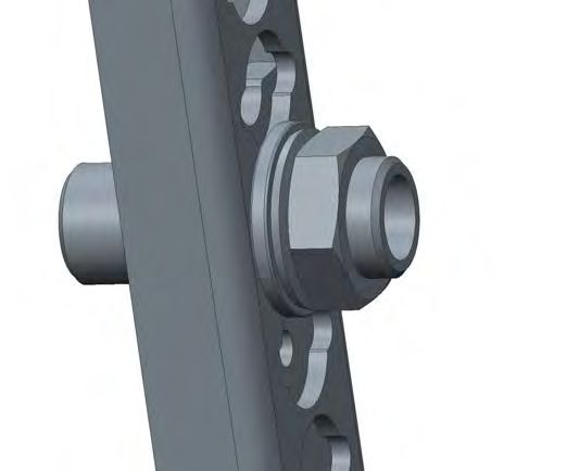
1 The wheelchair at a glance

              2                      1

                                                 1 headrest
                                                 2 push bow
                                                 3 drum brake control lever
     3                                           4 anatomical back cushion
                            4
                                                 5 Ergo-seat
                                                 6 drive wheel
              5                                  7 handrim
                                                 8 anatomical seat cushion
         6                                       9 knee lever brake
     7                                           10 footplate
                                               8 11 caster fork
                                                 12 caster wheel

     9
                                          11

                       12                10

                             14

             15                                  14 headrest
                                                 15 push bow
                                                 16 control lever for drum brake
         16                                      17 star grip for height adjustment of the
                                     18          push handle
17                                               18 armrest
                                                 19 back guide
                                                 20 drive wheel
                                                 21 shock absorbers
         19                                      22 Brake lever of the knee lever brake
                                                 23 caster wheel
                  20

              21

                                22   23

4 von 36                    Service record Dynamis MV                                   2021-05-26
2 General Information
      2.1 General information on the service booklet

     All individual settings, adjustments, repairs and the annual inspection of the wheelchair are
     described below. This requires tools and special expertise. Please leave these adjustments to a
     qualified specialist retailer.

     Adjustments that can be made by the attendant are described in the instructions for use.

     If you have any questions or comments, please contact your specialist retailer or our team (+49
     7254 9279-0).

      2.2 Documentation notes

     Please note:
        • You can find advance booking information on our website at www.sorgrollstuhltechnik.de
        • Information for the user can be found in the instructions for use
        • Maintenance information can be found under: Chapter 4 (Repair / Maintenance / Re-use)

      2.3 Required torques and tools

      Torque required for the following screws:

        •    M5: 5 Nm;
        •    M6: 7 Nm;
        •    M6 (perforated plate) 10 Nm
        •    M8: 20 Nm;
        •    M10 (nut): 25 Nm; (caster wheel)
        •    Thru axle fitting 40 Nm

      Needed tools:

        •    Torque wrench (5-50 Nm)
        •    Open-ended wrench
        •    Reversible ratchet with socket wrench inserts
        •    Hexagon screwdriver
        •    Phillips screwdriver
        •    Slotted screwdriver
        •    Plastic hammer
        •    Side cutter
        •    Thread locking liquid
        •    Bicycle tube repair kit
        •    Workbench / vice with plastic jaws
        •    Special open-end wrench for adjusting the shock absorber

2021-05-26                              Service record Dynamis MV                               5 von 36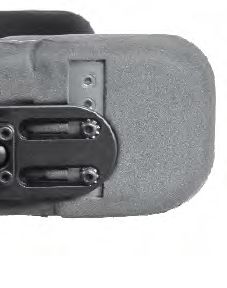
2 General information
    2.4 Explanation of symbols

                      ATTENTION! Warnings for per-
                      sonal safety issues, of the utmost                    Important detail / element
                      importance

                      CORRECT safety relevant setting/                      Correct or proper setting / use
                      handling

                      WRONG adjustment/ handling                            Inadmissible or incorrect setting
                                                                            / use

                                                              (A); (B)      Reference from text to detail
                      PROHIBITED

                      Reference to additional / further
                      reading.

   Handling

                      Push / pull / insert / move / re-                     perspective
                      move

                      Push in a certain direction                           View from above

                      Set or adjust the angle
                                                                            Side view

                      Open / close
                                                                            View from below

                      Turn clockwise
                                                                            Front view

                      Turn counterclockwise
                                                                            Rear view

     1.          1.   Steps to be performed at the
                      same time
                                                                            Attach part
       1.        2.   Steps to be performed in se-
            ;
                      quence
                                                                            Remove part
            2x        Steps to be performed on both
                      sides

6 von 36                                        Service record Dynamis MV                                   2021-05-26
2 General information
2.5 General safety information
Check before every ride:
• Frame, back unit, add-on parts and accessories for visible damage, bends, cracks or mis-
sing / loose screws,
• Wheels / thru axles on tight fit ,
• sufficient tire pressure, tire profile,
• Functionality of the brakes,
• tight fit of the angle adjustment elements / eccentric clamps,
• firm closure of the seat plate / back / foot plate,
• functionality of the anti-tips / seat and back straps,
• whether all previously dismantled parts are reinserted and firmly locked.
There is a risk of injuries (e.g. crushing) on all rotating, rotatable or foldable parts, also
during adjustment and repair work as well as during transport.
All wheelchair parts are to be handled properly. Do not throw or drop removable parts!
Before starting the test, repair or adjustment work, clean / disinfect the wheelchair and
secure it against tipping over and / or falling.
Use only original spare parts.
Safety nuts may only be used once. Safety nuts that have been loosened must be repla-
ced with new ones.
Only regular maintenance of all safety-relevant parts on the wheelchair by a qualified
rehab workshop protects against damage and maintains our manufacturer's warranty.
Lifespan
Use beyond the specified service life leads to an increase in the residual risks and should
only be carried out after careful, qualified consideration by the operator. If the service life is
reached, the user or a responsible person should contact the specialist retailer. There you can
get information about the possibility of reconditioning the product.
Combination with products from other manufacturers
The wheelchair may only be combined with the additional electrical drives approved by the
manufacturer. Restrictions or adjustments as well as the cultivation itself are the responsibility
of the provider of the additional system or the authorized specialist retailer. Please ask the ma-
nufacturer of the additional drives for the requirements.
In the combination of a wheelchair and an additional electric drive, particular loads occur
that can damage the wheelchair. Approach obstacles slowly and overcome them carefully so
that little force is exerted on the caster wheel, drive wheel and the wheelchair as a whole.
2021-05-26 Service record Dynamis MV 7 von 363.1 Wheels assembly
3.1.1 Center of gravity (wheelbase / perforated plate)
(1) To adjust the center of gravity
(1)
• remove both drive wheels,
• remove all screws (A) and nuts
• move the perforated plate into the al-
ternative holes (B).
• Moving must be done in parallel on
both sides.
• Reinstall screws and nuts and tighten
tightly.
(A)
(B)
The parking brakes must be readjusted
after every change to the drive wheels.
Go carefully to the maximum and the
user (!) Desired point of tilt.
The further back you move the caster wheels, the greater the risk of the wheelchair tip-
ping forward when getting in and out.
The further you mount the drive wheels with the perforated plate to the front, the greater the
risk of the wheelchair tipping backwards.
When tilting the seat, please make sure that the gripping point and gripping path are not im-
paired by setting the drive wheels too high.
The drive wheel mount can be adjusted horizontally by up to 60 mm from the most passive po-
sition (0 mm).
3.1.2 Adjustment of the seat height by changing the position of the caster wheel
(2) The front seat height is adjusted via the po- (2)
sition of the caster wheel in the caster fork.
• Completely remove the caster wheel /
caster fork screw connection (A),
• Fasten the caster wheels in the desired
hole (B) on both sides,
• tighten all screws again.
(B)
After every change you have to check the
vertical tilt of the caster head and correct it if
necessary (see chapter caster head tilt).
(A)
Hair, lint, dirt, etc. collect on the bea-
rings of the caster wheels, making the cas-
ter wheels stiff. Remove the caster wheels
at short intervals and thoroughly clean the
forks, axles and sleeves.
Please proceed in the same way with plastic
forks.
8 von 36 Service record Dynamis MV 2021-05-263.1 Wheels assembly
3.1.3 Rear seat height, seat inclination
As a rule, the seat height at the back is selected approx. 2-3 cm lower than the seat height at
the front in order to achieve a safe and comfortable sitting position with good distribution of
the seat pressure and to avoid "slipping forward". However, other settings can also be useful in
individual cases.
• (1) Remove the drive wheels and remo- (1)
ve the quick release axle fitting (A) with
all washers,
• move the quick-release axle fitting in-
cluding all washers into the alternative (A)
holes (B) (B)
• and tighten all screws again. (Tightening
torque of nuts M18 fitting 40 Nm).
• Mount the side parts and put the drive
wheels back into the quick-release axle.
The fittings must protrude equally far out of the perforated plate on both sides. The fittings may
only be unscrewed so far that the lateral distance between the tires at the top and the side panel
is as small as possible, but at least 10 mm.
3.1.4 Caster head tilt
The caster head inclination must be readjusted
after every change to the drive wheel. (2)
For adjusting the caster wheel adapter:
• (3) Loosen all screws (A) (B) on both (A)
sides.
• Bring the adapters into an exactly ver-
tical position by turning the adjusting
washer (C) (using a flat-blade screwdri-
ver) (create an angle).
• Tighten all screws again; Screws (A)
with 9 Nm, screw (B) with 7 Nm (B)
(C)
An incorrectly set caster head inclination can lead to caster wheel flutter and when cor-
nering (due to the wheel caster) to cumbersome "uphill and downhill driving".
2021-05-26 Service record Dynamis MV 9 von 363.1 Wheels assembly
3.1.5 Replacement / relocation of the steering wheel adapters and caster wheels
• (1) Remove the caps on both sides (A),
• remove all screws on both sides (B) (1) (C)
• and remove the spacers if necessary.
• Replace the caster wheel adapters with
new ones and / or move them to the
alternative holes (C).
• Reinsert all screws (including the spa-
cers, if applicable) and tighten them
tightly. (B)
(A)
3.1.6 Camber
You influence through the camber: (2)
• the lateral tipping stability
(B)
• the shoulder drive wheel position and
• the track width of the wheelchair.
(2) To avoid the so-called "eraser effect", we install
the appropriate track compensation (A) at the
factory. If the camber is changed at a later date,
the toe compensation adapter (A) must be repla-
ced with a suitable one (spare part).
With a wheel camber of 8 °, a spacer block is re-
quired to extend the wheelbase (spare part). (C)
Adjust the camber:
• (3) Remove drive wheels,
• Remove the screw connection (A) and
(A)
move it into the alternative holes (B),
• tighten the screw connection again.
(3)
For a camber of 8 °:
• (3+1 next page) remove the screw con- (E)
nection (A),
• remove the screw connection (C),
• move the perforated plate holder (D) by
turning it 180 ° on the outside of the frame
tubes,
• insert the screw connection (C) again and (B)
tighten the screws (C) tightly,
• reinsert the perforated plate with the screw
connection (A) and tighten the screws (A). (A)
The setting may not be possible if you want to
widen the seat, otherwise you will have to unscrew
the quick-release axle fittings too far out of the
perforated plate.
(D)
(C)
10 von 36 Service record Dynamis MV 2021-05-263.1 Wheels assembly
Check / correct the distance between the drive
wheel and the side panel or the clothes guard by (1)
attaching the drive wheel.
The tires on the bike must be at least 10 mm away
from the side panel or the clothing guard. Pay
attention to the same distance left and right! inside out-
(1) For turning the quick-release axle fitting in or (B) side
out:
• Loosen the screw connection of the fitting
(B) (also the lock nut on the inside),
• turn the complete fitting (C) into the re-
quired position and
• Tighten all screw connections again (tigh-
tening torque of nuts M18 fitting 40 Nm).
(D)
Be sure to check the functionality of the knee lever brake and readjust it if necessary.
3.1.7 Track compensation drive wheels
The wheelchair is delivered with the appropriate toe-in, depending on the camber setting and
any installation of the SORG outdoor front end. When changing the camber or retrofitting the
outdoor front end, it may be necessary to change the toe-in.
To change the toe-in:
• Remove drive wheels, (2) (A) (B)
• and remove screw connection (B+C) .
Depending on the attachment variant and the (C)
camber, please follow the instructions on the
following pages.
After changing the toe-in settings:
• reinsert the screw connection (B + C)
and tighten the screws (B) tightly.
Check / correct the distance between the drive
wheel and the side panel or the clothes guard
by attaching the drive wheel.
Be sure to check the functionality of the knee lever brake and readjust it if necessary.
2021-05-26 Service record Dynamis MV 11 von 363.2 ERGO-seat assembly
3.2.1 General information about the ERGO seat
The ERGO seat offers installation and attachment options for anatomical seat and back cushion,
lateral support, lateral pads, armrests, headrests and belt holders.
(1)
3.2.2 Removing of the ERGO-seat
To remove the ERGO seat, the screw connection of the back guide must be removed (2 A). In the
next step, the screw connection on the seat frame must be removed (3 A).
(2) (3)
(A)
(A)
12 von 36 Service record Dynamis MV 2021-05-263.2 ERGO-seat assembly
3.2.3 Axis of rotation seat unit/ back unit
(1)
The axis of rotation should be aligned as close (A)
as possible to the patient's hip joint. We re-
commend using the outer hole (1 B) for a body
height of up to 150 cm and the inner hole (1 A)
for larger body sizes.
(B)
If the screw connection is removed in order to determine a new position, the screw con-
nection must be secured with medium-strength screw locking.
3.2.4 Growth in seat depth ERGO seat
(2)
The seat depth of the ERGO seat can be adjus-
ted by + 2cm.
To do this, the following steps should be ob- (B)
served:
• Remove the seat plate screws. (2 A)
• Bring the seat plate into the desired
position and insert the screws in the (A) (A)
respective holes. (2 B) (C) (C)
• Remove the screws from the seat
center section / side section and (B)
screw them back into the center hole.
(2 C)
• Check all screws to ensure that they are
firmly tightened again.
3.2.5 Seat height adjustment
In preparation, please remove the drive wheels (3)
Remove the screw connection on both sides (A)
(3 A) of the seat support brackets (3 B) and
pull the sleeves in the front screw connections
outwards so that the seat support brackets can
be moved freely.
Put the seat support bracket in position, push
the sleeves back into the selected holes (3 B)
of the seat support bracket and tighten the
screws on both sides.
(B)
2021-05-26 Service record Dynamis MV 13 von 363.2 ERGO-seat assembly
3.2.6 Increase seat width ERGO seat and back unit
(1) (A)
2x
ERGO-back (D)
Loosen the screw connection of the back angle
part (A, B, C) and back middle part (D). Move
the back angle parts so that the desired width is
achieved. Now the previously removed screws
are screwed back in order to reconnect the
central back and the back angle part. Please
repeat the same steps with the other back angle
section. (B)
(C)
(2)
2x
(A)
ERGO-side guard
Loosen the screw connection of the seat gu-
ard (A, B, C) and seat center section. Move the
seat side guard so that the desired seat width is
achieved. Now the previously removed screws (B)
are screwed in again in order to reconnect the
seat side guard with the seat middle part. Please
repeat the same step with the other side guard.
(C)
14 von 36 Service record Dynamis MV 2021-05-263.3 Frame assembly
3.3.1 Frame widening
To widen the frame, first remove the Ergo seat. (1)
(see chapter Ergo seat assembly 3.2.2.).
To widen the frame:
• Remove both drive wheels.
• Remove the screw connections of the
crossbars (1A) on one side.
(A)
• On the same side, remove the hook un-
der the seat support bracket (2A).
• Now pull the frame apart (half the desi-
red widening)
• and reinsert the screws loosely.
• Mount the hook under the seat support
bracket in the new position. (2)
• Vyou can find out analogously with all
screw connections on the opposite side.
• Then tighten the screws again.
(A)
The traverses must be offset at the
same distance on both sides.
2021-05-26 Service record Dynamis MV 15 von 363.4 Back assembly
3.4.1 Setting dynamic back
The back dynamics of the Dynamis TSD can be adjusted with the included SORG open-end
wrench (1).
Please note the following steps:
(1)
1. Increase the counterforce (2): Turn the adjusting nut to the right with the help of the SORG
open-end wrench. This increases the dynamism of the back.
2. Reduce the counterforce (3): Turn the adjusting nut to the left with the help of the SORG
open-end wrench. This weakens the dynamic of the back.
(2) (3)
The nut must always be screwed in at least so far that the steel spring is slightly pretensi-
oned.
3.4.2 Adjustment of the back angle
The basic setting of the back ang- (1)
le can be changed via the row of holes
in the suspension of the spring damping. (B)
The setting can be changed to 90 °, 95 °
and 100 ° from the inside to the outside.
For this purpose, the screw (A) - in this picture in
the setting 90 ° - is loosened and fastened again
with the spring damper in an outer hole (B). Ple-
ase tighten the screw, but not too tight, so that the
spring remains flexible.
(A)
16 von 36 Service record Dynamis MV 2021-05-263.5 Legrest assembly
3.5.1 Adjustment of the legrest
(1)
The legrest, which can be swiveled upwards, is
mounted under the seat frame with the aid of
a traverse and clamping screws.
(2)
(A)
1. When adjusting the legrest, make sure that
the axis of rotation of the legrest (A) is as close
as possible to the anatomical axis of rotation
of the user's knee
After every change to the legrest, check whether the caster wheels can still turn freely
through 360 ° when they are tilted to the front. You may have to make corrections either by
adjusting the caster wheels or by adjusting the leg rests.
3.5.2 Adjustment of the depth
The depth of the legrest can be continuously adjusted up to 8 cm. To do this, please follow the
steps below:
(1)
1. Loosen the clamping screws (A) on the seat
frame, then
2. Adjust the depth as desired.
3. Tighten the screws again and check. (A)
2021-05-26 Service record Dynamis MV 17 von 363.5.3 Adjusting the height
The height of the legrest can be adjusted by (1)
1.5 or 3 cm. To do this, please follow the steps (A)
below:
1. Remove the screws (A) on the journal part,
2. Adjust the height as desired by lifting and
3. Insert the screws again, tighten them and
then check them.
Height adjustment not possible in combination with an abduction wedge.
3.5.4 Preset opening angle
The opening angle of the legrest can be adjus-
ted continuously between 90 ° and 117 ° via a (1)
presetting as follows:
1. Engage the pull latch with a 90 ° turn (A) (B)
2. Loosen the screws (B) on the grid plate on
both sides, inside and outside.
3. Adjust the legrest to the desired position.
4. Tighten the screws again firmly.
(A)
3.5.5 Height adjustment of the calf support
(1)
To change the height of the calf support, ple-
ase follow the steps below:
1. Loosen the screws. (1A)
2. Now move the calf clamping plate and at-
tach the removed elements in reverse order.
3. Make sure that all screws are properly tigh-
tened.
(A)
18 von 36 Service record Dynamis MV 2021-05-263.5.6 Height adjustment of the footrest
(1) the
Adjustment of the distance between the foot e f rom the
and seat plate (LLL) anc of
Dist r edge the
p e t o
With the standard legrest, the distance bet- up plate of the
ween the upper edge of the seat plate and seat r edge
e
upp late
the upper edge of the footplate is changed as fo o t p
follows:
• (2) Remove the two screws (A),
• remove the footplate / s and
• move the footplate (s) along the holes
(B) to the new position (s).
• Reinstall the two screws (A) and tighten (2) (A)
them tightly.
Alternative:
1.Remove the screws (3A)
2. and bring the stirrup to the desired height. (B)
3. Screw in the screws (3A) and the stop parts
(3B) up to the outer tube.
4. Now pull the stirrup down a little
5. and screw in the stop part (3B) completely.
Adjustment of the stop angle of the footplate
(s) (3)
(4) Use the two adjusting screws (B) to adjust (A)
the stop angle of this footplate / s.
• Fold back the footplate (s),
• loosen the lock nuts (A),
• turn the two adjusting screws (B) until (B)
you have reached the desired angle,
• tighten the lock nuts (A) again.
When the footplate (s) is in use, both
adjusting screws must lie firmly against the
tubes (C) of the leg support. It is essential to
avoid an uneven contact point for the adjus- (4)
ting screws.
(A)
(B)
(C)
2021-05-26 Service record Dynamis MV 19 von 363.6 Brakes assembly
3.6.1 General information about the brake
(1+2) Every wheelchair is equipped with two
parking brakes or knee lever brakes. They con-
(1)
sist of brake pressure bolts (A), brake lever (B)
(if necessary with an extension) and adjusting
screws(C).
Parking brakes are used only to lock the (B)
wheels in a rest position. They are not de-
signed to brake the wheelchair while it is in
motion.
The correct functioning of the brakes
can be impaired by:
• tire pressure too low,
• Wetness, dirt, snow, ice, etc.. (C)
• worn tire profile and
• Too great a distance between the brake
pressure bolt and the tire. (D)
(A)
Check the fastening of the brake pressure
bolts on the inside of the wheelchair at regular
intervals (D) (2)
Readjust the brakes after making any
changes to the drive wheels. On a ramp with
a 12.3% (7 °) gradient, the wheelchair's drive
wheels with occupants must not slip when
the parking brake is on.
When the brake is open, the maximum dis-
tance between the brake pressure pin and the
tires is set as follows:
Standard-KLB 21 mm
Pull-to-lock-brake 11 mm
KLB with anti-rollback about 10 mm (C)
Bowden cable brake 6 mm
(Technical changes reserved). max.
21 mm
Technische Angaben beachten!
3.6.2 Standard parking brake
(2) First check the tire pressure of the drive wheels (required information on the tire casing). To
adjust the brake, loosen the two screws (C) on both sides, bring the brake body into the corres-
ponding position and tighten the screws (C) again.
20 von 36 Service record Dynamis MV 2021-05-263.6 Brakes assembly
3.6.3 Drum brake
The braking force of the drum brakes is optimally adjusted by our fitters.
For safety reasons, regular checking of their functionality is required, as permanent use
may require readjustment of the braking force or even the replacement of a Bowden cable
.
(1+2) The following drum brake components
are important for adjusting the braking force:
(1)
(D)
adjusting screw (A), lock nut (B), adjusting
nipple (C), holder (D), inner cable (E), locking
lever (F), clamping nipple (G), brake shoes(H)
Zum Einsetzen des Bowdenzugs:
• (3) place the adjusting nipple (C) with
the adjusting screw (A) and lock nut (B)
at the lower end in the counter holder
(D),
• thread the inner cable (E) through the
clamping nipple (G),
• insert the clamping nipple (G) into the
locking lever (F) and
• push the locking lever (F) slightly for-
ward towards the adjusting nipple (C)
so that there is a slight pull between the
nipples.
• Tighten the clamping nipple (G) tightly. (E) (C) (B) (A)
• Put the wheel back on and check whe-
ther the brake shoes (H) are already (2)
rubbing against the brake body.
• To do this, jack up the wheelchair or (H)
hold it up to the side. The wheel must
be able to turn freely. (F)
• If the brake shoes are already grinding
(without you having operated the ope-
rating lever), loosen the clamping nipple (E) (G)
(G) and again
• give the locking lever (F) more play
• Then tighten the clamping nipple (G)
again
To adjust the braking force:
• loosen the lock nut (B) on the adjusting
screw,
• Tension or slacken the inner cable (E) of (3)
the Bowden cable by turning the adjus- (H)
ting screw (A),
• test the pulling force at the top of the (F)
control lever and
• tighten the lock nut (B) again. (G)
(C) (B) (A)
Possible impairment of the braking force can
result from incorrectly adjusted pulling force of
the Bowden cable, defective Bowden cable, or
dirty brake bodies / brake shoes.
(E) (D)
2021-05-26 Service record Dynamis MV 21 von 363.7 Anti tipper assembly
3.7.1 Height adjustment
• (1) Remove the screw (A), (1)
• pull the anti-tipper bar (C) in the holder (A)
(A) down a little,
• move the screw (A) to the desired posi-
tion (B)
• and close it again.
(B)
Alternatively, you can turn the holder by 180 °:
(2) If you want to set the anti-tipper particu-
larly low, you can turn the anti-tipper holder
(C)
(A) by 180 °. To do this, remove the two screws
(E) and the screw (F), remove the anti-tipper
bar (D) and turn it 180 °, screw the anti-tipper
bracket firmly back onto the frame tube, insert
the anti-tipper bar back into the bracket and
position it according to your requirements
using the screw (F) in the holes (1B). (2) (F)
(A) (E)
(B)
(D)
(C)
3.7.2 Length adjustment
(3) If you have adjusted your wheelchair very (3)
actively and the anti-tipper sticks out too far (C)
back, you can shorten the anti-tipper bar. (A)
• Remove the anti-tipper wheel with hol-
der (C) with the screw (B),
• Use a suitable saw to shorten the anti-
tipper bar to the desired length
• and put the anti-tipper wheel with hol- (B)
der back on.
• Put the screw (B) in the appropriate
hole (A) and tighten it again.
22 von 36 Service record Dynamis MV 2021-05-263.8 Tilt bracket assembly
3.8.1 Mounting
(1) For retrofitting a tilting bracket: (1)
• Remove the cap on the underside of the
frame tube,
• guide the tilt bracket (A) into the frame
tube from below and (B)
• screw it tight with the screw (B) in the
frame.
It is not possible to mount the tilt bar and anti- (A)
tipper on the same side of the frame at the
same time.
2021-05-26 Service record Dynamis MV 23 von 363.9 Headrest assembly
3.9.1 Height adjustment
(1)
To adjust the height of the headrest, loosen
the clamping lever (A) on the square tube.
Move the headrest up or down to the desired
position and tighten the clamping lever again.
(A)
3.9.2 Depth adjustment and dynamics of the headrest
1st. Option: To adjust the depth of the head- (1)
rest, loosen the two screws (1A) on the square
tube. Next move the headrest slide forwards or
backwards and screw everything tight again.
2nd. Option: Use the adjusting rings (2A) to
adjust the depth of the headrest. Loosen the
screw connection of the adjusting rings, put
the headrest in the desired position and fasten
the adjusting rings again. (A)
(2)
(A)
3.9.3 Adjust the inclination
The inclination of the headrest can be brought (1)
into the desired orientation by loosening the
three screws (A) on the spherical head and
then adjusting the shaped head part. The
screws must then be tightened again.
(A)
24 von 36 Service record Dynamis MV 2021-05-263.10 Abduction wedge assembly
3.10.1 Depth adjustment
Adjust the height of the abduction wedge using the star grip.
(1) (2)
1. 2.
2.
1.
3.10.2 Height adjustment
1. Open the star grip and pull out the abduc- (1)
tion wedge completely.
2. Remove the clamping cone and pull out the
star grip with the threaded rod.
3. Set the desired height and
4. Put everything back together in reverse
order.
The protruding adjustment part (2 A) must
now be sawed off.
(2)
(A)
(A)
2021-05-26 Service record Dynamis MV 25 von 363.11 Lateral support assembly
3.11.1 Nomenclature
(1) The pads are made up of the following (1)
(A) (B)
parts:
• (A) Connection
• (B) Lateral support pads
• (C) Lateral support holder
• (D) Locking hinge
• (E) Stiffening angle
(D)
(E)
(C)
3.11.2 Vertical adjustment
(2) The vertical adjustment of the pads is made (2) (C) (3)
on the one hand by moving the locking joint
(A). Loosen the screws (B), move the locking (B)
joint into the desired position, tighten the
screws (B) again. (H)
(B)
(E)
Vertical adjustment (A)
(2) The vertical adjustment of the pads can
also be done by turning the C-rail (C). Com-
pletely remove the locking joint (A) using the (D)
screws (B). Remove screws (D), turn C-rail 180
°, reinsert screws (D) and tighten. Mount the
locking joint (A) on the C-rail again using the
(A)
screws (B) and tighten the screws (B).
Another possibility is to adjust the height by
moving the stiffening bracket (E)
3.11.3 Horizontal setting
(4) The horizontal adjustment can be done on (4) (5)
the one hand by offsetting the locking joint.
Remove the screws (4E), move the locking joint
into the holes (4I) (or vice versa), reinsert the (G)
screws and tighten firmly. (E) (I)
Horizontal setting
(5) The horizontal adjustment can also be
done by moving the pad. Remove covers,
loosen screws (5G), move upholstery, tighten
screws again, put covers back on.
Horizontal extension
(6) An additional horizontal extension can be
achieved by inserting an extension piece (spare (6) (C)
part). Remove screw (6C), insert extension pie-
ce and screw tight again at both ends.
26 von 36 Service record Dynamis MV 2021-05-263.11 Lateral support assembly
3.11.4 Fine adjustment of the lateral support holder
(7) (A)
(7) Die Feinjustierung des Spiels zwischen Ver-
schlussgelenk und Pelottenhalter erfolgt über
die Justierschraube (A).
3.11.5 Adaptation to the user
(8)
(8) When all positioning and extension work
has been carried out, close the pads, align the
joints in the required position and tighten all
(A)
joint screws (6A) firmly. Fix the ball joint by
tightening the four screws (B).
2021-05-26 Service record Dynamis MV 27 von 364 Repairs / maintenance / re-use
4.1 Repairs
Repairs are to be carried out by the specialist retailer.
4.2 Spare parts
Only original spare parts may be used. You can obtain these from your specialist retailer.
The spare parts list can be downloaded from www.sorgrollstuhltechnik.de or requested from us.
For a correct delivery of spare parts, the serial no. of your wheelchair. It is located on the label
on the frame.
4.3 Cleaning
Clean the wheelchair and all components regularly with a mild household cleaning agent on a
water basis and then dry it thoroughly.
In addition, clean the drive and caster wheels and remove dirt and contamination (e.g. hair, etc.)
from the axles.
Wash textile parts:
Care instructions:
Wipe synthetic leather, straps and other upholstery:
Care instructions:
4.4 Disinfection
Before each disinfection, cleaning must be carried out. Use a common household water-based
agent for disinfection. Observe the instructions for use of the respective manufacturer.
4.5 Storage
• Perform cleaning
• Fold the folding wheelchair (if available)
• Set the seat tilt (if available) to 90 °
• If necessary, pack removable textile parts in foil or similar
• Secure the wheelchair against rolling away and soiling
• Storage in a dry environment without aggressive environmental influences
28 von 36 Service record Dynamis MV 2021-05-264 Repairs / maintenance / re-use
4.6 Lifespan
The expected normal service life, depending on the intensity of use and the number of re-uses,
is 5 years. For this purpose, the product must be used for its intended purpose and intended
use, the specifications in the instructions for use must be followed and all maintenance and ser-
vice intervals must be observed.
The product can be used beyond this period if it is in a safe condition. This usual, theoretical
service life is not a guaranteed service life and is subject to a case-by-case check by the specia-
list retailer, as is the reusability.
Use beyond the specified service life leads to an increase in the residual risks and should only be
carried out after careful, qualified consideration by the operator.
The service life can also be shortened depending on the frequency of use, the operating envi-
ronment and the care.
The usual service life does not refer to wearing parts such as textile parts, wheels and plastic
parts that are subject to material-specific aging and / or wear.
This specified service life does not constitute an additional warranty or guarantee.
4.7 Re-use
Before re-use, a complete inspection according to the checklist must be carried out by a quali-
fied specialist retailer as well as complete cleaning and disinfection. We recommend replacing
all upholstery and textile parts for use by a new user.
4.8 Disposal
The wheelchair may only be disposed of with the approval of the sponsor. The wheelchair must
be disposed of in accordance with the applicable national statutory provisions.
4.9 Maintenance / inspection
For safety reasons and to maintain product liability, an inspection by your specialist retailer is re-
quired at least once a year. This must be carried out and documented according to the checklist
on the following page.
2021-05-26 Service record Dynamis MV 29 von 364 Repairs / maintenance / re-use
Maintenance and care checklist (user)
Inadequate or neglected maintenance of the wheelchair represents a significant safety
risk.
Before every drive:
Check if:
• Frame, back unit, add-on parts and accessories for visible damage, bends, cracks or mis-
sing / loose screws,
• Wheels / thru axles on tight fit ,
• sufficient tire pressure, tire profile,
• Functionality of the brakes,
• tight fit of the angle adjustment elements / eccentric clamps,
• firm closure of the seat plate / back / foot plate,
• Functionality of the anti-tipper / seat and back straps,
• whether all previously dismantled parts are reinserted and firmly locked.
Every 3 months:
(earlier depending on driving performance)
Check if:
• Screw connections for a tight fit,
• Weld seams, attachments and accessories for hidden damage, bends or cracks,
• Tire tread,
• the firm fit of third-party systems (if available).
Clean and oil all moving parts.
If you discover any deficiencies during maintenance, please contact your specialist retailer
immediately and stop using the wheelchair.
Annual inspection checklist (specialist retailer)
Copy template (available for download at www.sorgrollstuhltechnik.de/downloadportal)
To prepare:
clean
Check if:
Frame, back unit, add-on parts and accessories checked for damage, bending, cracks and
corrosion,
fastening screws for completeness and tight fit,
caster and drive wheels as well as the associated add-on parts checked for condition, func
tionality and running properties,
spokes for tight fit and completeness,
Brakes cleaned and serviced,
Locking mechanisms (tripod springs of the push handles, quick release axles, eccentric
clamps, etc.) checked for functionality,
Anti-tipper checked for tight fit and functionality.
Oil:
Moving parts and bearings are oiled
Final check:
Functional check of all mechanical adjustment devices carried out
30 von 36 Service record Dynamis MV 2021-05-265 Technical data
5.1 Data and dimensions
Model: Dynamis MV
Type: 793
Dimensions ± 5%
Description Measurements Comment
seat width (SW) Ergo-seat 320 - 500 mm | in 20 mm steps growing by 40 mm
seat depth (SD) Ergo-seat 340 - 520 mm | in 20 mm steps growing by 20 mm
back height (BH) Underframe 430 or 500 mm
Ergo-seat 400-650 mm | in 50 mm steps
back unit: adjustable in depth by + 40 / -20
mm
back angle default setting 90° / 95° / 100°
dynamic from the preset angle up to 120 °
lower leg length 220-450 mm Upper edge of seat plate to foot plate
ETRTO wheel size at 20'' Ø 451 mm
ETRTO wheel size at 22'' Ø 489 mm
ETRTO wheel size at 24'' Ø 540 mm
Handrim diameter
at 20'' Ø 444 mm
at 22'' Ø 481 mm
at 24'' Ø 533 mm
handrim Ø 19 mm Pipe diameter
camber 0°, 2°, 5°, 8°, 11°
seat height (SH) front min. 380 mm The seat heights are measured from the top
seat height (SH) front max. 520 mm edge of the seat to the floor, WITHOUT the
seat height (SH) back min. 325 mm seat cushion.
seat height (SH) back max. 585 mm
overall width min. SB + 200 mm
max. SB + 405 mm
overall length min. 875 mm
max. 1135 mm without outdoor front end
Total height (including push min. 1045 mm
handle in 45 ° position) max. 1320 mm
Capacity max. 90 kg
Permissible incline 12,3% = 7° at 0 ° inclination of the back angle
Permissible slope 12,3% = 7°
steadiness 12,3% = 7°
Turning circle about 1050 mm depending on the wheelchair size
Individual weights drive wheels 0,97 - 2 kg depending on the design and size
tires Commercially available pneumatic tires sizes 1 ", 1 3/8" or puncture-proof tires (same dimensions),
tire pressure usually 3-10 bar.
Corrosion protection Material Stainless steel, aluminum
Coating Powder coating, galvanizing
Service life 3 years if the wheelchair is not used excessively
lifespan 5 years
normative requirements The wheelchair meets the requirements of ISO 7176-8 and the requirements against ignition
Minimum empty weight. Roadworthy 20,35 kg Frame size 1, seat frame, 22 '' wheels with
with RB 300 drum brakes, PU caster wheels, legrests, push
mm, 20 '' rear bow
wheels, 5 '' PU
caster wheels
2021-05-26 Service record Dynamis MV 31 von 365 Technical data
5.2 Meaning of the labels
The meaning of the individual labels results directly from the respective text at the relevant
point.
If the nameplate is damaged or lost, a new label can be obtained from SORG Rollstuhltechnik.
Label:
Manufacturer logo
Manufacturer address
Reference to pro-
Reference to duct literature
manufacturer
serial number Reference to a
passed crash test
seat width
according to ISO
7176-19
CE-mark
max.
Type number Model name seat capacity Construc- back height
depth tion year
5.3 Declaration of Conformity
SORG Rollstuhltechnik declares that the Dynamis MV product is a class 1 device and that it
complies with the relevant provisions of EU Guideline (EU) 2017/745 on medical products.
This was verified by a conformity assessment procedure in accordance with the
medical device guidelines.
This declaration loses its validity if changes are made to the product that have not been approved
by SORG Rollstuhltechnik .
32 von 36 Service record Dynamis MV 2021-05-26Notes: 2021-05-26 Service record Dynamis MV 33 von 36
Notes:

34 von 36    Service record Dynamis MV   2021-05-26
Notes:

2021-05-26     Service record Dynamis MV   35 von 36
Service record Dynamis MV

                            SORG Rollstuhltechnik GmbH + Co. KG
                                                   Benzstraße 3-5
                                68794 Oberhausen-Rheinhausen
                                                        Germany
                                             Fon +49 7254 9279-0
                                            Fax +49 7254 9279-10

                                     info@sorgrollstuhltechnik.de
   Retailer stamp                     www.sorgrollstuhltechnik.de
You can also read