Digital Media Fab Lab - CNC MACHINING DEMONSTRATION ADVANCED PROTOTYPING: Reverse/Flip Machining for Two-Sided Objects
←
→
Page content transcription
If your browser does not render page correctly, please read the page content below
DocuSign Envelope ID: FC8711A1-6BE3-4050-8595-7482CA26E425

    D i g i tal M e d i a Fab L ab
    C N C M A C H I N I N G D E M O N ST R AT I O N
    A D V A N C E D P R OTOT Y P I N G : R e v e r s e / F l i p M a c h i n i n g f o r Tw o -S i d e d O b j e c t s
DocuSign Envelope ID: FC8711A1-6BE3-4050-8595-7482CA26E425

DocuSign Envelope ID: FC8711A1-6BE3-4050-8595-7482CA26E425

                                                             D i g i tal M e d i a Fab L ab
                                                             C N C M A C H I N I N G D E M O N ST R AT I O N
                                                             A D V A N C E D P R OTOT Y P I N G : R e v e r s e / F l i p M a c h i n i n g f o r Tw o -S i d e d O b j e c t s
DocuSign Envelope ID: FC8711A1-6BE3-4050-8595-7482CA26E425

                                                                  contents
                                                             09   To o l pa t h P r o g ra m m i n g

                                                             33   M a t e ri a l P r e pa ra t i o n

                                                             41   Machine Setup and Software

                                                             45   Prototype

                                                             55   Design Review

                                                             61   P r o ce s s O n l y - To o l pa t h P r o g ra m m i n g

                                                             67   R e f e r e n ce s

                                                             71   G N U G e n e ra l P u b l i c L i ce n s e
DocuSign Envelope ID: FC8711A1-6BE3-4050-8595-7482CA26E425

                                                             To o l pa t h P r o g ra m m i n g
DocuSign Envelope ID: FC8711A1-6BE3-4050-8595-7482CA26E425

                                                                                                                                                                                                                                                                                                                                        11

                                                                                                                                                                      Toolpath Programming in Autodesk Fusion360 for Machining with a Carbide3D Nomad 883 Pro CNC Machine

                                                                                                                                                                         Open a 3D Model in Autodesk Fusion360

                                                                                                                                                                           Setup the Program with Machine and Material Information
                                                                                                                                                                           Change Workspace to < Manufacture >
                                                                                                                                                                           On the top toolbar, choose Setup < New Setup >
                                                                                                                                                                           On the Setup toolbar, < Setup > Tab, select the machine < 3-axis–Gantry with Moving-Table >
                                                                                                                                                                           Choose and Set, Setup parameters, Work Coordinate System, and Select Model
                                                                                                                                                                           On the Setup toolbar, < Stock > Tab, set the Material Stock Size
                                                                                                                                                                           On the Setup toolbar, < Post Process > Tab, specify Program identity, and Machine Work Coordinate System settings

                                                                                                                                                                      The Demonstration Object program has two Setups, one for each side of the object. The difference between the two Setups is the point on the material stock
                                                                                                                                                                      that the Work Coordinate System is aligned to. The placement of the Work Coordinate System defines the (0,0) reference point location on the material to be cut.

                                                                                                                                                                        Side 00 – Setup 12
                                                                                                                                                                          On the Setup toolbar < Setup > Tab, < Work Coordinate System > setting, we chose to place the (0,0) location at the top, bottom left corner of the material
                                                                                                                                                                          stock
                                                                                                                                                                          On the Setup toolbar < Stock > Tab, we set the stock size to the size of the material to be cut and set the model to be centered within the material stock

                                                                                                                                                                          On the Setup toolbar < Post Process > Tab, we wrote a descriptive Program Name and Comment to reference during future iterations

     One way to create a multi-sided object through automated Reductive Manufacturing is by designing a single program that includes a material part reversal. The
     following information demonstrates the process of programming with Autodesk Fusion360 for rapid prototyping with a Carbide3D Nomad 883 Pro CNC Machine.

     To create the Demonstration Object, we (1) set a design objective, (2) designed an object, (3) programmed toolpaths with Autodesk Fusion 360, (4) prepared the
     material stock, (5) processed material stock with a Carbide3D Nomad 883 Pro CNC Machine, (6) refined toolpaths, and (7) created the final prototype object.

        Design Objective: To efficiently create a sustainable fabrication process for a multi-sided one-off object, intended for rapid design evolution.

           Minimal Material Investment and Waste
           100% biodegradable/clean/sustainable/plant-based prototype material
           Closed-Loop Waste Stream
           Minimal Effort Towards Unnecessary Action
           Create a Version 01 Prototype without fabricating a material stock jig                                                                                                        - Side 00 _ Setup 12, detail of Setup Tab. Autodesk Fusion 360.
DocuSign Envelope ID: FC8711A1-6BE3-4050-8595-7482CA26E425

    12                                                                                                                                                                                                                                                            13

                                                                                               Side 01 – Setup 13
                                                                                               Side 01 has a different Work Coordinate System. We chose to flip the material along the x-axis. To maintain the orientation of the geometry on each side of the
                                                                                               object, we programmed the top right corner of the material stock to be the (0,0) location. The < Stock > Tab information is identical to Side 00, and the < Post
                                                                                               Process > Tab Program Name/Number is adjusted slightly                    ,

                      - Side 00 _ Setup 12, detail of Stock Tab. Autodesk Fusion 360.

                                                                                                                - Side 01 _ Setup 13, detail of Setup Tab. Autodesk Fusion 360.

                      - Side 00 _ Setup 12, detail of Post Process Tab. Autodesk Fusion 360.                    - Side 01 _ Setup 13, detail of Stock Tab. Autodesk Fusion 360.
DocuSign Envelope ID: FC8711A1-6BE3-4050-8595-7482CA26E425

    14                                                                                                                                                                                                                                                                                                                           15

                                                                                                                                                                     Create a Custom Tool Bit or Choose one from the Tool Library
                                                                                                                                                                     There are several ways within Autodesk Fusion360 to access the tool library for the creation of a Tool Bit. You can either do this before programming the
                                                                                                                                                                     toolpaths, or during the Setup unique to the model.

                                                                                                                                                                     Before Toolpath Program
                                                                                                                                                                     Open the Tool Library by choosing Manufacture < Manage < Tool Library
                                                                                                                                                                     On the left side toolbar, select All < Local < Library
                                                                                                                                                                       On the interior panel, click the New Tool (“+”) icon
                                                                                                                                                                         Choose the end mill type and define the Tool Bit specifications in the General, Cutter, and Shaft Tabs                 &

                          - Side 01 _ Setup 13, detail of Post Process Tab. Autodesk Fusion 360.
         While working towards the ideal settings, toolpaths, and simulations, we created several Setups. The Side 00 _ Setup 12, and Side 01 _ Setup 13 are those
         contained within the code utilized for the creation of the Demonstration Object Basswood Prototype. Information about previous Setups and prototyping
         iterations are contained within the Prototype section of this demonstration

                                                                                                                                                                                - Tool Library, New Tool, detail of End Mill types. Autodesk Fusion 360.

                                                                                                                                                                                 - Tool Library, New Tool, General Tab. Autodesk Fusion 360.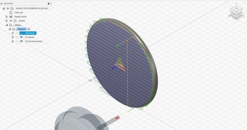
DocuSign Envelope ID: FC8711A1-6BE3-4050-8595-7482CA26E425

    16                                                                                                                                                                                                                                             17

                                                                                                                                                                               In the Holder Tab < set Holder

                       - Tool Library, New Tool, detail of End Mill types. Autodesk Fusion 360.                                                                                       - Tool Library, New Tool, Holder Tab. Autodesk Fusion 360.

                                                                                                                                                                               In the Feed & Speed Tab < set Spindle speed and Cutting feedrate
               Custom Tool Bits can be modified while managing the Tool Library. Open the Tool Library by choosing Manufacture < Manage < Tool Library. On the
                                                                                                                                                                                  References
               left side toolbar, select All < Local < Library. Select the Tool Bit, right click, for < Edit Tool >, < Copy Tool >, < Duplicate Tool >, < Renumber Tool >, <
                                                                                                                                                                                  Carbide3D Nomad 883 Pro Machine Specifications
               Delete Tool >
                                                                                                                                                                                  Carbide3D Nomad 883 Pro Feeds & Speeds Chart

                       - Tool Library, Local, Library, detail of possible Tool Bit modifications. Autodesk Fusion 360.                                                                - Tool Library, New Tool, Holder Tab. Autodesk Fusion 360.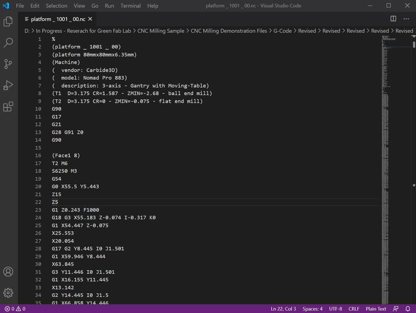
DocuSign Envelope ID: FC8711A1-6BE3-4050-8595-7482CA26E425

    18                                                                                                                                                                                                                                                                                      19

           During Toolpath Program
           Begin a toolpath program by choosing Manufacture < (2D/3D/Drilling/Multi-Axis) < choose a tool process
           On the toolpath menu < Tool > tab, choose < Select… > to open the Tool Library
           On the left side toolbar, select All < Local < Library
             On the interior panel, click the New Tool (“+”) icon
               Choose the end mill type and define the Tool Bit specifications in the General, Cutter, and Shaft Tabs   &

                                                                                                                                   - Tool Library, New Tool, detail of End Mill types. Autodesk Fusion 360.

                                                                                                                            Custom Tool Bits can be modified while managing the Tool Library. Open the Tool Library by choosing Manufacture < Manage < Tool Library. On the
                                                                                                                            left side toolbar, select All < Local < Library. Select the Tool Bit, right click, for < Edit Tool >, < Copy Tool >, < Duplicate Tool >, < Renumber Tool >, <
                                                                                                                            Delete Tool >           .

                      - Tool Library, New Tool, detail of End Mill types. Autodesk Fusion 360.

                      - Tool Library, New Tool, General Tab. Autodesk Fusion 360.                                                  - Tool Library, Local, Library, detail of possible Tool Bit modifications. Autodesk Fusion 360.
DocuSign Envelope ID: FC8711A1-6BE3-4050-8595-7482CA26E425
20 21
In the Holder Tab < set Holder Program a Toolpath
Begin a toolpath program by choosing Manufacture < (2D/3D/Drilling/Multi-Axis) < choose a toolpath process
On the toolpath menu < Tool > tab, choose < Select… > to open the Tool Library
Choose a Tool Bit from the Tool Library OR program a custom Tool Bit
Set the Speeds & Feeds. Speeds & Feeds will automatically set to the Tool Bit’s settings. To modify a preset Speed or Feed, enter adjustments on the < Tool
> tab
On the toolpath menu < Geometry > tab, select the area to be machined, and specify any other additional parameters (Stock Contours, Tool Containment,
Offset Distance, Contact Point Boundary, Rest Machining, Tool Orientation, etc.)
On the Toolpath menu < Heights > tab, set distance values for the Tool Bit movement between processes, processing heights and depths
On the Toolpath menu < Passes > tab, set the variables while taking into consideration the Tool Bit’s workload and the desired aesthetic
On the Toolpath menu < Linking > tab, optimize the machining process, leads, and transitions
The Toolpath Program for the Demonstration Object contains eight toolpaths; four on each side. To decide on a toolpath process, consider the desired form
and material finish. Namely, A PCB circuit board may require a single toolpath on each side for the formation of channels but, a three-dimensional metal object
with holes may require clearing, drilling, finishing, and profiling. Beyond functionality, toolpath processes can add aesthetic and conceptual value to the object
produced.
Stock Contours, Tool Containment, Offset Distance, Contact Point Boundary, Rest Machining, Tool Orientation
Side 00 – Setup 12’s Spiral toolpath contains precise edge settings. Notice the differences in the two simulated machining processes:
Tool Containment – Tool center on boundary & on
Tool Containment – Tool center on boundary + .04mm Offset Distance on &
- Tool Library, New Tool, Holder Tab. Autodesk Fusion 360.
In the Feed & Speed Tab < set Spindle speed and Cutting feedrate
References
Carbide3D Nomad 883 Pro Machine Specifications
Carbide3D Nomad 883 Pro Feeds & Speeds Chart
- Tool Library, New Tool, Holder Tab. Autodesk Fusion 360. - Toolpath Settings, Tool Containment: Tool center on boundary. Autodesk Fusion 360.DocuSign Envelope ID: FC8711A1-6BE3-4050-8595-7482CA26E425
22 23
- Toolpath Settings, Tool Containment – Tool center on boundary + .04mm Offset Distance. Autodesk Fusion 360.
- Toolpath Simulation, Tool Containment: Tool center on boundary. Autodesk Fusion 360.
- Toolpath Simulation with Material Visible, Tool Containment: Tool center on boundary. Autodesk Fusion 360. Tool Containment. Tool center on boundary.
Autodesk Fusion 360. - Toolpath Simulation, Tool Containment: Tool center on boundary + .04mm Offset Distance. Autodesk Fusion 360.DocuSign Envelope ID: FC8711A1-6BE3-4050-8595-7482CA26E425
24 25
Generate Toolpaths
Choose the Setup or Toolpath to be generated
In the < Manufacture > Workspace, < Actions > Tab, choose < Generate >
For the Demonstration Object, we refined settings, toolpaths, and simulations multiple times in order to maintain the integrity of the 3D Model design.
Toolpaths can be generated individually or as a group. Generating toolpaths individually may become necessary as the need to refine variables within the
toolpath arise (see Prototype section, ).
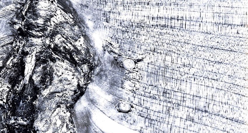
Simulate Toolpaths
Choose the Toolpath or Setup to simulate
On the < Manufacture > toolbar, < Actions > Tab, choose < Simulate >
On the Simulate Menu < Display > Tab, set the Tool, Toolpath, and Stock visibility
On the Simulate Menu < Info > Tab, view Tool Bit position during simulation, Toolpath Information, Machining Time, Machining Distance, Operations, and
Tool Changes
Located at the bottom of the Workspace above the < Navigation Toolbar >, controls to < Start > the simulation, < Move > between toolpaths, and change <
Speed > are available
Demonstration Object toolpath previews and toolpath simulations - on -
- Toolpath Simulation with Material Visible, Tool Containment: Tool center on boundary + .04mm Offset Distance. Autodesk Fusion 360.
Choose to set settings according to the intended aesthetic. To smooth transitions between surfaces on an object, consider adding a finishing toolpath.
The Demonstration Object’s Side 00 – Setup 12’s program contains three “roughing” toolpaths (Face, Spiral, Morphed Spiral) that remove material bulk, before
a final “finishing” toolpath (Parallel ). The finishing toolpath cleans and refines the edges on the surface. An ideal finishing toolpath will prepare the
surface for a minimal amount of hand finishing.
- Paused Toolpath Simulation with material stock visible, and colorization set to code by operation. Green; Facing. Blue; Spiral. Purple; Parallel. Autodesk Fusion
360. - Demonstration Object, Side 00 _ Setup 12, Setup Toolpath Preview of Facing, Spiral, Morphed Spiral, and Parallel Finishing. Autodesk Fusion 360.DocuSign Envelope ID: FC8711A1-6BE3-4050-8595-7482CA26E425
26 27
- Demonstration Object, Side 00 _ Setup 12, Spiral Toolpath Preview. Autodesk Fusion 360. - Demonstration Object, Side 00 _ Setup 12, Parallel Finishing Toolpath Preview. Autodesk Fusion 360.
- Demonstration Object, Side 00 _ Setup 12, Morphed Spiral Toolpath Preview. Autodesk Fusion 360. - Demonstration Object, Side 01 _ Setup 13, Facing Toolpath Simulation with Material Visible. Autodesk Fusion 360.DocuSign Envelope ID: FC8711A1-6BE3-4050-8595-7482CA26E425
28 29
- Demonstration Object, Side 01 _ Setup 13, Toolpath Simulation with Material Visible. Autodesk Fusion 360.
- Demonstration Object, Side 01 _ Setup 13, Parallel Finishing Toolpath Simulation with Material Visible. Autodesk Fusion 360.
Post Process
Create the Program
Choose the Setup or Toolpath to Post Process
On the < Manufacture > toolbar, < Actions > Tab, choose < Post Process >
In the < Post Process > window, set < Post Configuration > to < Carbide 3D (Grbl) / Carbide3D >
Choose the < Output folder >
Set < Program Settings >
< Post >
Setup or Toolpath
Programs that contain multiple WCS (Work Coordinate System) locations, will require separate code files for each WCS location. The Demonstration Object
program has two WCS locations; Side 00 – Setup 12, and Side 01 – Setup 13. After refining the toolpaths, we chose to post the program for Side 00 – Setup 12,
as a single program to include all four toolpaths. Posting all four toolpaths for one side optimizes the efficiency of transitions (retraction, plunge, and travel)
between machining operations (see Toolpath Preview, yellow and red lines .
< Output Folder >
It is recommended to choose a folder that can be transferred to the desktop of the computer attached to the Carbide3D Nomad 883 Pro. For the Demonstration
Object, code was saved locally, transferred to a external drive, transferred to the computer attached to the Carbide3D Nomad 883 Pro, and deleted when
complete.
- Demonstration Object, Side 01 _ Setup 13, Morphed Spiral Toolpath Simulation with Material Visible. Autodesk Fusion 360.DocuSign Envelope ID: FC8711A1-6BE3-4050-8595-7482CA26E425
30 31
Source Code Errors
The computer system we choose to utilize while programming toolpaths has Visual Studio Code installed for viewing code. While refining settings and
toolpaths, it is helpful to reference an external code editor to see errors or make modifications to the .nc file .
- Post Process Settings. Autodesk Fusion 360.
File Organization
There is value in organizing files clearly, especially when developing a new process or prototyping something for the first time that may inform other projects.
The Demonstration Object program files are nested; revised code is contained within the previous file folder, & .
- The Demonstration Object’s Side 00 _ Setup 12, Toolpath Program. Visual Studio Code.
- Demonstration Object Program File Folders
- Demonstration Object Program File Folders, detail of nesting revised codeDocuSign Envelope ID: FC8711A1-6BE3-4050-8595-7482CA26E425
M a t e ri a l P r e pa ra t i o nDocuSign Envelope ID: FC8711A1-6BE3-4050-8595-7482CA26E425
35
Material Preparation: Adobe Illustrator, Universal Control Panel, Universal Laser Systems PLS6.75
To prepare material stock for the Demonstration Object, we chose to design a square in Adobe Illustrator to be laser cut out of a ¼” piece of basswood with the
Universal Laser Systems PLS6.75. The dimensions of the square are 80mm x 80mm x 6.5mm; at this scale, the material stock is approximately 1mm larger than the
Demonstration Object 3D model on all sides. This tolerance aligns with the Demonstration Object Design Objective, Minimal Material Investment and Waste.
Open Adobe Illustrator
Set Artboard size to material size
- Artboard size, W (width) and H (height) equal to the basswood material size. Adobe Illustrator.
Create a Positioning Box < Rectangle Tool > set dimensions to material size
Set the stroke to .001
Set the stroke color to R: 255 G: 255 B: 0
To maintain alignment with the Design Objectives of the Demonstration Object, the material stock for the prototype was created from a piece of basswood
material, found in the Digital Media Fab Lab, and intended for use during prototyping by Florida State University, Department of Art, Students, Faculty, and Staff.
To prepare the material for CNC Machining, we (1) designed a material stock contour and positioning box with Adobe Illustrator, then (2) processed material with
a Universal Laser Systems PLS6.75 CO2 Laser Cutter.
Universal Laser Systems PLS6.75
The information on Material Preparation (pages 35 - 38) functions as a supplemental resource to the Digital Media Fab Lab, Universal Laser Systems
PLS6.75, Machine Demonstration and Training. Understanding the safety information and receiving a Machine Demonstration and Training from a qualified
Digital Media Fab Lab staff is mandatory prior to engaging any and all technology, equipment, and machines within the Digital Media Fab Lab, Department
of Art, 530 W Call Street, Fine Arts Building 422, Tallahassee, Florida 32306-1150.
References
Schedule a Machine Demonstration and Training
Digital Media Fab Lab Scheduling Calendar
Universal Laser Systems PLS6.75
Digital Media Fab Lab — How To — Setup a File for Laser Cutting
Approved Materials
- Positioning box, scaled equally to material size with color mapping information. Adobe Illustrator.DocuSign Envelope ID: FC8711A1-6BE3-4050-8595-7482CA26E425
36 37
Create the stock contour to be cut
Set the stroke to .001
Set the stroke color to R: 255 G: 0 B: 0
- Stock contour to be cut with color mapping information. Adobe Illustrator.
File < Save to External Drive
- Positioning box and material stock contours, repositioned to location of material stock. Universal Control Panel.
Open a vector file in Adobe Illustrator on the computer attached to the Universal Laser Systems PLS6.75
File < Print
Set the < Media Size > to < Defined by Driver >
Set the < Printer > as < ULS 6.75 >
Choose < Print >
Open Universal Control Panel
Align material stock onto the honeycomb inside the Universal Laser Systems PLS6.75
Focus the material to the laser
Switch the Air Compressor and Exhaust to < ON >
Reposition the design to the location of the material stock with the < Relocate Tool >
Check material stock boundaries with the < Focus Tool >
Set < Material Settings >
Press < Start >
Complete
Before removing material from the Universal Laser Systems PLS6.75, wait 30 seconds
Remove stock and scrap material from the Universal Laser Systems PLS6.75
Switch the Air Compressor, Exhaust, and Universal Laser Systems PLS6.75, to < OFF >
- Materials Database. Settings: General Medium Woods, Material Thickness: 0.250”. Universal Control Panel.DocuSign Envelope ID: FC8711A1-6BE3-4050-8595-7482CA26E425
38
- Processed basswood positioned on the Universal Laser Systems PLS6.75 honeycomb. Universal Laser Systems PLS6.75.DocuSign Envelope ID: FC8711A1-6BE3-4050-8595-7482CA26E425
Machine Setup and SoftwareDocuSign Envelope ID: FC8711A1-6BE3-4050-8595-7482CA26E425
43
Machine Setup and Software: Carbide3D Nomad 883 Pro, Carbide Motion
Follow the Carbide3D Nomad 883 Machine Safety Instructions
Secure long hair back, secure loose-fitting clothing into position, tuck-in drawstrings, remove scarves and dangling jewelry, etc.
Always wear safety glasses while operating the machine, even when the protective door is closed.
Always keep the protective door closed unless the machine is stopped and you need to change the Tool Bit or material stock.
Tool Bits are sharp and should be treated with care, even before they are mounted in the machine.
Never reach into the machine while it is running — it is possible to pinch your hand as the Holder moves around, or badly cut yourself if you touch the
Spindle or Tool Bit.
While setting a Work Coordinate System (WCS) zero location one may need to open the protective door to observe the location of the spindle and end of
the Tool Bit. While the door is open, keep all appendages at a safe distance away from moving Axes and Spindle to ensure safety.
Carbide3D Nomad 883 Pro
Securely attach material stock to Y-platform
For the Demonstration Object, we chose to attach the material stock to the Carbide3D Nomad 883 Pro’s y-platform with double-sided carpet tape and outlined
the material stock with a graphite pencil. Depending on the material stock to be machined, other methods of attachment may be necessary.
Power < ON > the Carbide Nomad 883 Pro CNC Machine
Press the button on the front, right, bottom corner
Open < Carbide Motion > Software on the computer
Choose < Connect to Cutter >
Choose < Load New File >
Locate and Select the .nc file exported from Autodesk Fusion360, choose < OK >
Carbide3D Nomad 883 Pro Choose < Jog > Tab
The information on Machine Setup and Software functions as a supplemental resource to the Digital Media Fab Lab, Carbide3D Nomad 883 Pro, Secure the Tool Bit into the jaws of the chuck at the Tool Bit’s shoulder height
Machine Demonstration and Training. Understanding the safety information and receiving a Machine Demonstration and Training from a qualified Digital Choose < Spindle On >, set the < Increment > to < Fast >
Media Fab Lab Staff is mandatory prior to engaging any and all technology, equipment, and machines within the Digital Media Fab Lab, Department of Art, Set the World Coordinate System (WCS) Location, or set the Work Coordinate System (WCS) Location
530 W Call Street, Fine Arts Building 422, Tallahassee, Florida 32306-1150. Choose < X+ >, < X- >, < Y+ >, < Y- >, < Z+ >, < Z- >, to move the Tool Bit towards the WCS (0,0) location defined within the Program file, reducing increment
speed as the Tool Bit approaches the platform and material stock
References When the Tool Bit arrives at the correct WCS location, in < Carbide Motion >, < Jog > Tab, choose < Set Zero >
Schedule a Machine Demonstration and Training Choose < Set Current Position >
Digital Media Fab Lab Scheduling Calendar Choose the axis/axes to zero, < Zero X >, < Zero Y >, < Zero Z >, < Zero All >
Carbide3D Nomad 883 Pro Retract the spindle away from the material by choosing < Z+ >, then select < Done >
Carbide3D — CNC Basics Choose the < Run > Tab
Carbide3D Nomad 883 Pro Machine Safety Instructions Choose < Start Job >
Carbide3D Nomad 883 Pro — Carbide Motion — User Guide Reduce the < Feedrate > to 20% temporarily
When operating a Toolpath for the first time it is wise to reduce the feedrate as the Tool Bit is approaching material stock. This allows one to verify the
code is programmed correctly, prevent damage to Tool Bits, and preserve material stock
Choose < Start >, to begin the program
As the spindle moves the Tool Bit towards the material, observe for correct action, alignment, and machining process. To discontinue the machine
movement, choose < Pause >, or < Stop >
After observing correct action, alignment and machining process, On the < Run > Tab, choose < Reset Feedrate >
Observe the machining process throughout the duration of the Program
Complete
After the Program is complete, power < OFF > the machine by pressing the button on the front, right, bottom corner, remove the material stock,
clean machine of material debris with a dust pan, brush, and vacuum, remove the Tool Bit from the Tool Holder, return all Tools and Tool Bits to the
designated storage location, and engage the appropriate lab approved waste stream for the disposal of any scrap material debris.DocuSign Envelope ID: FC8711A1-6BE3-4050-8595-7482CA26E425
PrototypeDocuSign Envelope ID: FC8711A1-6BE3-4050-8595-7482CA26E425
47
Demonstration Object Basswood Prototype, detail of Side 00 Demonstration Object Basswood Prototype, detail of Side 01DocuSign Envelope ID: FC8711A1-6BE3-4050-8595-7482CA26E425
49
Prototype: Autodesk Fusion360, Carbide3D Nomad 883 Pro
To create the Demonstration Object several modifications were made during the fabrication process. The following information details the specific design
challenges and the resulting changes that were made to the 3D Model geometry and Toolpath Programming.
Splitting Geometry
The Demonstration Object was designed from a fileted primitive solid cylinder. Before programming the toolpaths, we split the geometry and added a v-curve
for the machining boundary with the < Split Body > command . To prepare for the < Split Body > command, we added a sketch curve around
the Demonstration Object at the level of the intended split . Splitting the geometry facilitated the accurate selection of machining boundaries during
Toolpath Programming.
Draw a Sketch Curve
< Design > Workspace
Choose < Sketch >
< Create >
< Circle >
Set < Circle Diameter >
- Splitting Geometry, detail of v-curve and model geometry during Split Body command. Autodesk Fusion360.
- Splitting Geometry, detail of circle for v-curve alignment, and model geometry. Autodesk Fusion360.
Split Body
< Design > Workspace
Choose < Modify >
< Split Body >
Select the < Body to Split > and the < Splitting Tool >
Select < OK > to split body
- Splitting Geometry, detail of Split 3D Model. Autodesk Fusion360.DocuSign Envelope ID: FC8711A1-6BE3-4050-8595-7482CA26E425
50 51
- Splitting Geometry, detail of Geometry Selection during Toolpath programming. Autodesk Fusion360.
World Coordinate Systems and Work Coordinate Systems - World Coordinate Systems and Work Coordinate Systems, detail of Work Coordinate System location on material Stock Point, Center. Autodesk Fusion360.
For the Demonstration Object, several Setups were programmed while working towards precise settings, parameters, and simulations. We have documented the
three attempts at manufacturing the basswood prototype, detailing the different Setups and Toolpath Programs.
One of the attempts at manufacturing the basswood prototype of the Demonstration Object, included a Toolpath Program with a World Coordinate System at the
origin (0,0) and a Work Coordinate System centered on the material stock’s top surface. To create a Setup with a Work Coordinate System location, centered on
the material stock;
Open the 3D Model in Fusion360
Setup the Program with Machine and Material Information
Change Workspace to < Manufacture >
On the top toolbar, choose Setup < New Setup >
On the Setup toolbar, < Setup > Tab, select the machine < 3-axis–Gantry with Moving-Table >
Choose and Set Setup parameters, Work Coordinate System, and Select Model
Work Coordinate System
Set Orientation as < Model Orientation >
Set Origin as < Stock Box Point >
Set Stock Point as < Box Point >, and choose the front, center, point on model stock box
On the Setup toolbar, < Stock > Tab, set the Material Stock Size
On the Setup toolbar, < Post Process > Tab, specify Program identity, and Machine Work Coordinate System settings - World Coordinate Systems and Work Coordinate Systems, detail of Facing Toolpath and graphite on basswood.
The Carbide Motion program requires machine and material calibration for each program uploaded, meaning (1) Individual Toolpath program files require the (above) details the results of the first Toolpath in Side 00 _ Setup 12, Facing. To facilitate aligning the Tool Bit to the Work Coordinate System, the center
WCS location to be set once, and also (2) program files containing a full Setup with multiple Toolpaths require the WCS location to be set once. of the basswood material was found with a graphite pencil and ruler.DocuSign Envelope ID: FC8711A1-6BE3-4050-8595-7482CA26E425
52 53
removes the ability to align individual Toolpath programs within a sequence and create a precisely machined object. After creating the basswood prototype
of the Demonstration Object , we chose to maintain the World Coordinate System at the origin (0,0), and relocate the Work Coordinate System at the
top, bottom left corner of the material stock; this final revision of the code created the Demonstration Object Basswood Prototype . Ease and
success during prototyping is insured by making the choice to maintain the integrity of the material stock at the Work Coordinate System location when aligning
toolpaths individually.
- World Coordinate Systems and Work Coordinate Systems, detail of Facing Toolpath, Spiral Toolpath and graphite on basswood.
(above) details the first and second Toolpath style within the Demonstration Object’s sequence of Toolpaths: Facing, Spiral. When creating this version of
the Demonstration Object, basswood prototype, the Toolpath Programs were run individually, so at the beginning of each program the Work Coordinate System
was set.
- World Coordinate Systems and Work Coordinate Systems, detail of Facing Toolpath, Spiral Toolpath, Morphed Spiral Toolpath and graphite on basswood.
(above) details the first, second, and third Toolpath style within the Demonstration Object’s sequence of Toolpaths: Facing, Spiral, Morphed Spiral. Each
Toolpath Program was run individually.
While it is proven useful for certain geometry and fully developed/fail-safe code, the combination of a centered WCS and individual toolpath programs was
ineffective for this stage in the development of the program design, as the second toolpath style removes the WCS zero location. Removing the zero locationDocuSign Envelope ID: FC8711A1-6BE3-4050-8595-7482CA26E425
Design ReviewDocuSign Envelope ID: FC8711A1-6BE3-4050-8595-7482CA26E425
57
Design Review
Evaluation of the Demonstration Object Design Objectives and Basswood Prototype
Efficiency
Time
Variations in programming of toolpaths will change manufacturing time. The Demonstration Object’s manufacturing time is approximately 4 – 5 hours in
duration, and when aligned precisely the program creates a smooth surface finish. The toolpath tolerances within the program are ideal for manufacturing
materials that reveal tooling marks, like precision-milled aluminum. To modify the surface finish or manufacturing time for other materials, one could
adjust the Tool Bit stepover tolerances within the finishing toolpaths.
Material Sustainability
Minimal Material Investment
The variable costs to be factored into a thorough investment analysis of the Demonstration Object prototyping process are: (1) basswood material, (2)
double-sided tape, (3) eXacto blade, (4) pencil graphite, (5) Tool Bit wear, (6) Tool and Machine Investment; Carbide3D Nomad 883 Pro, vacuum, hand
tools, safety equipment, (7) energy consumption; Carbide3D Nomad 883 Pro, computer, vacuum, lab electricity, (8) exhaust, and other facility costs.
Because the Demonstration Object was created in the Digital Media Fab Lab, variable costs (2), (3), (4), (5), (6), (7), and (8), were paid for by student fees,
tuition costs, grant funding, and other University resources. Variable (1) basswood material, could be considered a zero-cost investment, as the original
source of funding is unknown – a gift!
Minimal Material Waste
A Closed-Loop Waste Stream is one that takes into consideration material by-products and establishes plans for end-of-life release. Often in
manufacturing, a producer of an object with a Closed-Loop Waste Stream will reuse, remanufacture, or recycle materials utilized during the creation of the
object, and the object itself. Reusing, remanufacturing, or recycling materials preserves energy and material resources.
Energy Consumption: Materials and Processes
Basswood Material
Manufacturing materials with the intention to preserve resources creates minimal material waste/by-product. While utilizing the Universal Laser
Systems PLS6.75 and Carbide3D Nomad 883 Pro machines for the Demonstration Object, carving dust and pieces of scrap wood were collected.
The carving dust and scrap wood can be remanufactured into a particle board material, or wood glue. Examples of particle board materials
are, Taskboard, MDF, and Masonite. This process of remanufacturing wood resources is known as Cascading. Cascading maximizes resource
effectiveness and extends the life of biological and technical nutrients. The Demonstration Object and material by-product, in time, will be
remanufactured. For now, the materials live as an Educational Tool. Note: More attention to separate out what was already within the shop-vac
before utilizing the device to collect wood dust would facilitate ease and integrity during any reuse/remanufacturing /recycling process.
Double-Sided Tape
Current local business infrastructure supports the disposal of this material through a landfill waste stream. However, Precycling the double-sided
tape by formulating a predetermined outcome for the used portion is the most ideal solution for the environment. Example of Precycling: Having
a purpose for, intention to, and follow through on blending used adhesive with water to create a liquid paste for securing other materials. Note:
During the creation of the Demonstration Object, the double-sided tape was disposed of through the landfill waste stream.
eXacto Blade
This resource can be renewed by sharpening. By utilizing an alundum stone or sanding the blade carefully on an angle with sandpaper can restore
the edge.
Pencil Graphite
Harvesting this material as a substance to remanufacture, reuse, or recycle is possible. One could also consider the graphite as an additive to the
MDF material attached to the y-platform, to be remanufactured or reused when the y-platform is replaced.DocuSign Envelope ID: FC8711A1-6BE3-4050-8595-7482CA26E425
58
Tool Bit
This resource can be renewed through a sharpening service or sharpened by hand. Companies that sell Tool Bits will sometimes offer Tool Bit
recutting as a service. Local sharpening services may exist depending on the area.
Energy Consumption
Machine energy is calculated by factoring the power supply wattage, the number of hours a machine is powered, and the local utility rate:
(Machine Watts) multiplied by (Hours Powered) equals (Watts Consumed)
(Watts Consumed) divided by (1000) equals (Kilowatts kWh Consumed)
(Kilowatts kWh Consumed) multiplied by (Local Utility Rate kWh) equals the rate of Energy Consumption
The Universal Laser Systems PLS6.75 has a 240-watt power supply, taking this into consideration with the > 15 minutes of manufacturing time, and
the Local Utility Rate in Florida 10.12¢/kWh, the minimal Energy Consumption cost per prototype is .06 kWh, > $.01.
The desktop Computer attached to the Universal Laser Systems PLS6.75 has a 275-watt power supply. The minimal Energy Consumption cost per
prototype is .07 kWh, or > $.01.
The Carbide3D Nomad 883 Pro has a 240-watt power supply, taking this into consideration with the 4 - 5 hours of manufacturing time, and the Local
Utility Rate in Florida 10.12¢/kWh, the minimal Energy Consumption cost per prototype is 1.2 kWh, or $.13.
The desktop Computer attached to the Carbide3D Nomad 883 Pro has a 275-watt power supply. The minimal Energy Consumption cost per
prototype is 1.375 kWh, or $0.15.
The Shop-Vac 87732-56 Vacuum has a 120-watt power supply. The minimal Energy Consumption cost per prototype if utilized for < 1 hour is .12
kWh, or $0.01.
The Digital Media Fab Lab Minimal Energy Consumption (air distribution, chill water load, and steam load) cost per prototype is $1.05 ($.21/hour).
The Digital Media Fab Lab Electrical Cost is $.10 kWh, making the minimal cost per prototype $.50.
When produced in the way outlined in this tutorial, the Demonstration Object has an Energy Consumption/Investment Cost of approximately $1.86
per prototype.
Minimal Effort Towards Unnecessary Action
Material Stock Jig
For a first iteration two-sided prototype, fabricating a customized material stock jig, or investing in a material stock holder, could be considered a waste of
resources. The Demonstration Object process explores one possibility for creating a two-sided prototype through precise material stock alignment. The
process for creating the Demonstration Object produced an accurate prototype, however, depending on one’s ability to precisely place material on the
y-platform the outcome may yield different results.
To prepare an object like the Demonstration Object for mass manufacturing, one may choose to continue iterating on the design until fully satisfied with
the form and material stock size, then create a customized material stock jig or invest in a stock holder for rapid placement of material stock during the
production process.
The Demonstration Object Basswood Prototype is one possible materialization of the Design Objectives. The information and experience collected during
the entire process, creates a strong and stable foundation for attaining efficiency, and creating sustainable prototypes, through automated Digital Fabrication
processes.DocuSign Envelope ID: FC8711A1-6BE3-4050-8595-7482CA26E425
P r o ce s s O n l y - To o l pa t h P r o g ra m m i n gDocuSign Envelope ID: FC8711A1-6BE3-4050-8595-7482CA26E425
63
Toolpath Programming in Autodesk Fusion360 for Machining with a Carbide 3D Nomad 883 Pro CNC Machine
Open a 3D Model in Autodesk Fusion360
Setup the Program with Machine and Material Information
Change Workspace to < Manufacture >
On the top toolbar, choose Setup < New Setup
On the Setup toolbar, < Setup > Tab, select the machine < 3-axis–Gantry with Moving-Table >
Choose and Set Setup parameters, Work Coordinate System, and Select Model
On the Setup toolbar, < Stock > Tab, set the Material Stock Size
On the Setup toolbar, < Post Process > Tab, specify Program identity, and Machine Work Coordinate System settings
Create a Custom Tool Bit or Choose one from the Tool Library
There are several ways within Autodesk Fusion360 to access the tool library for the creation of a Tool Bit. You can either do this before programming the
toolpaths, or during the Setup unique to the model.
Before Toolpath Program
Open the Tool Library by choosing Manufacture < Manage < Tool Library
On the left side toolbar, select All < Local < Library
On the interior panel, click the New Tool (“+”) icon
Choose the end mill type and define the Tool Bit specifications in the General, Cutter, and Shaft Tabs
In the Holder Tab < set Holder
In the Feed & Speed Tab < set Spindle speed and Cutting feedrate.
References
Carbide3D Nomad 883 Pro Machine Specifications
Carbide3D Nomad 883 Pro Feeds & Speeds Chart
During Toolpath Program
Begin a toolpath program by choosing Manufacture < (2D/3D/Drilling/Multi-Axis) < choose a tool process
On the toolpath menu < Tool > tab, choose < Select… > to open the Tool Library
On the left side toolbar, select All < Local < Library
On the interior panel, click the New Tool (“+”) icon
Choose the end mill type and define the Tool Bit specifications in the General, Cutter, and Shaft Tabs
Reference the Tool Bit manufacturer for any unknowns about the Tool Bit
Custom Tool Bits can be modified while managing the Tool Library. Open the Tool Library by choosing Manufacture < Manage < Tool Library. On
the left side toolbar, select All < Local < Library. Select the Tool Bit, right click, for < Edit Tool >, < Copy Tool >, < Duplicate Tool >, < Renumber Tool >,
< Delete Tool >
On the Holder Tab < set Holder
If possible, choose the Holder identical to what is on the machine being utilized for the process. The default Holder that most closely resembles
the holder on the Carbide3D Nomad 883 Pro is the Holder BT40 – B4C3-0020
In the Feed & Speed Tab < set Spindle speed and Cutting feedrate.
References
Carbide3D Nomad 883 Pro Machine Specifications
Carbide3D Nomad 883 Pro Feeds & Speeds Chart
Program a Toolpath
Begin a toolpath program by choosing Manufacture < (2D/3D/Drilling/Multi-Axis) < choose a toolpath process
On the toolpath menu < Tool > tab, choose < Select… > to open the Tool Library
Choose a Tool Bit from the Tool Library OR program a custom Tool Bit
Set the Speeds & Feeds. Speeds & Feeds will automatically set to the Tool Bit’s settings. To modify a preset Speed or Feed, enter adjustments on the < Tool >
tabDocuSign Envelope ID: FC8711A1-6BE3-4050-8595-7482CA26E425
64
On the toolpath menu < Geometry > tab, select the area to be machined, and specify any other additional parameters (ex. Stock Contours, Tool
Containment, Offset Distance, Contact Point Boundary, Rest Machining, Tool Orientation, etc.)
On the Toolpath menu < Heights > tab, set distance values for the Tool Bit movement between processes, processing heights and depths
On the Toolpath menu < Passes > tab, set the variables while taking into consideration the Tool Bit’s workload, and the desired aesthetic
On the Toolpath menu < Linking > tab, optimize the machining process, leads, and transitions
Generate Toolpaths
Choose the Setup or Toolpath to be generated
In the < Manufacture > Workspace, < Actions > Tab, choose < Generate >
Simulate Toolpaths
Choose the Toolpath or Setup to Simulate
On the < Manufacture > toolbar, < Actions > Tab, choose < Simulate >
On the Simulate Menu < Display > Tab, set the Tool, Toolpath, and Stock visibility
On the Simulate Menu < Info > Tab, view Tool Bit position during simulation, Toolpath Information, Machining Time, Machining Distance, Operations, and
Tool Changes
Located at the bottom of the Workspace above the < Navigation Toolbar >, controls to < Start > the simulation, < Move > between toolpaths, and change <
Speed > are available
Post Process
Create the Program
Choose the Setup or Toolpath to Post Process
On the < Manufacture > toolbar, < Actions > Tab, choose < Post Process >
In the < Post Process > window, set < Post Configuration > to < Carbide 3D (Grbl) / Carbide3D >
Choose the < Output folder >
Set < Program Settings >
< Post >DocuSign Envelope ID: FC8711A1-6BE3-4050-8595-7482CA26E425
R e f e r e n ce sDocuSign Envelope ID: FC8711A1-6BE3-4050-8595-7482CA26E425
“Carbide 3D Nomad 883 Pro CNC Milling Machine | FSU Art Labs.” Accessed April 4, 2021. https://labs.art.fsu.edu/digital-media/digitalmediafablab/carbide-
3d-nomad-883-pro-cnc-milling-machine/.
Carbide 3D. “Carbide Motion User Guide.” Accessed April 4, 2021. https://docs.carbide3d.com//assembly/carbidemotion/userguide/.
“Digital Media Fab Lab | FSU Art Labs.” Accessed April 4, 2021. https://labs.art.fsu.edu/digital-media/digitalmediafablab/.
“Fusion 360 | 3D CAD, CAM, CAE & PCB Cloud-Based Software | Autodesk.” Accessed April 4, 2021. https://www.autodesk.com/products/fusion-360\
overview?term=1-YEAR&support=null.
Carbide 3D. “Getting Started with Nomad Pro.” Accessed April 4, 2021. https://docs.carbide3d.com//assembly/nomad/.
“Industry-Leading Vector Graphics Software | Adobe Illustrator.” Accessed April 4, 2021. https://www.adobe.com/products/illustrator.html.
“Licenses - GNU Project - Free Software Foundation.” Accessed April 4, 2021. https://www.gnu.org/licenses/.
“Nomad Desktop CNC.” Accessed April 4, 2021. https://carbide3d.com/nomad/.
“Nomad Pro in Detail.” Accessed April 4, 2021. https://carbide3d.com/nomad/detail/.
“Nomad883_feeds_125.Jpg (900×2614).” Accessed April 4, 2021. https://docs.carbide3d.com/support/supportfiles/Nomad883_feeds_125.jpg.
“Universal Laser Cutter PLS6.75 | FSU Art Labs.” Accessed April 4, 2021. https://labs.art.fsu.edu/digital-media/digitalmediafablab/laser-cutter-1/.
Accessed April 4, 2021. https://labs.art.fsu.edu/calendar/.DocuSign Envelope ID: FC8711A1-6BE3-4050-8595-7482CA26E425
G N U G e n e ra l P u b l i c L i ce n s eDocuSign Envelope ID: FC8711A1-6BE3-4050-8595-7482CA26E425
Toolpath Programming in Autodesk Fusion360 for Machining with a Carbide 3D Nomad 883 Pro CNC Machine
Copyright © 2021 Caitlin Driver
This program is free software: you can redistribute it and/or modify it under the terms of the GNU General Public License as published by the Free Software Foundation, either version 3 of the License, or
(at your option) any later version.
This program is distributed in the hope that it will be useful, but WITHOUT ANY WARRANTY; without even the implied warranty of MERCHANTABILITY or FITNESS FOR A PARTICULAR PURPOSE. See the
GNU General Public License for more details.
You should have received a copy of the GNU General Public License along with this program. If not, see https://www.gnu.org/licenses/.
Caitlin Driver
Department of Art
530 West Call Street
Fine Arts Building 220
Tallahassee, Florida 32306-1150
CDRIVER@fsu.edu
COPYRIGHT DISCLAIMER
This Copyright Disclaimer and Release of Permission applies to the following digital files: < platform _ 1001 _ 00 >, part of < CNC Machining Demonstration >.
All materials within the source code and documents, including design, text, images, videos, sounds, are copyleft and regarded as “free,” for one to copy, and redistribute, with or without modification,
either commercially or non-commercially.
< platform _ 1001 _ 00 > is free software: you can redistribute it and/or modify it under the terms of the GNU General Public License as published by the Free Software Foundation, either version 3 of the
License, or (at your option) any later version.
This program is distributed in the hope that it will be useful, but WITHOUT ANY WARRANTY; without even the implied warranty of MERCHANTABILITY or FITNESS FOR A PARTICULAR PURPOSE. See the
GNU General Public License for more details.
You should have received a copy of the GNU General Public License along with this program. If not, see https://www.gnu.org/licenses/.
FLORIDA STATE UNIVERSITY
COLLEGE OF FINE ARTS
Florida State University and its College of Fine Arts hereby disclaims all copyright interest in the file < platform _ 1001 _ 00 >, a demonstration source code file for CNC Machining, written by Caitlin Driver, a
Manager of the Digital Media Labs in the Arts Department of the College.
4/28/2021 | 4:52 PM EDT
Dean, College of Fine Arts, Florida State University DateDocuSign Envelope ID: FC8711A1-6BE3-4050-8595-7482CA26E425
GNU GENERAL PUBLIC LICENSE
Version 3, 29 June 2007 The “source code” for a work means the preferred form of the work for making modifications to it. “Object code” means any non-source form of a work.
Copyright (C) 2007 Free Software Foundation, Inc. A “Standard Interface” means an interface that either is an official standard defined by a recognized standards body, or, in the case of interfaces specified for a particular programming language, one that
Everyone is permitted to copy and distribute verbatim copies of this license document, but changing it is not allowed. is widely used among developers working in that language.
Preamble The “System Libraries” of an executable work include anything, other than the work as a whole, that (a) is included in the normal form of packaging a Major Component, but which is not part of that Major
Component, and (b) serves only to enable use of the work with that Major Component, or to implement a Standard Interface for which an implementation is available to the public in source code form.
The GNU General Public License is a free, copyleft license for software and other kinds of works. A “Major Component”, in this context, means a major essential component (kernel, window system, and so on) of the specific operating system (if any) on which the executable work runs, or a compiler
used to produce the work, or an object code interpreter used to run it.
The licenses for most software and other practical works are designed to take away your freedom to share and change the works. By contrast, the GNU General Public License is intended to guarantee
your freedom to share and change all versions of a program--to make sure it remains free software for all its users. We, the Free Software Foundation, use the GNU General Public License for most of our The “Corresponding Source” for a work in object code form means all the source code needed to generate, install, and (for an executable work) run the object code and to modify the work, including
software; it applies also to any other work released this way by its authors. You can apply it to your programs, too. scripts to control those activities. However, it does not include the work’s System Libraries, or general-purpose tools or generally available free programs which are used unmodified in performing those
activities but which are not part of the work. For example, Corresponding Source includes interface definition files associated with source files for the work, and the source code for shared libraries and
When we speak of free software, we are referring to freedom, not price. Our General Public Licenses are designed to make sure that you have the freedom to distribute copies of free software (and charge dynamically linked subprograms that the work is specifically designed to require, such as by intimate data communication or control flow between those subprograms and other parts of the work.
for them if you wish), that you receive source code or can get it if you want it, that you can change the software or use pieces of it in new free programs, and that you know you can do these things.
The Corresponding Source need not include anything that users can regenerate automatically from other parts of the Corresponding Source.
To protect your rights, we need to prevent others from denying you these rights or asking you to surrender the rights. Therefore, you have certain responsibilities if you distribute copies of the software, or
if you modify it: responsibilities to respect the freedom of others. The Corresponding Source for a work in source code form is that same work.
For example, if you distribute copies of such a program, whether gratis or for a fee, you must pass on to the recipients the same freedoms that you received. You must make sure that they, too, receive or 2. Basic Permissions.
can get the source code. And you must show them these terms so they know their rights.
All rights granted under this License are granted for the term of copyright on the Program, and are irrevocable provided the stated conditions are met. This License explicitly affirms your unlimited
Developers that use the GNU GPL protect your rights with two steps: (1) assert copyright on the software, and (2) offer you this License giving you legal permission to copy, distribute and/or modify it. permission to run the unmodified Program. The output from running a covered work is covered by this License only if the output, given its content, constitutes a covered work. This License acknowledges
your rights of fair use or other equivalent, as provided by copyright law.
For the developers’ and authors’ protection, the GPL clearly explains that there is no warranty for this free software. For both users’ and authors’ sake, the GPL requires that modified versions be marked
as changed, so that their problems will not be attributed erroneously to authors of previous versions. You may make, run and propagate covered works that you do not convey, without conditions so long as your license otherwise remains in force. You may convey covered works to others for the sole
purpose of having them make modifications exclusively for you, or provide you with facilities for running those works, provided that you comply with the terms of this License in conveying all material for
Some devices are designed to deny users access to install or run modified versions of the software inside them, although the manufacturer can do so. This is fundamentally incompatible with the aim of which you do not control copyright. Those thus making or running the covered works for you must do so exclusively on your behalf, under your direction and control, on terms that prohibit them from
protecting users’ freedom to change the software. The systematic pattern of such abuse occurs in the area of products for individuals to use, which is precisely where it is most unacceptable. Therefore, making any copies of your copyrighted material outside their relationship with you.
we have designed this version of the GPL to prohibit the practice for those products. If such problems arise substantially in other domains, we stand ready to extend this provision to those domains in
future versions of the GPL, as needed to protect the freedom of users. Conveying under any other circumstances is permitted solely under the conditions stated below. Sublicensing is not allowed; section 10 makes it unnecessary.
Finally, every program is threatened constantly by software patents. States should not allow patents to restrict development and use of software on general-purpose computers, but in those that do, we 3. Protecting Users’ Legal Rights From Anti-Circumvention Law.
wish to avoid the special danger that patents applied to a free program could make it effectively proprietary. To prevent this, the GPL assures that patents cannot be used to render the program non-free.
No covered work shall be deemed part of an effective technological measure under any applicable law fulfilling obligations under article 11 of the WIPO copyright treaty adopted on 20 December 1996, or
The precise terms and conditions for copying, distribution and modification follow. similar laws prohibiting or restricting circumvention of such measures.
TERMS AND CONDITIONS When you convey a covered work, you waive any legal power to forbid circumvention of technological measures to the extent such circumvention is effected by exercising rights under this License with
respect to the covered work, and you disclaim any intention to limit operation or modification of the work as a means of enforcing, against the work’s users, your or third parties’ legal rights to forbid
0. Definitions. circumvention of technological measures.
“This License” refers to version 3 of the GNU General Public License. 4. Conveying Verbatim Copies.
“Copyright” also means copyright-like laws that apply to other kinds of works, such as semiconductor masks. You may convey verbatim copies of the Program’s source code as you receive it, in any medium, provided that you conspicuously and appropriately publish on each copy an appropriate copyright
notice; keep intact all notices stating that this License and any non-permissive terms added in accord with section 7 apply to the code; keep intact all notices of the absence of any warranty; and give all
“The Program” refers to any copyrightable work licensed under this License. Each licensee is addressed as “you”. “Licensees” and “recipients” may be individuals or organizations. recipients a copy of this License along with the Program.
To “modify” a work means to copy from or adapt all or part of the work in a fashion requiring copyright permission, other than the making of an exact copy. The resulting work is called a “modified You may charge any price or no price for each copy that you convey, and you may offer support or warranty protection for a fee.
version” of the earlier work or a work “based on” the earlier work.
5. Conveying Modified Source Versions.
A “covered work” means either the unmodified Program or a work based on the Program.
You may convey a work based on the Program, or the modifications to produce it from the Program, in the form of source code under the terms of section 4, provided that you also meet all of these
To “propagate” a work means to do anything with it that, without permission, would make you directly or secondarily liable for infringement under applicable copyright law, except executing it on a conditions:
computer or modifying a private copy. Propagation includes copying, distribution (with or without modification), making available to the public, and in some countries other activities as well.
a) The work must carry prominent notices stating that you modified it, and giving a relevant date.
To “convey” a work means any kind of propagation that enables other parties to make or receive copies. Mere interaction with a user through a computer network, with no transfer of a copy, is not
conveying. b) The work must carry prominent notices stating that it is released under this License and any conditions added under section
An interactive user interface displays “Appropriate Legal Notices” to the extent that it includes a convenient and prominently visible feature that (1) displays an appropriate copyright notice, and (2) tells 7. This requirement modifies the requirement in section 4 to “keep intact all notices”.
the user that there is no warranty for the work (except to the extent that warranties are provided), that licensees may convey the work under this License, and how to view a copy of this License. If the
interface presents a list of user commands or options, such as a menu, a prominent item in the list meets this criterion. c) You must license the entire work, as a whole, under this License to anyone who comes into possession of a copy. This License will therefore apply, along with any applicable section 7 additional terms,
to the whole of the work, and all its parts, regardless of how they are packaged. This License gives no permission to license the work in any other way, but it does not invalidate such permission if you
1. Source Code. have separately received it.You can also read