DART+ South West Volume 3D - Technical Optioneering Report - Kylemore Bridge to Sarsfield Road
←
→
Page content transcription
If your browser does not render page correctly, please read the page content below
DART+ South West
Volume 3D – Technical Optioneering Report –
Kylemore Bridge to Sarsfield Road
Iarnród Éireann
November 2021
Contents
Glossary of Terms                                                   8

1.     Introduction                                                13

1.1.     Purpose of Report                                         13

1.2.     DART+ Programme Overview                                  14

1.3.     DART+ South West Project                                  15

1.4.     Capacity ImprovementsAssociated with DART+ South West     15

1.5.     Key infrastructure elements of DART+ South West Project   16

1.6.     Route Description                                         16

1.7.     Stakeholder Feedback                                      18

2.     Existing Situation                                          19

2.1.     Overview                                                  19

2.2.     Challenges                                                21

2.3.     Permanent Way and Tracks                                  22

2.4.     Other railway Facilities                                  25

2.5.     Structures                                                25

2.6.     Ground Conditions                                         26

2.7.     Environment                                               28

2.8.     Utilities                                                 28

2.9.     Drainage                                                  30

3.     Project Requirements                                        31

3.1.     Area-Specific Requirements                                31

3.2.     Systems Infrastructure and Integration                    31

3.3.     Design Standards                                          33

4.     Constraints                                                 34

4.1.     Environment                                               34

4.2.     Property                                                  34

4.3.     Permanent Way                                             36

4.4.     Existing Structures                                       43

4.5.     Geotechnical                                              43

4.6.     Existing Utilities                                        44

4.7.     Drainage                                                  45

5.     Options                                                     46

DP-04-23-ENG-DM-TTA-56610
                                                  Page 2 of 98
5.1.     Civil and OHLE                                     46

5.2.     Construction Compounds                             60

6.     Options Selection Process                            64

6.1.     Option Selection Process Summary                   64

6.2.     Civil and OHLE Option Selection                    66

6.3.     Construction Compounds                             73

7.     Preferred Option Design Development                  75

7.1.     Review of Preferred Option                         75

7.2.     Review of Stakeholder Feedback                     75

7.3.     Design Development                                 76

8.     Construction                                         89

8.1.     Retaining Structures                               89

8.2.     Bridges                                            90

8.3.     Permanent Way                                      90

8.4.     OHLE Infrastructure                                91

8.5.     Substations                                        91

8.6.     Construction Compounds                             91

8.7.     Temporary Traffic Management                       94

8.8.     Restrictions                                       95

Appendix A – Sifting Process Backup                         96

Appendix B – MCA Process Backup                             97

Appendix C – Drawings                                       98

DP-04-23-ENG-DM-TTA-56610
                                             Page 3 of 98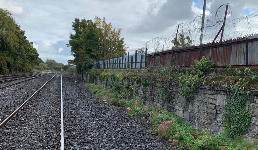
Tables
Table 1-1 Route Breakdown                                                                        16

Table 4-1 Details of the constraints to install the four tracks                                  36

Table 5-1 Main Options Summary for corridor area around Inchicore Works.                         46

Table 5-2 Options summary                                                                        52

Table 6-1 Comparison Criteria                                                                    65

Table 6-2 Sifting Process for the selection of the Preferred Option for the project (Inchicore
Works area)                                                                                      66

Table 6-3 Summary of Sifting Process Results (Inchicore Works area)                              68

Table 6-4 MCA Summary (Corridor Area around Inchicore Works)                                     70

Table 6-5 Preliminary Assessment (Sifting) Findings at Khyber Pass Footbridge area               71

Table 6-6 Summary of Sift Process Results (Khyber Pass Footbridge area)                          72

DP-04-23-ENG-DM-TTA-56610
                                                      Page 4 of 98
Figures
Figure 1-1 Schematic of Overall DART+ Programme                                             14

Figure 1-2 DART+ South West Route Map                                                       15

Figure 2-1 Existing track layout at area around Inchicore Works                             19

Figure 2-2 General view of the study area around Inchicore Works.                           20

Figure 2-3 Extent of Area associated with Khyber Pass Reconstruction (white dotted outline) 21

Figure 2-4 Main Challenges to the widening of the railway corridor.                         21

Figure 2-5 Track layout in the vicinity of Inchicore Works.                                 23

Figure 2-6 Connection of Down Main track (centre) with the Inchicore Long Siding (right).   23

Figure 2-7 Existing trap points at the East of Long Siding (Points 702).                    24

Figure 2-8 Track layout in the vicinity of Khyber Pass Footbridge (OBC5)                    24

Figure 2-9 Inchicore Works; technical buildings and offices.                                25

Figure 2-10 Khyber Pass Footbridge (OBC5), west elevation                                   26

Figure 2-11 North boundary wall                                                             26

Figure 2-12 - Existing Utilities Kylemore to Sarsfield                                      30

Figure 3-1 Typical OHLE arrangement in four track open route – Facing East                  32

Figure 3-2 Typical anchor structure                                                         33

Figure 3-3 Typical arrangement on approach to a low bridge                                  33

Figure 4-1 Existing pathway not sufficiently wide to provide ambulant disabled access       35

Figure 4-2 Land to the west (LHS) and east (RHS) of the existing north access steps         35

Figure 4-3 Minimum distance of 1.8m from property wall on the north to nearest track.       36

Figure 4-4 Old Signal box, located at 1. 6m to the nearest rail.                            37

Figure 4-5 Medical Centre and Apartment buildings in the north.                             37

Figure 4-6 Industrial properties West of Inchicore Works.                                   38

Figure 4-7 Location of the maintenance shed, the attached building and the sidings.         39

Figure 4-8 Attachment to the maintenance shed                                               39

Figure 4-9 View of the Turret.                                                              40

Figure 4-10 Track and Signal building. Three Tracks at this section.                        41

Figure 4-11 HQ Signalling building.                                                         41

Figure 4-12 St George Villas, attenuation Facilities and UBC4.                              42

Figure 4-13 Minimum distance from property boundary to the nearest track.                   42

Figure 4-14 Boundary wall constraints at Khyber Pass Footbridge (OBC5)                      44

Figure 5-1 Option 3. Design at the West end of the area around Inchicore Works.             47

Figure 5-2 West end of the area around Inchicore Works.                                     48

Figure 5-3 West Entrance to Inchicore Works and GSM-R communication tower.                  49
DP-04-23-ENG-DM-TTA-56610
                                              Page 5 of 98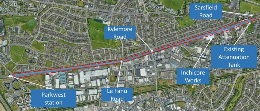
Figure 5-4 Building attached to the maintenance shed to be removed in all the Options.          49

Figure 5-5 Existing Siding Proposed Realignment.                                                50

Figure 5-6 Relative position between the tracks and the Turret in Option 4.                     51

Figure 5-7 Option 4, impact on Irish Rail facilities and St George's Villas in the South.       52

Figure 5-8 Option 1 - Bridge retained with derailment blocks installed to front of supports –
Facing East                                                                                     53

Figure 5-9 Option 2 - Alternative pedestrian and cycle route                                    53

Figure 5-10 Option 3 - Bridge replacement, west elevation – Facing East                         54

Figure 5-11 Option 3 - Bridge replacement, cross section                                        54

Figure 5-12 Replacement walls locations                                                         56

Figure 5-13 Attenuation tank boundary wall and fence.                                           57

Figure 5-14 Extension of railway corridor where new track drainage may be installed             57

Figure 5-15 Proposed attenuation tank and outfall for Network 1.                                58

Figure 5-16 Proposed attenuation tank and outfall point for Network 2.                          59

Figure 5-17 Ancillary bay affected by trackwork.                                                59

Figure 5-18 Demolition of the Accilliary Bay and proposed location for new administration
building.                                                                                       60

Figure 5-19 Inchicore Proposed Construction Compound Location                                   61

Figure 5-20 Khyber Pass Proposed Construction Compound Location                                 62

Figure 6-1 Inchicore Proposed Construction Compound Location                                    73

Figure 6-2 Khyber Pass Footbridge Proposed Construction Compound Location                       74

Figure 6-3 Construction Compound Location                                                       74

Figure 7-1 Khyber Pass Footbridge (OBC5) General Arrangement                                    77

Figure 7-2 Khyber Pass Footbridge (OBC5) Bridge Deck and Stairs Longitudinal Section –
Facing East                                                                                     78

Figure 7-3 Retaining Walls & Ground Anchors – Facing West                                       78

Figure 7-4 Example of a Secant Wall                                                             79

Figure 7-5 Examples of Retaining Walls                                                          79

Figure 7-6 Kylemore Road Bridge (OBC5A) to Sarsfield Road Bridge (UBC4) – Track Plan
Layout                                                                                          80

Figure 7-7 Cross Section looking West at CH 11+000 showing retained Turret at Inchicore Works
– Facing West                                                                             81

Figure 7-8 Signalling Scheme Plan (Kylemore – Sarsfield Road)                                   82

Figure 7-9 Signalling and LV Infrastructure (Kylemore – Sarsfield Road) (1 of 3)                83

Figure 7-10 Signalling and LV Infrastructure (Kylemore – Sarsfield Road) (2 of 3)               83

Figure 7-11 Signalling and LV Infrastructure (Kylemore – Sarsfield Road) (3 of 3)               84

DP-04-23-ENG-DM-TTA-56610
                                              Page 6 of 98
Figure 7-12 Typical Signal Post                                                         84

Figure 7-13 Typical Object Controller Cabinet (OBJ)                                     85

Figure 7-14 Typical Location Cases                                                      85

Figure 7-15 Containment walkway                                                         86

Figure 7-16 Typical OHLE TTC arrangement in four-track open route – Facing West         87

Figure 7-17 Example of a free running OHLE system at Kyber Pass Bridge (OBC5) – Facing East
                                                                                        87

Figure 7-18 Kylemore Substation Preferred Location                                      87

Figure 8-1 Proposed construction compound Locations – Inchicore Materials Processing Center
                                                                                         92

Figure 8-2 Proposed construction compound Locations – Khyber Pass Footbridge            93

Figure 8-3 Proposed construction compound Locations – Khyber Pass Footbridge            93

Figure 8-4 Alternative Access roads                                                     94

DP-04-23-ENG-DM-TTA-56610
                                          Page 7 of 98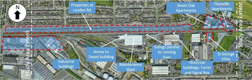
Glossary of Terms
 Reference        Description

 ABP              An Bord Pleanála

 ACA              Architectural Conservation Area

 AOD              Above Ordnance Datum

 APIS             Authorisation for Placing in Service

 ASA              Application for Safety Approval

 AsBo             Assessment Body

 ASPSC            Application Specific Project Safety Case

 ATP              Automatic Train Protection

 CAF              Common Appraisal Framework

 Cantilever       OHLE structure comprising horizontal or near horizontal members supporting the catenary projecting from a
                  single mast on one side of the track.

 Catenary         The longitudinal wire that supports the contact wire.

 CAWS             Continuous Automatic Warning System

 CBI              Computer-Based Interlocking

 CCE              Chief Civils Engineers Department of IE

 CCRP             City Centre Re-signalling Project

 CCTV             Closed Circuit Television

 CDP              County Development Plan

 CIÉ              Córas Iompair Éireann

 Contact wire     Carriers the electricity which is supplied to the train by its pantograph.

 CPO              Compulsory Purchase Order

 Cross overs      A set of railway parts at the crossing of several tracks which helps trains change tracks to other directions.

 CRR              Commission for Rail Regulation (formerly RSC – Railway Safety Commission)

 CSM RA           Common Safety Method for Risk Evaluation and Assessment

 CSS              Construction Support Site, Interchangeable with Construction Compound

 CTC              Central Traffic Control

 Cutting          A railway in cutting means the rail level is below the surrounding ground level.

DP-04-23-ENG-DM-TTA-56610
                                                    Page 8 of 98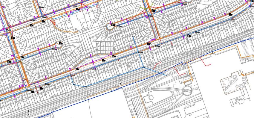
Reference         Description

 D&B               Design & Build (contractor)

 DART              Dublin Area Rapid Transit (IÉ’s Electrified Network)

 DART+             DART Expansion Programme

 DeBo              Designated Body

 DC                Direct Current, electrical current that flows in one direction, like that from a battery.

 DCC               Dublin City Council

 DRR               Design Review Report

 DSR               Design Statement Report

 EIA               Environmental Impact Assessment

 EIAR              Environmental Impact Assessment Report

 EIS               Environmental Impact Statement

 Electrification   Electrification is the term used in supplying electric power to the train fleet without the use of an on-board prime
                   mover or local fuel supply.

 EMC               Electromagnetic Compatibility

 EMU               Electric Multiple Unit (DART train)

 EN                European Engineering Standard

 EPA               Environmental Protection Agency

 EPO               Emerging Preferred Option

 ERTMS             European Rail Traffic Management System

 ESB               Electricity Supply Board

 Four-tracking     Four-tracking is a railway line consisting of four parallel tracks with two tracks used in each direction. Four track
                   railways can handle large amounts of traffic and are often used on busy routes.

 FRS               Functional Requirements Specification

 FSP               Final Supply Points

 GDA               Greater Dublin Area

 GI                Ground Investigation

 HAZID             Hazard Identification

 Horizontal        The horizontal distance between a bridge support and the nearest railway track is referred to as horizontal
 Clearance         clearance. Bridge supports include abutments (at the ends of the bridge) and piers (at intermediate locations).

 HV                High Voltage

DP-04-23-ENG-DM-TTA-56610
                                                     Page 9 of 98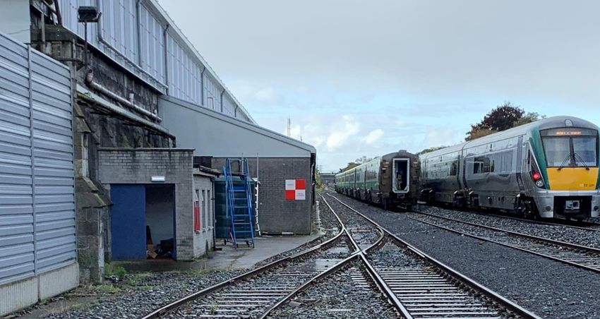
Reference           Description

 IA                  Independent Assessor

 IÉ
                     Iarnród Éireann

 IM                  Infrastructure Manager (IÉ)

 IMSAP               Infrastructure Manager Safety Approval Panel

 Insulators          Components that separate electricity live parts of the OHLE from other structural elements and the earth.
                     Traditionally ceramic, today they are often synthetic materials.

 KCC                 Kildare County Council

 Lateral Clearance   Clearances between trains and structures.

 LCA                 Landscape Character Area

 Mast                Trackside column, normally steel that supports the OHLE.

 MCA                 Multi-criteria Analysis

 MDC                 Multi-disciplinary Consultant

 MEP                 Mechanical electrical and plumbing

 MFD                 Major Feeding Diagram

 MMDC                Maynooth Multi-disciplinary Consultant

 MV                  Medium Voltage

 NDC                 National Biodiversity Data Centre

 NIAH                National Inventory of Architectural Heritage

 NoBo                Notified Body

 NTA                 National Transport Authority

 OHLE                Overhead Line Equipment

 Overbridge (OB)     A bridge that allows traffic to pass over a road, river, railway etc.

 P&C                 Points and Crossings

 Pantograph          The device on top of the train that collects electric current from the contact wire to power the train.

 PC                  Public Consultation

 Permanent Way       A term used to describe the track or railway corridor and includes all ancillary installations such as rails, sleepers,
                     ballast as well as lineside retaining walls, fencing and signage.

 POAP                Plan-On-A-Page, high-level emerging programme

 PPT                 Phoenix Park Tunnel

DP-04-23-ENG-DM-TTA-56610
                                                       Page 10 of 98
Reference Description
PRS Project Requirement Specification
PSCS Project Supervisor Construction Stage
PSDP Project Supervisor Design Process
PSP Primary Supply Points
QA/QC Quality Assurance/Quality Control
RAM Reliability, Availability, Maintainability
RC Reinforced Concrete
Re-signalling Re-signalling of train lines will regulate the sage movement of trains and increase the capacity of train services
along the route.
RMP Record of Monuments and Places
RO Railway Order
RPS Record of Protected Structures
RSC-G Railway Safety Commission Guideline
RU Railway Undertaking (IÉ)
SAM Safety Assurance Manager
SAP Safety Approval Panel
SDCC South Dublin County Council
SDZ Strategic Development Zone
SET Signalling, Electrical and Telecommunications
Sidings A siding is a short stretch of railway track used to store rolling stock or enable trains on the same line to pass
SMR Sites and Monuments Records
SMS IÉ Safety Management System
STC Single Track Cantilever
TII Transport Infrastructure Ireland
TMS Train Management System
TPH Trains per Hour
TPHPD Trains per Hour per Direction
TPS Train Protection System
DP-04-23-ENG-DM-TTA-56610
Page 11 of 98Reference Description
Track Alignment Refers to the direction and position given to the centre line of the railway track on the ground in the horizontal
and vertical planes. Horizontal alignment means the direction of the railway track in the plan including the straight
path and the curves it follows.
TSI Technical Specifications for Interoperability
TSS Train Service Specification
TTAJV TYPSA, TUC RAIL and ATKINS Design Joint Venture (also referred to as TTA)
TTC Two Track Cantilever
Underbridge (UB) A bridge that allows traffic to pass under a road, river, railway etc. The underneath of a bridge.
VDC Direct Current Voltage
Vertical Clearance For overbridges, an adequate vertical distance between railway tracks and the underside of the bridge deck
(soffit) must be provided in order to safely accommodate the rail vehicles and the OHLE. This distance is known
as vertical clearance and it is measured from the highest rail level.
WFD Water Framework Directive
DP-04-23-ENG-DM-TTA-56610
Page 12 of 981. Introduction
1.1. Purpose of Report
The purpose of this report is to provide technical input to the Option Selection Report to inform Public Consultation
no.2 (PC2). This report shows the options considered as part of the project development and why the preferred
option for PC2 was chosen.
This report provides the technical assessment of area around Inchicore Works and Khyber Pass Footbridge
(OBC5). This report presents the approach to option development, options assessment, and options selection.
This optioneering process incorporates assessment by the following Design Workstreams and specialist Project
Teams:
• Permanent Way
• Civils and Structures
• Signalling, Electrification and Telecommunications (SET) and Low Voltage Power
• Overhead Line Equipment (OHLE)
• Environment
• Highways
• Geotechnical
• Construction Compounds
The report provides:
• An area overview and a detailed description of the existing railway infrastructure and challenges.
• The Project Requirements for this area.
• The technical and environmental constraints, including the horizontal and vertical clearances at
structures.
• The options considered for this area.
• The option selection process leading to the identification of the Preferred Option, including the Sifting
process and the Multi-Criteria Analysis process.
• A summary of the feedback received from the first public consultation which was held in May/June 2021
• An update on the design development
• An overview of the proposed construction methodology and requirements in terms of construction
compounds.
DP-04-23-ENG-DM-TTA-56610
Page 13 of 981.2. DART+ Programme Overview
The DART+ Programme is a transformative railway investment programme that will modernise and improve the
existing rail services in the Greater Dublin Area. It will provide a sustainable, electrified, reliable and more frequent
rail service, improving capacity on rail corridors serving Dublin.
Figure 1-1 Schematic of Overall DART+ Programme
The current electrified DART network is 50km long, extending from Malahide / Howth to Bray / Greystones, and
the DART+ Programme seeks to increase the network to 150km. The DART+ Programme is required to facilitate
increased train capacity to meet current and future demands which will be achieved through a modernisation of
the existing railway corridors. This modernisation includes the electrification, re-signalling and certain
interventions to remove constraints across the four main rail corridors within the Greater Dublin Area, as per
below:
• DART+ South West (this Project) – circa 16km between Hazelhatch & Celbridge Station andHeuston
Station and also circa 4km between Heuston Station andGlasnevin Junction, via the Phoenix Park Tunnel
Branch Line.
• DART+ West – circa 40km from Maynooth & M3 Parkway Stations to the City Centre.
• DART+ Coastal North – circa 50km from Drogheda to the City Centre.
• DART+ Coastal South – circa 30km from Greystones to the City Centre.
The DART+ Programme also includes the purchase of new electrified fleet to serve new and existing routes.
DP-04-23-ENG-DM-TTA-56610
Page 14 of 98The DART+ Programme is a key element to the national public transportation network, as it will provide a high-
capacity transit system for the Greater Dublin Area and better connectivity to outer regional cities and towns. This
will benefit all public transport users.
The Programme has also been prioritised as part of Project Ireland 2040 and the National Development Plan
2021-2030 as it is integral to the provision of an integrated, high-quality public transport system.
Delivery of the Programme will also promote transport migration away from the private car and to public transport.
This transition will be achieved through a more frequent and accessible electrified service, which will result in
reduced road congestion, especially during peak commuter periods.
Ultimately, the DART+ Programme will provide enhanced, greener public transport to communities along the
DART+ Programme routes, delivering economic and societal benefits for current and future generations.
1.3. DART+ South West Project
The DART+ South West Project will deliver an electrified network, with increased passenger capacity and
enhanced train service between Hazelhatch & Celbridge Station to Heuston Station (circa 16km) on the Cork
Mainline, and Heuston Station to Glasnevin via Phoenix Park Tunnel Branch Line (circa 4km).
DART+ South West Project will complete four-tracking between Park West & Cherry Orchard Station and
Heuston Station and will also re-signal and electrify the route. The completion of the four-tracking will remove a
significant existing constraint on the line, which is currently limiting the number of train services that can operate
on this route. DART+ South West will also deliver track improvements along the Phoenix Park Tunnel Branch
Line, which will allow a greater number of trains to access the city centre.
Upon completion of the electrificationof the DART+ South West route, new DART trains will be used on this
railway corridor, similar to those currently operating on the Malahide / Howth to Bray / Greystones Line.
Figure 1-2 DART+ South West Route Map
1.4. Capacity Increase Delivered by DART+ South West
DART+ South West will improve performance and increase train and passenger capacity on the route between
Hazelhatch & Celbridge Station to Heuston Station and through the Phoenix Park Tunnel Branch Line to the City
Centre, covering a distance of circa 20km. It will significantly increase train capacity from the current 12 trains
per hour per direction to 23 trains per hour per direction (i.e. maintain the existing 12 services, with an additional
11 train services provided by DART+ South West). This will increase passenger capacity from the current peak
capacity of approximately 5,000 passengers per hour per direction to approximately 20,000 passengers per hour
DP-04-23-ENG-DM-TTA-56610
Page 15 of 98per direction. Upon completion of the DART+ South West Project, train services will be increased according to
passenger demand.
1.5. Key infrastructure elements of DART+ South West Project
The key elements of DART+ South West include:
• Completion of four-tracking from Park West & Cherry Orchard Station to Heuston Station, extending the
works completed on the route in 2009.
• Electrification of the line from Hazelhatch & Celbridge Station to Heuston Station and also from Heuston
Station to Glasnevin Junction, via the Phoenix Park Tunnel Branch Line, where it will link with proposed
DART+ West.
• Undertaking improvements / interventions of bridges to achieve vertical and horizontal clearances.
• Remove rail constraints along the Phoenix Park Tunnel Branch Line.
• Delivery of a new Heuston West Station.
The ‘Preferred Option’ will be compatible with the future stations at Kylemore and Cabra, although the
construction of these stations is not part of the DART+ South West Project.
1.6. Route Description
The existing rail corridor extends from Heuston Station to Hazelhatch Station, the route also extends through the
Phoenix Park Tunnel to Glasnevin. The area descriptions and extents are set out in Table 1-1 and Figure 1-2.
Table 1-1 Route Breakdown
Area Name Sub-area Description Extents Main Features
Hazelhatch &
Celbridge Station
West side of Hazelhatch & Adamstown Station
Hazelhatch to Park Area from Hazelhatch to Celbridge Station to 50m to
West Park West (Volume 3A) west of Cherry Orchard Clondalkin/Fonthill
Footbridge (OBC8B) Station
Park West & Cherry
Orchard Station
West of Cherry Orchard Cherry Orchard
Area from Park West to Footbridge (OBC8B) to the Footbridge (OBC8B)
Le Fanu (Volume 3B) East of the proposed Le Le Fanu Road
Fanu Road Bridge (OBC7) Bridge (OBC7)
Park West to
Heuston Station East of the proposed Le
Fanu Road Bridge (OBC7) to
Area from Le Fanu to Kylemore Road
the East of IE700B (i.e. the
Kylemore (Volume 3C) Bridge (OBC5A)
points for the Inchicore
headshunt turnout)
DP-04-23-ENG-DM-TTA-56610
Page 16 of 98Area Name Sub-area Description Extents Main Features
East of IE700B (i.e. the Inchicore Works
points for the Inchicore Depot
Area from Kylemore to
headshunt turnout to the
Sarsfield (Volume 3D) Khyber Pass
west of Sarsfield Road
Bridge (UBC4) Footbridge (OBC5)
West of Sarsfield Road
Area from Sarsfield to Bridge (UBC4) to the West of Sarsfield Road
Memorial (Volume 3E) Memorial Road Bridge Bridge (UBC4)
(OBC3)
Memorial Road (Volume Area around Memorial Road Memorial Road
3F) Bridge Bridge (OBC3)
South Circular Road
Junction
Area from Memorial East of Memorial Road
Road to South Circular Bridge (OBC3) to East of St South Circular Road
Road Junction (Volume John’s Road Bridge Bridge (OBC1)
3G) (OBC0A)
St Johns Road
Bridge (OBC0A)
Area around Heuston Area at the South side of the Heuston Station
Station and Yard Heuston Station Yard (non- Sidings around
(Volume 3H) DART+ tracks) Heuston Station
Area to the West of Heuston
Heuston West New Heuston West Heuston West
Station, adjacent to Liffey
Station Station (Volume 3I) Station
Bridge (UBO1)
Liffey Bridge
East of St John’s Road (UBO1).
St John’s Road East of St John’s Road
Bridge (OBC0A)
Bridge Bridge (OBC0A) Conyngham Road
(Islandbridge) to North
(Islandbridge) to (Islandbridge) to North of Bridge (OBO2)
of Phoenix Park Tunnel
Glasnevin Junction Phoenix Park Tunnel
(Volume 3J) Phoenix Park
Tunnel
McKee Barracks
Bridge (OBO3)
Blackhorse Avenue
Bridge (OBO4)
Old Cabra Road
North of the Phoenix Bridge (OBO5)
St John’s Road North of Phoenix Park
Park Tunnel to
Bridge to Glasnevin Tunnel to South of Glasnevin Cabra Road Bridge
Glasnevin Junction
Junction Junction (OBO6)
(Volume 3K)
Fassaugh Avenue
Bridge (OBO7)
Royal Canal and
LUAS Twin Arches
(OBO8)
DP-04-23-ENG-DM-TTA-56610
Page 17 of 98Area Name Sub-area Description Extents Main Features
Maynooth Line Twin
Arch (OBO9)
Glasnevin Cemetery
Road Bridge
(OBO10)
1.7. Stakeholder Feedback
A large volume of stakeholder submissions were received during the six week public consultation period, which
ran from 12th May 2021 to 23rd June 2021, an additional week was provided, extending the consultation period
until 30th June 2021. All submissions received either via email, post, telephone, or through the online feedback
form, were analysed and recorded by the project team on a dedicated consultation database. Each individual
submission was analysed to identify the themes that were raised by the respondent and each submission was
classified according to the themes raised. All feedback provided, was then anonymised before being analysed
under each of the themes. In addition, further engagement with relevant local authorities and prescribed
stakeholders has been ongoing. Engagement with potentially affected landowners has also taken place since the
commencement of PC1.
All submissions received as part of the first round of public consultation have fed into the design process and the
selection of the Preferred Option. The project team has analysed the submissions and considered all relevant
information in re-evaluation and further development of design options leading to the selection of the Preferred
Option.
Stakeholders expressed concern regarding air pollution. Stakeholders expressed concern that the works and
increased train activity will only worsen the situation.
Submissions cited that infrastructure was already in place for a station in Inchicore and to not include a station
would be a massive ‘over sight’. Stakeholders expressed concerns on how the project will impact traffic around
Inchicore and were worried that the project may exacerbate the existing traffic impact on Sarsfield Road.
With regard to traffic impact, a number of submissions had concerns around the Inchicore Area.
Submissions were mixed with regard to Khyber Pass footbridge. Some respondents felt it should be opened to
the public and included improved access for wheelchair and cycle access as they believed it could provide good
connectivity to the Red Line LUAS and other services on Tyrconnell Road. While other respondent submissions
expressed concern at it being used for open public use and the potential for antisocial behavior.
Further details of the Stakeholder Feedback are captured in the Public Consultation No. 1: Findings Report,
Volume 4.
Similarly, all feedback received on the Preferred Option at Public Consultation No.2 will feed into the development
of the preliminary design, Railway Order and Environmental Impact Assessment Report (EIAR).
A high-level summary review of the above is also outlined in Section 7.2 Review of Stakeholder Feedback of
the report.
DP-04-23-ENG-DM-TTA-56610
Page 18 of 982. Existing Situation
2.1. Overview
Currently, the four-track section on the Cork Mainline terminates immediately east of Park West Station where
the lines converge into two running lines which continue from Park West Station to Kylemore Road Bridge
(OBC5A). East of Kylemore Road Bridge (OBC5A) there is an additional siding track to the south of the mainline
that provides the entrances and exits to and from Inchicore Works. Adjacent to Inchicore are two siding tracks,
the Long Siding and the Short Siding, which account for a maximum width of up to four tracks running parallel
through part of the Inchicore area. Where the sidings end to the east of the Inchicore facility the third line to the
south of the mainline becomes the third running line as it heads east. The project requirement is to continue the
four tracks from Park West Station to Heuston Station. The existing track layout is shown in Figure 2-1.
Figure 2-1 Existing track layout at area around Inchicore Works
This area starts at Points 700B, located on the east side of Kylemore Road Bridge (OBC5A). Here, the track is
in a cutting and the two main lines run parallel to the Inchicore Works sidings. On the north side of the corridor
the back gardens of the houses at Landen Road limit the rail corridor, and, on the south side, Inchicore Works
can be found.
The Maintenance Shed in Inchicore Works is located 900m east of Kylemore Road Bridge (OBC5A). Here, the
railway is at grade, and the tracks run between the Old Signal Box and the Turret (a Heritage building). The Track
and Signal building and Khyber Pass Footbridge (OBC5) are located immediately to the east of Inchicore Works.
On the east side of the Works the tracks are on an embankment. The Seven Oaks apartment building and
Floraville apartment building are located to the north side at a lower level than the track. On the south side, St
George´s Villas and existing drainage attenuation facilities can be found. The demarcation between this area,
around Inchicore Works, and the area around Sarsfield Road Bridge (UBC4) is the east side of Sarsfield Road
Bridge (UBC4). The general view of the area is demonstrated in Figure 2-2.
The project scope in this area is to increase the number of running lines up to a four-tracking section and electrify
the two tracks at the North (Slow tracks) for the DART services. The existing depot functionality must be
maintained. The depot is for the maintenance and refurbishment of railway activities.
DP-04-23-ENG-DM-TTA-56610
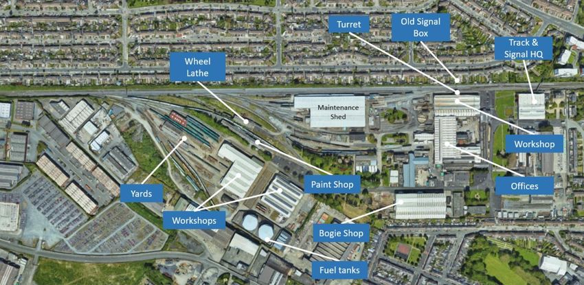
Page 19 of 98Figure 2-2 General view of the study area around Inchicore Works.
Inchicore Works is the main feature that is found in this area. The depot contains several facilities for the
maintenance of the intercity rolling stock, for infrastructure maintenance and other buildings that Irish Rail
employs as offices and training rooms.
This report also covers the localized area at the existing Khyber Pass Footbridge (OBC5). This is a private
footbridge for IÉ employees to access the depot from the north of the railway. The Permanent Way in this area
currently consists of 3 No. tracks. The rail is at grade and approximately the same level as the surrounding
ground. There is a masonry boundary wall along the north side of the rail corridor at this location.
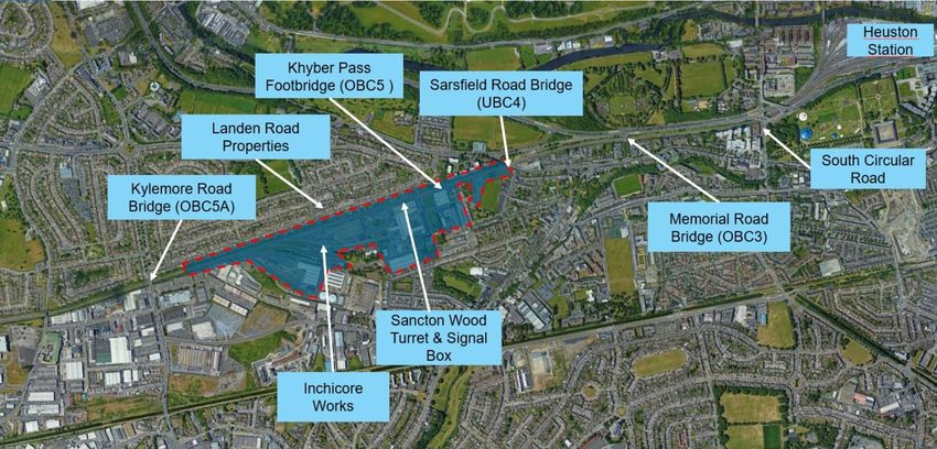
The major infrastructure features of the area are illustrated in Figure 2-3.
DP-04-23-ENG-DM-TTA-56610
Page 20 of 98Figure 2-3 Extent of Area associated with Khyber Pass Reconstruction (white dotted outline)
2.2. Challenges
The main challenge to provide the two additional running lines while maintaining the depot functionality is to
increase the area of the existing rail corridor.
There are two possibilities: widen the corridor to the North or to the South of the existing tracks. Each alternative
would have to consider the elements along the area. In Figure 2-4, the main elements that constrain the track
alignment are shown.
Figure 2-4 Main Challenges to the widening of the railway corridor.
DP-04-23-ENG-DM-TTA-56610
Page 21 of 98The increased railway corridor area would be used for the installation of four new running lines. In the new
configuration, the tracks will be paired by speed, with the Slow tracks for the slower services (DART services that
would stop at each intermediate station) and the Fast tracks for the faster services (Intercity trains or freight trains
that would not stop in most of the intermediate stations). This configuration is set to maximise rail capacity. The
name of the tracks in the new configuration will be, from North to south, Up Slow, Down Slow, Up Fast and Down
Fast. The resulting track configuration, with a continuous four-track section from Hazelhatch through to Heuston,
will remove the existing bottleneck from Park West station to Heuston caused by the existing two or three track
sections.
The Slow tracks, the tracks on the North, will be electrified and used by the DART services. The Intercity service
trains will use the Fast lines that will not be electrified. The functionality of the Inchicore depot must be maintained
to ensure continued operational railway function.
The new corridor area would have to consider the installation of the OHLE equipment for the electrification of the
Slow lines.
Suitable and safe access for the rail maintenance teams is also important. The railway corridor must include the
access strategy in the area.
The challenge in the Khyber Pass Footbridge (OBC5) area is the constraint that is posed by the existing Khyber
Pass Footbridge (OBC5) structure. It has insufficient horizontal clearance to facilitate 4 No. tracks to IÉ design
standards without a structural intervention.
2.3. Permanent Way and Tracks
The area around Inchicore Works commences at the connection of the Down Main line to the Long Siding at
Points 700B. From there the rail corridor comprises three tracks: two running lines (Up Main and Down Main)
and a siding (Long Siding). A fourth siding, the Short Siding, parallel to the mainline extends past the Maintenance
Shed of Inchicore Works. The Long Siding is connected to the various tracks leading into the depot, whilst the
Short Siding is used for train stabling. The Long Siding ends at trap points 702 to the west of Inchicore depot,
and from there the track is designated as the Relief Line. The Relief Line completes the three tracks that run east
to Heuston Station. The track layout is shown in Figure 2-5.
There is an existing speed limit in front of the maintenance shed, with line speed increasing from 40mph (60km/h)
to 60mph and 70mph (100km/h and 110 km/h) as we move east towards Heuston along the Up Main and Down
Main tracks respectively. The speed restriction is related to the constraint that is imposed by the Old Signal Cabin
that prevents the track from having an optimal alignment in this area.
DP-04-23-ENG-DM-TTA-56610
Page 22 of 98Figure 2-5 Track layout in the vicinity of Inchicore Works.
From Park West the track gradient falls towards Heuston at an approximate slope of 1%. Similarly, this is the
gradient of the two sidings parallel to the running line (Long and Short sidings).
The connection between the Down Main and the Long siding on the west side is protected by trap points, with a
fixed buffer stop as an arresting device (refer to Figure 2-6). The level difference between the siding and the
main tracks can be observed in the picture.
Figure 2-6 Connection of Down Main track (centre) with the Inchicore Long Siding (right).
The sidings are at a lower level than the running lines. The level difference varies from around 400mm at the
west connection to zero at the east end and a proprietary retaining system is used to support the level difference.
To the east, the Inchicore siding ends in trap points without any element to arrest a train overrun as shown in
Figure 2-7. After this, the Long Siding becomes the Relief Line.
DP-04-23-ENG-DM-TTA-56610
Page 23 of 98Figure 2-7 Existing trap points at the East of Long Siding (Points 702).
The trackform is comprised of a ballasted track with 54E1 rail and concrete sleepers. The P&C layouts are
normally on timber bearers (some of the units are on concrete bearers), protected from the thermal forces by
adjustment or breather switches.
Currently at Khyber Pass Footbridge (OBC5) there are 3 no. tracks beneath the bridge, they are named from
north to south: Up Main, Down Main and Relief Line. The connection to the Inchicore Works depot, where the
Relief Line becomes the Long Siding is 180m to the west. At the bridge there are several crossovers to provide
access to the depots from the three main lines. See Figure 2-8 for a track layout in the vicinity of Khyber Pass
Footbridge.
Figure 2-8 Track layout in the vicinity of Khyber Pass Footbridge (OBC5)
DP-04-23-ENG-DM-TTA-56610
Page 24 of 982.4. Other railway Facilities
Inchicore Works contains several facilities for the maintenance of rolling stock (intercity trains), the maintenance
of the track infrastructure and offices for IÉ. In Figure 2-9, the location of some of the main buildings is
represented. A Warehouse for the maintenance of rolling stock, offices, a training centre and fuel tanks is found
within the area.
Figure 2-9 Inchicore Works; technical buildings and offices.
The access to the depot is through the Long siding where all the depot tracks are connected to
Refer to Section 4.1 Environment the description of the level of protection of the buildings in this area.
2.5. Structures
The Khyber Pass Footbridge (OBC5) is an existing pedestrian bridge at Inchicore Works. The steel structure was
manufactured and installed by Iarnród Éireann in the early ’00s. The bridge crosses the existing tracks at a high
skew.
The single-span structure is supported on steel abutment supports and shallow foundations. The existing north
and south abutments have horizontal clearances greater than 4.5m (a minimum distance for which abutment
need not be designed for railway impact loading). The north abutment is positioned outside the north CIE
boundary wall (i.e. to the North of the boundary wall). The south abutment is located on the north side of the
Iarnród Éireann Infrastructure building.
The internal width of the structure is 1.1m. A stairway on the north and south sides of the bridge facilitates access
to deck level for the users. The edge of stairways incorporates a bicycle ledge that allows users to more easily
manoeuvre bicycles to and from deck level. The bridge deck is fully enclosed. The height of the enclosed deck
is 2.7m.
Access to the R833 road on the north side is secured by means of a keypad locked steel access gate. The bridge
is exclusively for use by Iarnród Éireann staff and does not form part of a public footway. See Figures 2-10 and
2-11.
DP-04-23-ENG-DM-TTA-56610
Page 25 of 98Figure 2-10 Khyber Pass Footbridge (OBC5), west elevation
Figure 2-11 North boundary wall
2.6. Ground Conditions
The western extents of the Inchicore Works area are located within a steep cutting on both sides that are partially
covered by vegetation.
The northern cutting appears to gradually decrease in height in an easterly direction. A retaining wall covered by
vegetation exists along the northern boundary of the railway for the entire study area providing separation
between the railway and the residential properties. A retaining wall sits behind the cutting slope on the southern
DP-04-23-ENG-DM-TTA-56610
Page 26 of 98boundary between Kylemore and Inchicore Works and terminates at the sidings where the railway becomes at
grade. Further to the east, the south of the railway is bound by the sidings, maintenance sheds, car park and
other buildings owned by Iarnród Éireann at the Inchicore Railway Works.
Close to the Khyber Pass Footbridge (OBC5), the railway transitions on both sides form a minor cutting to an at-
grade section, then onto an embankment section on the approach to Sarsfield Road Bridge (UBC4) - with
boundary walls on either side of the tracks.
Industrial units and the Inchicore Works generally form the southern boundary of the railway, and residential
properties form the entire northern boundary. Further, towards the east, apartment complexes are located north
of the railway line between the Khyber Pass Footbridge (OBC5) and Sarsfield Road Bridge (UBC4). Between the
Inchicore Railway Works and Sarsfield Road Bridge (UBC4), there are residential properties, vacant land covered
by grass and hardstanding, and an existing attenuation tank.
A review of the available geological maps suggests that the site is underlain entirely by till overlying bedrock. The
bedrock is described as limestone and shale.
A large amount of historical ground investigation is available within this area and has been summarised below.
Historical boreholes in the western extents of the site undertaken at road level close to Kylemore Road Bridge
(OBC5A) indicate the ground conditions to comprise clay underlain by limestone bedrock at 35.69m AOD. No
groundwater conditions were recorded.
In the centre of the site adjacent to the Inchicore Railway Works, the ground conditions typically consisted of
made ground underlain by soft to stiff clay and limestone bedrock. Historical boreholes completed west of the
Track and Signal Building encountered a thin layer of topsoil over the made ground to a depth of 1.40m bgl
(28.24m AOD). Drillers described the made ground as slag and stony clay. The made ground was underlain by
very soft to soft clay. Below the soft clay, stiff black clay was encountered that became very stiff with depth. The
borehole was terminated at 9.50m bgl (2014m AOD). The hole would be continued using the rotary techniques
in BHRC02 with bedrock encountered at 9.50m bgl (20.16m AOD) and was described as very strong limestone
and moderately strong mudstone and shale. Water strikes (recorded as seepage) was encountered during drilling
at 0.70m bgl and 5.30m bgl.
In the east, adjacent to Sarsfield Road Bridge (UBC4), historical boreholes report the ground conditions to
comprise made ground, underlain by a firm to stiff clay and gravel with limestone bedrock encountered at depths
ranging from 9.54m AOD and 12.73m AOD. No groundwater conditions were recorded.
Topographically the ground slopes gently towards the River Liffey east to west and the railway is at grade at
Khyber Pass Footbridge (OBC5).
The general superficial geology in the Khyber Pass Footbridge (OBC5) area is anticipated to comprise till
overlying bedrock (limestone and shale). A previous ground investigation completed 70m west of Khyber Pass
Footbridge (OBC5) recorded a thin layer of topsoil overlying made ground to depth of 1.40m below ground level
(bgl) (28.24m AOD). This was described as slag and stony clay. The made ground was underlain by very soft to
soft clay becoming stiff to very stiff with depth. The borehole was terminated at 9.50m bgl (20.14m AOD). Water
strikes recorded as seepage during drilling were noted at 0.70m bgl and 5.30m bgl.
The borehole was re-drilled from ground level using rotary coring techniques. The ground conditions recorded
were clayey gravel and gravelly clay between ground level and 8.50m bgl (21.14m AOD). There was no recovery
of this material. Firm clay was recorded from 8.50m bgl (21.14m AOD) overlying a thin layer of limestone gravel.
Rock comprising strong to very strong limestone and moderately weak mudstone and shale was encountered at
10.50m bgl (19.14m AOD).
DP-04-23-ENG-DM-TTA-56610
Page 27 of 98It is not envisaged that the development of options in this area will be governed by existing ground conditions as
the ground conditions noted will facilitate all likely options. Nevertheless a Ground Investigation is currently
ongoing to verify the ground conditions encountered in the historical investigations.
2.7. Environment
There is a significant residential development in close proximity to the north of the rail corridor at Landen Road,
in many cases within 50m of the existing rail centreline. There are also a number of residential apartment blocks
located to the north as the corridor approaches Sarsfield Road. There are also residential dwellings to the south
associated with Inchicore Road, Inchicore Parade (including St. Georges Villas) and St. Patrick’s Terrace.
Community facilities in this area include Markievicz Park, which is north of the Inchicore Works.
To the south, the lands are predominantly associated with the Inchicore Works and the functional railway sidings
for the cleaning and maintenance of the carriages. There is also significant built and industrial heritage value
associated with the Inchicore Works with a number of the buildings and features in the works listed on the National
Inventory of Architectural Heritage (NIAH), as well as the Record of Protected Structures (RPS).
Key features include a signal box to the North of the rail line (Regional Rating Reg No. 50080417) and a turret
associated with a locomotive shed to the south of the line (Regional Rating Reg. No. 50080418). There are also
two offices, several workshops, a warehouse, a turntable and a water pump also listed as NIAH.
The entire circuit boundary wall of the Inchicore Works is afforded statutory protection under the Dublin City
Development Plan [RPS Ref:8744, which reads ‘CIE Railway Estate: boundary wall dating from the 1850s
(including 20th-century reconstructions but excluding modern additions)’. In addition, specific sections of the
boundary wall of the Inchicore Works are also protected under RPS Ref:3300, RPS Ref:3992 and RPS Ref:7476.
The former Dispensary & Reading Rooms & Dining Hall, now Inchicore Sports & Social Club, within the estate
are also identified on the RPS.
The boundary circuit has been surveyed by the National Inventory of Architectural Heritage (NIAH) who have
assigned these a ‘Regional’ rating (NIAH Ref: 50080055).
The general works area is considered to have industrial heritage value associated with the historic rail line.
Biodiversity constraints to highlight within this area are noted as invasive alien species and bat roost potential,
which were identified previously.
2.8. Utilities
As there are no public roads directly impacted within this area, existing utilities networks are primarily limited to
trackside items and underground services crossing under the railway. Service providers with network assets in
this area include the following:
• ESB Networks
• Gas Networks Ireland
• Dublin City Council Road Drainage (Storm Water Sewers)
• Dublin City Council / Irish Water (Foul Water Sewers)
• Private water supply pipe (Irish Rail owned)
Data in the form of utility service records have been gathered from all providers in the area. The majority of
services are present at the track level, most of which are crossing the railway corridor below the tracks. Where
track lowering is proposed, consideration of the impacts on these services will be necessary.
There are a number of combined sewers and stormwater sewers crossing the tracks. In general, these services
provide linkage to public sewers located along Landon Road to the north. The Creosote Stream is located to the
DP-04-23-ENG-DM-TTA-56610
Page 28 of 98eastern extent of the study area. It flows in a general west-to-east direction before crossing under the railway
and Sarsfield Road at Sarsfield Road Bridge (UBC4) in a culvert. This culvert is located at a significant depth
compared to the railway surface level.
At the Khyber Pass Footbridge (OBC5) the only services that cross beneath are IÉ owned services that run
along the rail corridor. There are no other services that are above, below or in close proximity to the bridge.
;…….
DP-04-23-ENG-DM-TTA-56610
Page 29 of 98Figure 2-12 - Existing Utilities Kylemore to Sarsfield
2.9. Drainage
There are no known track drainage elements present in the area where the four tracking is to be implemented.
The only drainage asset that is identified in the area is within Inchicore Works. Inchicore Works has its own
drainage systems, with an outfall into the existing culvert under Sarsfield Road where the existing attenuation
tank, located north of the CIE Sports Ground, is thought to discharge. This existing attenuation tank holds the
runoff volumes drained from the Inchicore Works Depot.
DP-04-23-ENG-DM-TTA-56610
Page 30 of 983. Project Requirements
3.1. Area-Specific Requirements
In addition to the general feasibility requirements of constructability, general fitness for intervention and safety,
the specific requirements for this area are:
• Four tracking Park West to Heuston.
• Electrification of DART+ track with associated electrical substations
• Electrical clearance to structures
• Keep current functionality of railway (including Inchicore Works).
• Keep current functionality of footbridge (Khyber Pass)
• Replacement bridge options to be ambulant disabled accessible and incorporate a bicycle ledge
• Keep current functionality of existing roads and services/utilities (electricity, gas, water, etc)
• Track alignment and drainage requirements (in accordance with their respective standards).
3.2. Systems Infrastructure and Integration
In addition to the track and civil infrastructure modifications relating to them DART+ South West Project, there is
a requirement to provide Overhead Line Electrification Equipment (OHLE) signalling and telecoms infrastructure.
The electrification system will be similar in style to that currently used on the existing DART network and
integrated and compatible across the DART+ Programme. It is envisaged that a standardised approach to
electrification will be adopted, but those area-specific interventions will also be required.
The Low Voltage and Telecommunications networks required for Signalling will be ‘global systems’ and are
unlikely to vary significantly between or within the various areas. In order to achieve the necessary capacity
enhancements and performance required for the introduction of the new electric multiple unit (EMU) fleet, it will
be necessary to upgrade the existing signalling system as well as replacing some of the legacy signalling system.
This will include provision of Relocatable Equipment Buildings (REB) where required along the route in order to
accommodate signalling equipment and associated power supplies and backup.
Upgrades to the existing telecommunications infrastructure will be required to facilitate improvements to the radio-
based technologies used on the network and for signalling and communication with the existing and future
network control centres.
3.2.1. Electrification System
The OHLE system architecture is currently being developed. The Dart wide programme will adopt a 1500V Direct
Current (DC) OHLE system to provide electrical power to the network’s new electric train fleet.
It should be noted that all OHLE diagrams in this report are for visual information only. Construction details will
be determined during Detail Design, which will be developed at later stages of the project
The OHLE concept comprises a simple (2-wire) auto-tensioned system, supported on galvanised steel support
structures. See Figure 3-1 for a typical OHLE arrangement in a four track open route.
In the four track areas, Two Track Cantilevers (TTCs) will generally be placed on the north side of the line, to
support OHLE on the northern two tracks. The project aims to achieve a minimum contact wire height of 4.4m
DP-04-23-ENG-DM-TTA-56610
Page 31 of 98throughout to ensure compliance with the relevant design standards, localised special conditions may be
required.
Figure 3-1 Typical OHLE arrangement in four track open route – Facing East
For contact wire details under Khyber Pass Footbridge see Section 7.3.3. Signalling, Electrical and
Telecommunications.
Additional feeder cables will be supported from the masts at heights between 6.5m and 8m on each side of the
track. An earth wire will also be suspended from the masts.
Maximum tension length is 1600m. Overlaps will comprise three spans, with spring tensioners used throughout.
Midpoint Anchors (MPAs) will generally be of the tie-wire type, although the portal type may be needed in some
locations.
At intervals of up to 1500m the OHLE wires will be anchored at an arrangement known as an overlap, and a new
set of wires will take over. The anchors provide the mechanical tension that the wires need to perform reliably
and safely. In areas of crossovers and junctions, additional wiring will be provided for the extra tracks, and these
will also be provided with anchors. See Figure 3-2 for a typical anchor structure.
DP-04-23-ENG-DM-TTA-56610
Page 32 of 98Figure 3-2 Typical anchor structure
The OHLE configuration through the overbridges for each track have been assessed using a clearance
assessment tool derived from the System Wide Functional Requirement Specification (FRS) relating to Overhead
Line Equipment (OHLE) and a set of configurations agreed with Irish Rail Signalling and Electrification
Department through the Interface Coordination Document (ICD) process This includes level and graded free
running options, as well as level and graded options with elastic bridge arms fitted to the bridge. See Figure 3-3
for a typical arrangement on approach to a low bridge.
Figure 3-3 Typical arrangement on approach to a low bridge
3.3. Design Standards
The project design is governed by various technical and safety guidelines, which include European, National and
Iarnród Éireann internal standards and specifications.
Compliance with these standards will be ensured via internal and external technical and safety assurance
processes throughout the delivery and commission stages of the project.
DP-04-23-ENG-DM-TTA-56610
Page 33 of 984. Constraints
4.1. Environment
The key environmental constraints in this area relate to proximity to residential properties, heritage assets
associated with Inchicore Works and material assets associated with existing rail infrastructure. Further desk and
field survey work has been undertaken to inform the environmental constraints identified in Section 2.8 and the
feedback from PC1 has been reviewed. Together that information has improved the understanding of the
environmental constraints in the study area. Details of the further desk and field survey work and stakeholder
feedback from PC1 is outlined below.
Ecological field surveys of the route have been carried out to establish the baseline ecological conditions. Surveys
for mammals (badger, bats), amphibians, invasive alien species, birds and terrestrial and freshwater habitats
have been carried out to date. Bat dusk emergence and dawn re-entry surveys have been carried out to
characterise and identify bat roosting at the old signal box and the turret associated with a locomotive shed at
Inchicore Works.
In relation to Built Heritage, a comprehensive desktop assessment of built heritage assets within 50m either side
of the railway centreline has been undertaken by a Heritage Specialist. This assessment confirmed the
designated status of the features of heritage interest i.e. Protected Structure status and/or inclusion in the NIAH
record, and/or inclusion in the Industrial Heritage Record. Stakeholder feedback from PC1 highlighted the Irish
Rail Inchicore Works Estate as a particularly important area, given the various protected structures on the
grounds, including the estate boundary wall which is protected under Dublin City Council’s Record of Protected
Structures (RPS) Ref: 8744. Aside from the statutory protection afforded to the wall under its inclusion on the
DCC RPS, the boundary wall is also listed on the National Inventory of Architectural Heritage (NIAH). A meeting
with Dublin City Council noted that a new City Development Plan for 2022-2028 is being prepared and that it is
proposed to designate the whole Inchicore Works complex as an Architectural Heritage Area (ACA) as part of
the review of the development plan. The new City Development Plan for 2022-2028 may contain modifications
(additions/deletions) to the Record of Protected Structures (RPS). A structure must be listed on the planning
authority’s RPS to qualify for protected status under the Planning and Development Act 2000 (as amended). The
RPS will be monitored on an on-going basis by the Heritage Specialist.
A Flood Risk Assessment (FRA) is currently under preparation. The FRA will be completed in accordance with
“The Planning System and Flood Risk Management – Guidelines for Planning Authorities” (DOEHLG, 2009).
Detailed mitigation measures will be specified in the final FRA and will inform the EIAR which will be submitted
to An Bord Pleanála for Railway Order approval.
Stakeholder feedback from PC1 has noted local community features of importance in the area – a community
orchard and walled garden within the CIE works estate boundary, a community garden located at the back of the
Seven Oaks Apartment complex and a sports and social club in Inchicore. Further issues or concerns raised
during PC1 are described in the Public Consultation No. 1 Findings Report, Volume 4.1.
4.2. Property
The existing Khyber Pass Footbridge (OBC5) is fully within IÉ lands. Options that propose a replacement bridge
would be constrained by the narrow pedestrian walkway on the north side of the structure. A replacement
structure designed to ambulant disabled standards would require a minimum width of 2m (i.e. more than the
existing width). The lands to the east and west of the north access steps are not in IÉ ownership.
The building on the south side of the bridge poses a geometric constraint for replace bridge options with increased
span lengths. Replacement bridge options with higher deck levels would require longer stairs in plan. See Figure
4-1 and Figure 4-2.
DP-04-23-ENG-DM-TTA-56610
Page 34 of 98You can also read