COMET: AN INTEGRATED INTERVAL THERMAL SIMULATION TOOLCHAIN FOR 2D, 2.5D, AND 3D PROCESSOR-MEMORY SYSTEMS
←
→
Page content transcription
If your browser does not render page correctly, please read the page content below
CoMeT: An Integrated Interval Thermal Simulation
 Toolchain for 2D, 2.5D, and 3D Processor-Memory Systems
 LOKESH SIDDHU, Department of CSE, Indian Institute of Technology Delhi, India
arXiv:2109.12405v2 [cs.AR] 29 Sep 2021

 RAJESH KEDIA, Khosla School of IT, Indian Institute of Technology Delhi, India
 SHAILJA PANDEY, Department of CSE, Indian Institute of Technology Delhi, India
 MARTIN RAPP, Chair for Embedded System (CES), Karlsruhe Institute of Technology (KIT), Germany
 ANUJ PATHANIA, Informatics Departments, University of Amsterdam, Netherlands
 JÖRG HENKEL, Chair for Embedded System (CES), Karlsruhe Institute of Technology (KIT), Germany
 PREETI RANJAN PANDA, Department of CSE, Indian Institute of Technology Delhi, India

 Processing cores and the accompanying main memory working in tandem enable the modern processors.
 Dissipating heat produced from computation remains a significant problem for processors. Therefore, the
 thermal management of processors continues to be an active subject of research. Most thermal management
 research takes place using simulations, given the challenges involved in measuring temperatures in real
 processors. Fast yet accurate interval thermal simulation toolchains remain the research tool of choice to
 study thermal management in processors at system-level. However, since in most existing processors, core and
 memory are fabricated on separate packages, with the memory having lower power densities than the cores,
 thermal management research in processors primarily focused on the cores. Consequently, state-of-the-art
 interval thermal simulation toolchains remain limited to core-only simulations.
 The memory bandwidth limitations associated with 2D processors lead to high-density 2.5D and 3D
 packaging technology. 2.5D packaging technology places cores and memory on the same package. 3D packaging
 technology takes it further by stacking layers of memory on the top of cores themselves. These new packagings
 significantly increase the power density of the processors, making them prone to overheating. Therefore,
 mitigating thermal issues in high-density processors (packaged with stacked memory) becomes an even more
 pressing problem. However, given the lack of thermal modeling for memories in existing interval thermal
 simulation toolchains, they are unsuitable for studying thermal management for high-density processors.
 To address this issue, we present CoMeT , the first integrated Core and Memory interval Thermal simulation
 toolchain. CoMeT comprehensively supports thermal simulation of high- and low-density processors corre-
 sponding to four different core-memory (integration) configurations – off-chip DDR memory, off-chip 3D
 memory, 2.5D, and 3D. CoMeT supports several novel features that facilitate overlying system research. Com-
 pared to an equivalent state-of-the-art core-only toolchain, CoMeT adds only an additional ∼5% simulation-time
 overhead. The source code of CoMeT has been made open for public use under the MIT license.
 CCS Concepts: • Hardware → Dynamic memory; Temperature simulation and estimation; Memory
 and dense storage; Emerging architectures; Thermal issues.

 Authors’ addresses: Lokesh Siddhu, Department of CSE, Indian Institute of Technology Delhi, New Delhi, India,
 siddhulokesh@cse.iitd.ac.in; Rajesh Kedia, Khosla School of IT, Indian Institute of Technology Delhi, New Delhi, India; Shailja
 Pandey, Department of CSE, Indian Institute of Technology Delhi, New Delhi, India, shailjapandey@cse.iitd.ac.in; Martin
 Rapp, Chair for Embedded System (CES), Karlsruhe Institute of Technology (KIT), Karlsruhe, Germany, martin.rapp@kit.edu;
 Anuj Pathania, Informatics Departments, University of Amsterdam, Amsterdam, Netherlands, a.pathania@uva.nl; Jörg
 Henkel, Chair for Embedded System (CES), Karlsruhe Institute of Technology (KIT), Karlsruhe, Germany, henkel@kit.edu;
 Preeti Ranjan Panda, Department of CSE, Indian Institute of Technology Delhi, New Delhi, India, panda@cse.iitd.ac.in.

 Permission to make digital or hard copies of part or all of this work for personal or classroom use is granted without fee
 provided that copies are not made or distributed for profit or commercial advantage and that copies bear this notice and
 the full citation on the first page. Copyrights for third-party components of this work must be honored. For all other uses,
 contact the owner/author(s).
 © 2021 Copyright held by the owner/author(s).
 XXXX-XXXX/2021/9-ART
 https://doi.org/10.1145/nnnnnnn.nnnnnnn

 , Vol. 1, No. 1, Article . Publication date: September 2021.
2 Siddhu et al.

Additional Key Words and Phrases: 3D memories, Thermal simulation, Stacked architectures
ACM Reference Format:
Lokesh Siddhu, Rajesh Kedia, Shailja Pandey, Martin Rapp, Anuj Pathania, Jörg Henkel, and Preeti Ranjan
Panda. 2021. CoMeT: An Integrated Interval Thermal Simulation Toolchain for 2D, 2.5D, and 3D Processor-
Memory Systems. 1, 1 (September 2021), 23 pages. https://doi.org/10.1145/nnnnnnn.nnnnnnn

1 INTRODUCTION
Processing cores and the accompanying main memory working together make the modern processor
tick. It is common to fabricate the cores and memory separately on different packages using 2D
packaging technology and then connect them using off-chip interconnects. However, the limited
bandwidth of the interconnect often becomes the performance bottleneck in the 2D processor.
Recent advances in semiconductor manufacturing have enabled high-density integration of core and
memory wherein the designers place them on the same package using 2.5D packaging technology
to improve bandwidth. Designers can now stack memory and core on top of each other as layers
using 3D packing technology for several magnitudes increase in bandwidth [37]. These advances
enable the next generation of high-performing high-density 2.5D and 3D processors.
 The tighter (and vertical) integration of core and memory results in the power of both core
and memory getting channeled into a single package. However, there is not much increase in the
package’s corresponding surface area. Consequently, the integration significantly increases the
power density of the processor. Therefore, these high-density processors (packaged with stacked
memory) face even more severe thermal issues than low-density 2D processors [15]. Promising
as they are, the thermal issues associated with high-density processors prevent them from going
mainstream. Therefore, thermal management for high-density processors is now an active research
subject [19, 35, 46, 47]. Given the challenges involved in measuring temperatures in real-world
processors, thermal simulations play an essential role in enabling thermal management research.
However, due to the lack of better open-source tools, existing works on thermal management of
high-density processors are based on elementary in-house trace-based simulators [11].
 Recent advances in Electronic Design Automation (EDA) have enabled detailed core-only interval
thermal simulations using sophisticated open-source toolchains [40, 43]. Interval simulations are
far more detailed and accurate than trace-based simulations. At the same time, they are also
several magnitudes faster than highly precise but extremely slow cycle-accurate simulations.
Interval simulations are therefore best suited for system-level research that requires simulation
of a processor for a long duration but with high fidelity. However, these state-of-the-art interval
thermal simulation toolchains still do not model the main memory, and therefore cannot be used to
study the high-density processors wherein core and memory are tightly integrated and thermally
coupled. In this work, we present the first interval thermal simulation toolchain, called CoMeT , that
holistically integrates both core and memory. CoMeT provides performance, power, and temperature
values at regular user-defined intervals (epochs) for core and memory. HotSniper [40] is the state-
of-the-art thermal interval simulation toolchain for core-only simulations. The support for thermal
interval simulation for both core and memory using CoMeT toolchain comes at only ∼5% additional
simulation-time overhead compared to HotSniper [40].
 CoMeT enables users to evaluate and analyze run-time thermal management policies for various
core-memory (integration) configurations as shown in Figure 1 [15, 20, 36, 39, 49, 51]. Figure 1(a)
shows a conventional but the most common configuration with cores and 2D DRAM on separate
packages. Figure 1(b) replaces the 2D DRAM with a 3D memory for faster data access. Figure 1(c)
further bridges the gap between core and 3D memory by putting them side by side within the same

, Vol. 1, No. 1, Article . Publication date: September 2021.
CoMeT: Integrated Core and Memory Thermal Simulation Toolchain 3

 3D Main Memory
 Layer N
 Main Memory Layer ...
 Layer 2
 Core Layer 1 Core Layer 1
 PCB Substrate PCB Substrate
 (a) Core with external (b) Core with external
 2D memory (2D-ext) 3D memory (3D-ext)

 Layer N Core
 Layer … Layer M
 Layer 2 Layer …
 Core Layer 1 Layer 2
 Interposer Layer 1
 PCB Substrate PCB Substrate
 (c) 2.5D architecture with core (d) Stacked architecture with core
 and 3D memory (2.5D) and 3D memory (3D-stacked)

 Fig. 1. Various core-memory configurations. Core also includes caches.

package. Figure 1(d) advances the integration further by stacking cores over the 3D memory to
reduce data access delays further. We, in this work, refer to configurations shown in Figure 1(a),
Figure 1(b), Figure 1(c), and Figure 1(d) as 2D-ext, 3D-ext, 2.5D, and 3D-stacked, respectively.
 We see CoMeT primarily as a tool for system-level thermal management research. CoMeT ,
therefore, comes equipped with several features that facilitate system research. CoMeT ships with
SchedAPI Application Programming Interface (API) library, which the users can use to implement
their custom thermal (resource) management policies. We also develop and integrate HeatView
into CoMeT , which generates a representative video of the thermal simulation for a quick human-
comprehensible visual analysis. It also contains an integrated floorplan generator. CoMeT has
an extendable automatic build verification (smoke) test suite that checks critical functionalities
across various core-memory configurations and their underlying architectural parameters for quick
validation of code edits. We develop and integrate the SimulationControl framework in CoMeT , using
which the users can run simulations (and analyse results) for various workloads and configurations
in batch mode.
 Using CoMeT , in this work, we also illustrate the thermal patterns for different core-memory
configurations using benchmarks from several diverse benchmark suites. These experiments helped
us develop many insights into the thermal interactions of cores and memory and their influence on
each other’s temperatures. We also present a thermal-aware scheduling case study wherein we
simulate operations of the default on-demand Governor [38] from Linux operating in conjunction
with a Dynamic Thermal Management (DTM) on a 3D stacked processor. We make several new
interesting thermal observations through our case study. In the same spirit, we envision other
researchers will also identify several new thermal behaviors for existing and upcoming core-memory
configurations using CoMeT . Consequently, CoMeT will enable them to propose and evaluate novel
thermal management policies for these configurations.
 In particular, we make the following key contributions in this work:

 , Vol. 1, No. 1, Article . Publication date: September 2021.
4 Siddhu et al.

 (1) We are the first to introduce an open-source interval thermal simulation toolchain, called
 CoMeT , that holistically integrates core and memory. It supports the simulation of multi-
 /many-core processors in several different core-memory configurations.
 (2) We describe several novel features in CoMeT that facilitate system-level thermal management
 research in processors.
 (3) We perform thermal analysis of different core-memory configurations using CoMeT and
 present new interesting thermal observations. We also highlight the suitability of CoMeT for
 studying thermal-aware system scheduling via a case study.

 Open Source Contribution: The source code for CoMeT is released under MIT license for
unrestricted use and is available for download at https://github.com/marg-tools/CoMeT.

2 BACKGROUND AND RELATED WORK
Thermal-aware design of computing systems has been a significant area of research since the early
2000s. With the current technology nodes, the phenomenon of dark silicon (not being able to use
the entire chip simultaneously due to thermal issues) [21, 40] is becoming prominent. It is driving
the need for fine-grained thermal management to respect the thermal limits of the system. Multi-
/many-core processors suffer from unbalanced temperatures and distributed thermal hotspots,
making thermal management non-trivial [27]. Various works have addressed thermal management
for cores using different techniques [1–3, 7, 10, 14, 16, 22, 23, 26–30, 33, 34, 40–42, 44, 48, 50, 54, 57–
60]. These works primarily include techniques such as voltage and frequency scaling, hardware
reconfiguration, power and clock gating, and cache throttling. They propose both proactive thermal
management policies such as task allocation based on future temperature and reactive thermal
management policies such as task migration and scheduling for cores. Also, some works have
addressed optimizing multiple metrics such as energy, power, and temperature. Huang et al. [23]
proposed a framework for dynamic management of energy and temperature of core in a unified
manner. Khdr et al. [27] proposed a technique that employs centralized and distributed predictors to
prevent violating temperature thresholds while maintaining the balance between the temperature
of different cores. Zapater et al. [58] proposed a temperature- and leakage-aware control policy
to reduce the energy and peak power consumption of datacenters by controlling the fan speed
dynamically.
 Designing appropriate thermal management policies requires a fast and accurate thermal simula-
tor for quick evaluation, which has resulted in various thermal simulators such as 3D-ICE [50] and
HotSpot [59] to emerge. Such thermal simulators [32, 50, 52–54, 59] use floorplan and power traces
as inputs and generate temperature values as output. 3D-ICE [50] develops a thermal simulator and
presents a transient thermal model with microchannel cooling for liquid-cooled ICs. HotSpot [59]
provides a fast and accurate thermal model (using an equivalent circuit of thermal resistances and
capacitances that correspond to microarchitecture) for both transient and steady-state simulations.
Thermal simulators pave the way for an early-stage understanding of potential thermal issues in
chips and facilitate studies to understand the implications of different designs and floorplans and
develop cooling solutions. The power traces used inside these thermal simulators are generated
offline using a performance simulator for processors, such as Sniper [12] or gem5 [5], integrated
with a power model (such as McPAT [31]). McPAT [31] is a framework for modeling power, area,
and timing of processor components and supports technology nodes ranging from 90 nm to 22 nm.
Sniper [12] is a multi-/many-core performance simulator that uses interval simulation to simulate a
system at a higher level of abstraction than a detailed cycle-accurate simulator. Sniper achieves
several magnitude faster simulation speed as compared to a cycle-accurate simulator such as

, Vol. 1, No. 1, Article . Publication date: September 2021.
CoMeT: Integrated Core and Memory Thermal Simulation Toolchain 5

gem5. Sniper integrates McPAT within it and enables regular monitoring of the processor’s power
consumption.
 Several works have used trace-based evaluation for core thermal management policies [16, 17,
34, 60]. Cox et al. [16] use trace-based HotSpot simulation to obtain temperature and perform
a thermal-aware mapping of streaming applications on 3D processors. Liu et al. [34] also use a
trace-based thermal simulation methodology using power traces generated from gem5 + McPAT
for dynamic task mapping on systems with reconfigurable network-on-chip. A thermal-aware
design space exploration work, MOOS [17], generates power traces from gem5 and McPAT and uses
HotSpot as well as a custom analytical model for temperature estimation of 3D integrated cores
and caches. Such a trace-based approach was sufficient for their work as they did not consider
any dynamic policy for thermal management. While such trace-based simulations using power
traces have been very useful in many works, a key limitation of evaluating thermal management
policies using trace-based simulations is that they do not feed the temperature impact back into
the performance simulator, thereby limiting the accuracy and scope of the analysis. Many aspects
of thermal management, such as reducing the frequency of heated cores based on temperature
or adapting cache partitioning based on temperature, cannot be captured by traces collected in
isolation and hence can lead to errors or inaccuracies in the overall evaluation. Also, with trace-
based simulation, one might need to generate a large count of traces to capture the parameter
tuning in both performance and thermal simulators. Therefore, trace-based simulation introduces
additional challenges as the number of parameters increases.
 Addressing the issues with trace-based simulators requires integrating performance and thermal
simulators in a coherent manner. HotSniper was the first work to provide an integrated infrastructure
for interval-based performance and thermal simulation of 2D processor cores. HotSniper [40] tightly
integrates the Sniper performance simulator with HotSpot thermal simulator and provides an
infrastructure for core-only interval thermal simulations of multi-/many-core processors. HotSniper
enables a feedback path for temperature from the thermal simulator (HotSpot) to the performance
simulator (Sniper) to help make thermal-aware decisions for thermal management. LifeSim [43] is
another notable example of a similar attempt.
 Conventionally, memories have lower power dissipation and thus induce lower heating (com-
pared to high-frequency cores [6]), thereby requiring limited thermal management. Therefore, prior
works like HotSniper supported thermal analysis only for cores. With increasing memory bandwidth
requirements of applications, high-density 3D-ext, 2.5D, and 3D-stacked processors are becoming
popular. However, high-density processors face severe thermal issues [19, 35]. Furthermore, such
high-density processors (and memories within) have significant leakage power dissipation which
increases with temperature and forms a positive feedback loop between leakage power and tem-
perature. Therefore, in recent times, memory heating in high-density processors has also received
significant research attention [46, 47]. FastCool [46] discusses DTM strategies for 3D memory
considering the leakage power dissipation in memory and positive feedback loop between leakage
power and temperature. PredictNCool [47] proposes a proactive DTM policy for 3D memories using
a lightweight steady-state temperature predictor and leveraging the symmetries in floorplan for
thermal management. Cycle-accurate trace-based thermal simulators [32, 57] have been proposed
for memories, which perform detailed power and thermal modeling of the DRAM commands.
Such detailed modeling of DRAM commands slows down simulations. CACTI-3DD [13] models
power, area, and timing for new memory technologies such as 3D-stacked memories in addition
to commodity 2D DRAM. Instead of detailed command level modeling, PredictNCool [47] used
an alternative approach of obtaining energy-per-access from CACTI-3DD [13] to derive memory
power based on access traces and used HotSpot for thermal simulation. However, such a trace-based

 , Vol. 1, No. 1, Article . Publication date: September 2021.
6 Siddhu et al.

 Access Core and
1. Performance Counts 2. Power Memory Power 4. Thermal
 Simulation Model Simulation 6. Performance,
 power, temperature
 3. Floorplan statistics

 Core/Memory Power State,
 Core Voltage-Frequency, Task/Data Mapping
 Contributions of CoMeT
 5. DTM Policy
 Core and Memory Temperature

 Fig. 2. Overview of CoMeT Flow

simulation cannot provide dynamic feedback to cores, and is thereby limited in its scope and
accuracy.
 In summary, trace-based thermal simulation suffers from various limitations and, an integrated
interval thermal simulation is needed for modern high-density processors with thermally coupled
cores and memories. Such an integrated simulation also enables assessing the thermal impact of the
temperature of the memory stack and vice-versa, specifically in 2.5D and 3D-stacked processors (Fig-
ures 1(c), (d)). CoMeT is the first work to provide performance, power, and temperature values at
regular intervals for both cores and memories through integrated interval thermal simulations for
several different core-memory configurations.

3 COMET: INTEGRATED THERMAL SIMULATION FOR CORES AND MEMORIES
CoMeT integrates a performance simulator (Sniper [12]), a power model for core (McPAT [31]),
a power model for memory (CACTI [13]), and a thermal simulator (HotSpot [59]) to perform an
integrated interval performance, power, and thermal simulation for cores and memories. It also
provides many other useful features and utilities to handle multiple core-memory configurations,
thermal management, floorplan generation, etc. within the framework. We present the proposed
CoMeT tool flow and features in this section.

3.1 CoMeT Tool Flow
We first provide an overview of the CoMeT toolchain and then explain each block in detail.
3.1.1 Overview. Figure 2 shows an overall picture of the CoMeT toolchain. Components in blue
indicate the key contributions of CoMeT . The toolchain first invokes with a 1 interval performance
simulator (e.g., Sniper [12]) to simulate a workload and tracks access counts to various internal
components such as execution units, caches, register files, etc. We also extended the existing
performance simulator to monitor memory access counts. The access counts are accumulated and
passed to the 2 power model at every epoch (e.g., 1 ms). The power model (e.g., McPAT [31])
calculates the core and memory power during the corresponding epoch, which is then fed along
with the chip 3 floorplan to a 4 thermal simulator (e.g., HotSpot [59]) for calculating core and
memory temperature. Depending upon the type of core-memory configuration, thermal simulation
of core and memory can occur separately (Figures 1(a), (b)) using two different invocations of the
thermal simulator or together (Figures 1(c), (d)) using a single invocation. As shown in Figure 2, the
core and memory temperatures are provided as inputs to the 5 DTM policy. If the temperature
exceeds a threshold, the DTM policy will invoke one or more knobs (e.g., changing the core and
memory power state, changing the operating voltage/frequency, or task/data mapping, etc.) to

, Vol. 1, No. 1, Article . Publication date: September 2021.
CoMeT: Integrated Core and Memory Thermal Simulation Toolchain 7

 Benchmark Core Perf. Core Perf.
 Core Power
 Counters Counters Core Power
 Architecture Model
 Parameters Performance Core V/F, Power State (McPAT)
 Configuration
 Settings Simulator RD Access Counts
 (Sniper)
 User defined Access rate to Memory
 policy WR Access Counts power
 DVFS RD Access Bank Power
 OR converter
Default policy controller Memory Counts Memory Power State
(OnDemand) Access WR Access
 Monitor Counts Technology &
 User defined architecture Memory
 policy Config. parameters Timing,
 OR Scheduler Energy Model
 Settings
Default policy (CACTI-3DD)
 (Open)
 (a) Performance Simulation (b) Power Model

Core & Memory Bank Power

 Thermal Core & Memory Core & Memory Core/Memory
 parameters Thermal Temperature Temperature
 Configuration Power State
 Simulator
 Settings
 (HotSpot)
 Floorplan User defined DTM Core V/F
 Manually OR Policy
 defined Core Temperature
 OR Default Policy Task/Data
 dependent
Floorplan (Throttle) Mapping
 Memory leakage
Generator power model
 (c) Thermal Simulation (d) DTM Policy

 Fig. 3. CoMeT Detailed Flow

manage the temperature. Such knobs would affect the performance simulation, and the above
process repeats until the end of the workload. Once the simulation is complete, CoMeT collects
various metrics such as IPC, cache hit rate, DRAM bandwidth utilization, etc., from the performance
simulator, power traces from the power model, and temperature traces from the temperature
simulator. These metrics and traces are processed to generate different plots and statistics, enabling
easier and detailed analysis. We provide details of each of these blocks in the following subsection.
3.1.2 Toolchain Details. Figure 3 shows different blocks of the CoMeT flow in detail, which were
introduced in the previous subsection. Figure 3(a) illustrates the performance simulation block,
which simulates a workload and provides access counts of different core blocks as well as memory.
We updated the Sniper [12] performance simulator to monitor and accumulate memory read (RD)
access and write (WR) access counts (separately for each bank) in each epoch. Modern-day cores
use various voltage-frequency levels and scheduling strategies to improve performance, energy
efficiency and reduce temperature. To quick-start development of such policies by tool users, we
provide an ondemand governor and a scheduler for open systems [18] as default policies which
users can suitably modify (more details in Section 3.5). The DVFS controller and the scheduler
control various aspects of performance simulation and form inputs to the performance simulator.
Different processor architecture parameters such as the number of cores, frequency range, cache
sizes, etc. are defined by the user as a part of settings and are provided as inputs to the performance
simulation block.
 Moving to Figure 3(b), the power model block, the access counts generated from the performance
simulation block is used along with the power state and operating voltage/frequency of each core

 , Vol. 1, No. 1, Article . Publication date: September 2021.
8 Siddhu et al.

to calculate core and memory power at every epoch. The core power is calculated separately for
each core, while the memory power is calculated for each bank. The settings provide various
technology parameters (e.g., technology node in nano-meters) and architecture parameters (like
cache attributes, number of functional units, etc.) as inputs to the power model. The core power
is calculated using a popular power model, McPAT [31]. To calculate the memory power, we first
extract the energy per access for RD and WR operation from a memory modeling tool (CACTI-
3DD [13]). This energy per access data is used within the access rate to the power converter block
to convert the RD and WR access counts of each bank to corresponding dynamic power.
 The next block is the thermal simulation block (Figure 3(c)), which calculates the temperature
of individual core and memory banks using their power consumption as well as the chip floor-
plan/layer information. While a user can provide a floorplan file developed manually to the tool,
we also implemented an automatic floorplan generator to generate the floorplan for various regular
layouts (details in Section 3.7), which can also be provided as input to the thermal simulation block.
We use a fast and popular thermal simulator HotSpot [59] within CoMeT , extended to combine
the dynamic power with the temperature-dependent leakage power at each epoch. Section 3.3
presents details of the temperature-dependent leakage-aware modeling. Various thermal and tool
parameters (such as epoch time, initial temperatures, config file, etc.) are provided as inputs to the
thermal simulation block.
 As shown in Figure 3(d), the DTM policy manages temperature and can employ a range of actions,
such as using low power states, decreasing core voltage-frequency (V/F), changing the task/data
mapping, and reducing power density. We provide a default throttle-based scheme (Section 3.5),
which can be used as a template to help users develop and evaluate different thermal management
schemes. The DTM policy uses the temperature data provided by the thermal simulation block and
controls the power states, V/F settings, or the task/data mapping. These control knobs are used by
the performance simulation block as well as the power model block.
 After the workload simulation completes, using SimulationControl, CoMeT outputs the perfor-
mance, power, and temperature for various timesteps for both core and memory (not shown in
Figure 3). Such traces are also available in graphical format, enabling a quicker and better analysis.
In addition, a temperature video showing the thermal map of various cores and memory banks at
different time instances is generated using HeatView. On the input side, SimulationControl allows
users to run simulations in batch mode (Section 3.4). We elaborate on the various key features of
CoMeT in the following subsections.

3.2 Support for Multiple Core-Memory Configurations
In this section, we discuss various core-memory configurations supported in CoMeT . Today’s
technology supports multiple methods of integrating the core and memory in a processor (computer
system) [20]. As shown in Figure 1, we support four different kinds of core-memory configurations
in CoMeT . The core and memory can be packaged separately (Figure 1(a), (b)) or on the same
package (Figure 1(c), (d)). The packaged chips are soldered onto a Printed Circuit Board (PCB) for
mechanical stability and electrical connectivity.
 Off-chip 2D core-memory configurations [25], referred to as 2D-ext in this work, are the most
widely used configurations today. In such core-memory configurations, usually, the core has a
heat sink for cooling while the DRAM memory is air-cooled (Figure 1(a)). The CoMeT toolchain
can be used to study thermal issues in such core-memory configurations. In many processors,
off-chip 3D memories are becoming popular with the rising need for higher memory bandwidth.
However, the increased power density causes thermal issues, requiring a heat sink for memory
cooling (Figure 1(b)). We refer to such core-memory configurations as 3D-ext in this work.

, Vol. 1, No. 1, Article . Publication date: September 2021.
CoMeT: Integrated Core and Memory Thermal Simulation Toolchain 9

 Dynamic Power Static Power

 0.6

 Memory Bank Power (W)
 0.5

 0.4

 0.3

 0.2

 0.1

 0
 20 30 40 50 60 70 80 90 100
 Temperature (◦ C)

 Fig. 4. Memory power dissipation versus temperature

 The above off-package core-memory configurations (2D-ext or 3D-ext) have a higher interconnect
delay. In an alternative core-memory configuration referred to as 2.5D [15, 20] (Figure 1(c)), a 3D
memory and 2D core are placed within the same package, thereby reducing the interconnect
delay. An interposer [15] acts as a substrate and helps route connections between the memory and
core. However, the thermal behavior gets complicated as the memory and core are placed closer,
influencing each other’s temperature. In Figure 1(d), the core and memory are stacked together,
achieving the lowest interconnect delay. The core is placed nearer to the heat sink for better cooling.
We refer to such a core-memory configuration as 3D-stacked in this work. CoMeT supports all
these four core-memory configurations with various options to configure the number of cores,
memory banks, and layers. We perform a detailed analysis of thermal patterns for these four
core-memory configurations and present the corresponding observations in Section 4. CoMeT is
also designed to consider certain aspects of various recent emerging memory technologies where a
Non-Volatile Memory (NVM) [45] such as Phase Change Memory (PCM) could be used as the main
memory. Unlike in conventional DRAMs, where the read and write operations consume similar
amount of energy, the energy consumption for read and write operations in PCM is considerably
different. Hence, reads and writes need to be accounted for separately. CoMeT allows the user to
specify separate parameters for read and write energy per access, thereby providing hooks for
being extended to support such emerging memory technologies.

3.3 Leakage-Aware Thermal Simulation for Memories
As the temperature rises, the leakage power consumption increases, which in turn affects the
temperature, forming a temperature-leakage positive feedback loop. We model the thermal effect of
temperature-dependent leakage power similar to [47], which is validated using ANSYS Icepak [24],
a commercial detailed temperature simulator. We obtain the variation of memory bank leakage
power dissipation versus temperature using CACTI-3DD [13] (experimental details are provided in
Section 4). We observe that the leakage power contributes significantly (∼40%) to the total power
dissipation (at ∼70°C). In CoMeT , we model and add the temperature-dependent leakage power
consumption during thermal simulation. We also extend HotSpot to obtain temperature-dependent
leakage power for cores by following a similar approach.

 , Vol. 1, No. 1, Article . Publication date: September 2021.
10 Siddhu et al.

 Average performance,
 core power statistics
 Benchmarks
 Performance, Performance
 Performance plot
 Power, Thermal
 Simulation Data analysis and Power plot
 Power visualization
 Temperature plot
Configurations
 Temperature Heat Temperature
 View video

 Fig. 5. SimulationControl

3.4 Simulation Control Options
A common use-case with multi-/many-core simulators is to run many simulations that vary only
in a few parameters, such as the workload and architectural parameters. These simulation runs are
then quantitatively compared. CoMeT ’s SimulationControl package provides features to facilitate
this use-case (Figure 5). It enables running simulations in batch mode and stores the traces in
separate folders. The SimulationControl package provides a simple Python API to specify the
parameters of each simulation run: workload and CoMeT configuration options. After each run,
the generated traces are stored in a separate folder, and plots (images) are created from the major
metrics (power, temperature, CPU frequency, IPS, CPI stacks, etc.). Optionally, the thermal video
can be automatically created using the HeatView feature (Section 3.6). In addition to providing
an API to run many different simulations, the SimulationControl package provides a Python API
to read the generated traces, as well as higher-level metrics (e.g., average response time, peak
temperature, and energy). This API enables to build custom evaluation scripts.
 As an example, the SimulationControl package can be used to run the same random workload
at varying task arrival rates with different thermal management policies. It also enables users to
quickly check the resulting temperature traces visually (through the generated graphs) and perform
custom evaluations using the SimulationControl API (e.g., print a table with the peak temperature
of each run).

3.5 SchedAPI: Resource Management Policies for Application Scheduling, Mapping,
 and DVFS
The performance, power, and temperature of a multi-/many-core processor is greatly affected
by run-time thermal management [42]. Inversely, the design of run-time thermal management
techniques depends on the objective (e.g., performance or energy), the constraints (e.g., temperature),
and also on the targeted platform and its characteristics (e.g., micro-architecture or cooling system).
Thus, a plethora of thermal management techniques have been proposed for different scenarios. A
key purpose of CoMeT is to facilitate the development and evaluation of novel run-time thermal
management techniques targeting, but not limited to, the new (stacked) core-memory configurations.
Thermal management utilizes knobs like application scheduling, application mapping and migration,
and Dynamic Voltage and Frequency Scaling (DVFS). Decisions on these knobs are usually based
on observations of the system state: applications and their characteristics, power consumption,
core/memory temperature, etc. Tight integration of all these properties into the infrastructure is
required to provide these metrics to a thermal management policy during the simulation.

, Vol. 1, No. 1, Article . Publication date: September 2021.
CoMeT: Integrated Core and Memory Thermal Simulation Toolchain 11

 A common system choice for thermal management is an open system, where applications arrive
to the system at times which are unkwown a-priori [18]. HotSniper [40] was the first toolchain to
explore the concept of scheduling for open systems using Sniper. The scheduler API (schedAPI )
in CoMeT extends this feature but with a strong focus on user-friendliness to integrate new
policies for mapping, migration, and DVFS. Scheduling is implemented as admission scheduling.
The arrival times of the applications are configurable in several ways. The supported modes are:
(i) uniform arrival times, where applications arrive every ms; (ii) random arrival times, where
arrival rates follow a Poisson distribution with configurable expected value; or (iii) explicit arrival
times. Task mapping and migration follow the one-thread-per-core model, common in many-core
processors [8]. The default policy assigns cores to an incoming application based on a static priority
list. It is straightforward to extend the default policy to implement more sophisticated policies
such as thermal-aware patterning. DVFS uses freely-configurable voltage/frequency (V/f) levels.
CoMeT comes with two reference policies: a policy that assigns static frequency levels (intended to
characterize the system with different applications at different V/f levels), and the Linux ondemand
governor [38]. The epochs of scheduling, migration, and DVFS are configurable, and default to 1 ms.
A common use-case of CoMeT is the implementation and study of custom resource management
policies. To this end, schedAPI provides APIs in the form of abstract C++ classes that users can
extend with custom policies, with minimal changes in the existing code base. We discuss a case
study of using such a policy in CoMeT and corresponding insights for a stacked architecture in
Section 4.4.

3.6 HeatView
A workload executing on a typical multi/many-core processor undergoes multiple heating and
cooling phases. Such phases might occur due to the workload characteristics themselves or the
effect of a DTM policy. In such cases, while developing deeper insights into the workload behavior
and operation of DTM policy is essential, doing so by analyzing various log files can be cumbersome
and error-prone. To facilitate better analysis of such thermal behavior, we develop and integrate
HeatView within CoMeT . HeatView generates a video to visually present the entire simulation’s
thermal behavior, with the temperature indicated through a color map. HeatView takes the tem-
perature trace file generated from CoMeT as input and other configurable options and generates
images corresponding to each epoch and a video of the entire simulation. Videos corresponding
to different workloads or core-memory configurations can be used to compare heating patterns
across workloads or architectures quickly.
 HeatView can be configured according to the core-memory configurations and generate patterns
for various number of cores, memory banks, and layers. Depending upon the specified core-
memory configuration type among the four choices (2D-ext, 3D-ext, 2.5D, or 3D-stacked), HeatView
can represent a core and memory stacked over each other or side-by-side. The temperature scale
used within HeatView to show the thermal patterns is also configurable. Additionally, to reduce
the video generation time, HeatView provides an option to periodically skip frames based on a
user-specified sampling rate, providing a coarse-level overview of the thermal pattern.
 HeatView also allows configuring certain parameters, improving viewability. By default, we
present a 3D view of the core and memory (stacked or side-by-side) to the user. Users can specify
any one core/memory layer number which is separately plotted as a 2D map (example shown in
Figures 7, 8, and 9). Additionally, users can view each layer separately; a corresponding example
shown in Figure 10. The 2D-ext architecture is always plotted as a 2D view (example in Figure 6).

 , Vol. 1, No. 1, Article . Publication date: September 2021.
12 Siddhu et al.

3.7 Floorplan Generator
Thermal simulation of a 2D processor requires a floorplan that specifies the sizes and locations of
various components (cores, caches, etc.) on the silicon die. For stacked processors, one floorplan is
defined per layer, and a layer configuration file specifies the layer ordering and thermal properties.
CoMeT comes with some built-in floorplans and layer configuration files for several different
architectures and configurations. They can directly be used in simulations and enable fast adoption
of CoMeT .
 However, in the general case of custom simulations, it is required to create floorplans and layer
configuration files according to the properties of the simulated system. CoMeT comes with an
optional helper tool (floorplanlib) to generate custom floorplans. The tool supports all the four core-
memory configurations described in Figure 1. It supports creating regular grid-based floorplans,
where cores and memory banks are aligned in a rectangular grid. The user only needs to specify
the number and dimensions of cores, memory banks, etc. Note that more complex or irregular
floorplans can still be used in CoMeT but onus is then on the user to provide them.

3.8 Automated Build Verification (Smoke Testing)
While making changes to the code base, one might inadvertently introduce errors in an already
working feature in the tool. To efficiently detect such scenarios, we provide an automated test
suite with CoMeT for verifying the entire toolchain for the correct working of its key features. We
use a combination of different micro-benchmarks to develop a test suite that tests various tool
features. After the test completes, we summarize the pass/failure status of test cases and error
logs to help users debug the causes of failure of CoMeT ’s features. While the test-suite performs a
comprehensive smoke test of all CoMeT features, users can control and limit the testing to only
a subset of features to save time. The automated build verification tests further help users test
critical functionalities of CoMeT when they plan to extend the toolchain by adding new test cases
corresponding to the added functionalities. In addition to this, it would also facilitate debugging
new thermal management policies quickly.

4 EXPERIMENTAL STUDIES
In this section, we discuss various experiments to demonstrate the features of CoMeT and discuss
various insights developed through these studies. Further, we also quantify the simulation time
overhead of CoMeT over the state-of-the-art.

4.1 Experimental Setup
We use a diverse set of workloads namely, PARSEC 2.1 [4], SPLASH-2 [55] and SPEC CPU2017 [9] to
study the performance, power, and thermal profiles for core and memory. Table 2 lists the selected
workloads from each benchmark suite. We classify the workloads into compute-intensive (blacksc-
holes, swaptions, barnes, radiosity, lu.cont, raytrace, gcc, exchange, x264, nab, imagick), mixed (stream-
cluster, vips, dedup, bodytrack, water.nsq, cholesky), and memory-intensive (lbm) based on their
memory access rate. For PARSEC 2.1 (with input size simmedium) and SPLASH2 benchmarks
(with input size small), the source code itself is compiled and simulated, while for SPEC CPU2017
benchmarks, we directly use pre-generated traces (Pinballs) from [56] for simulation (with 100M
instructions).
 Table 1 shows the core and memory parameters for various core-memory configurations that are
used in our experiments. We use CoMeT ’s automated floorplanlib tool to generate the floorplans for
various core-memory configurations . We run performance and thermal simulation using CoMeT

, Vol. 1, No. 1, Article . Publication date: September 2021.
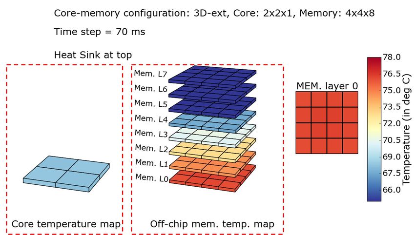
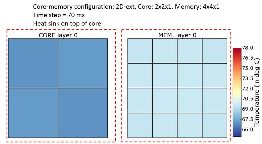
CoMeT: Integrated Core and Memory Thermal Simulation Toolchain 13

 Table 1. Core and Memory Parameters

 Core Parameter Value
 Number of Cores 4
 Core Model 3.6 GHz, 1.2 V, 22 nm, out-of-order, 3 way decode, 84
 entry ROB, 32 entry LSQ
 L1 I/D Cache 4/16 KB, 2/8-way, 64B-block
 L2 Cache Private, 64 KB, 8-way/64B-block
 Memory Parameter Value
 3D Memory (3D-ext, 2.5D, 1 GB, 8 layer, 16 channels, 8 ranks, 1 bank per rank,
 3D-stacked) Configura- closed page policy, 29/20/15 ns (latency), 7.6 GBps (per
 tion channel bandwidth)
 2D Memory Off-chip Con- 2 GB, 1 layer, 1 channel, 4 ranks, 4 bank per rank, closed
 figuration page policy, 45 ns (latency), 7.6 GBps (per channel band-
 width)

 Table 2. List of Benchmarks

 Benchmark Suite Selected Benchmarks
 PARSEC 2.1 dedup, streamcluster, vips, bodytrack, swaptions, blackscholes
 SPLASH-2 lu.cont, water.nsq, radiosity, raytrace, barnes, cholesky
 SPEC CPU2017 lbm, gcc, imagick, nab, x264, exchange

and obtain performance, power, and temperature metrics for various workloads. Thermal simulation
is invoked periodically with an epoch time of 1 ms.

4.2 Thermal Profile for Various Architecture Configurations
We present the thermal behavior of cores and memories for each of the four core-memory con-
figurations supported by CoMeT. We consider lbm benchmark from the SPEC CPU2017 suite and
execute its multiple instances, one on each CPU core. The temperature trace generated during the
simulation is used by HeatView to create a video of the thermal pattern of various cores and memory
banks. While the video for the entire simulation can be accessed online at tinyurl.com/cometVideos,
Figures 6, 7, 8, and 9 present snapshots taken at 70 ms of simulation time for each of the four
architectures.
 Figure 6 presents the temperature profile of cores and the external DDR memory. Since the
memory and core are on two separate chips, we observe that the cores have relatively lower
temperatures than memory banks due to the memory-intensive nature of the lbm benchmark.
Figure 7 shows the temperature profile of cores and an external 8-layer 3D memory. As cores
and memory banks are physically located on different chips, they do not influence each other’s
temperature and have different thermal profiles. We see that the memory banks attain significantly
higher temperatures. We also observe that, due to the heat sink at the top of the 3D memory, the
temperature of the lower layers is higher than that of the upper layers, with a gradual decrease as
we move upwards of the memory stack. While this core-memory configuration (3D-ext) differs from
2D-ext only in terms of using an external 3D memory compared to a DDR memory, we observe
that the cores in 3D-ext (Figure 7) are relatively hotter than the cores in the 2D-ext (Figure 6)
because of faster execution enabled by the 3D memory. Such insights enabled by CoMeT due to

 , Vol. 1, No. 1, Article . Publication date: September 2021.
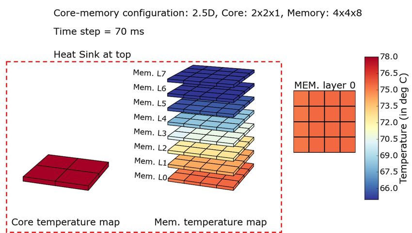
14 Siddhu et al.

Fig. 6. Thermal profile of core and memory at 70 ms when executing lbm benchmark on 2D-ext core-memory
configuration.

Fig. 7. Thermal profile of core and memory at 70 ms when executing lbm benchmark on 3D-ext core-memory
configuration.

the integrated core and memory thermal simulation cannot be easily quantified (accurately) when
using a standalone trace-based simulation infrastructure.
 Figure 8 shows the temperature profile of cores and 3D memory integrated on the same package
in a 2.5D configuration. Compared to the previous case of 3D-ext (Figure 7), we observe that core and
memory are thermally coupled in the 2.5D core-memory configuration, resulting in significantly

, Vol. 1, No. 1, Article . Publication date: September 2021.
CoMeT: Integrated Core and Memory Thermal Simulation Toolchain 15

Fig. 8. Thermal profile of core and memory at 70 ms when executing lbm benchmark on 2.5D core-memory
configuration.

Fig. 9. Thermal profile of core and memory at 70 ms when executing lbm benchmark on 3D-stacked core-
memory configuration.

higher temperatures for the same lbm workload. As the memory gets heated, it results in elevated
core temperatures, even for a memory-intensive workload. Moreover, the core is further away from
the heat sink, reducing its heat dissipation capability. We observe that the upper memory layers are
slightly hotter than the corresponding layers in an external 3D memory while the lower layers are

 , Vol. 1, No. 1, Article . Publication date: September 2021.
16 Siddhu et al.

 Fig. 10. Detailed/2D view of each layer for the 2.5D configuration, corresponding to Figure 8

significantly heated. This is because the upper layers are closer to the heat sink and away from the
cores leading to reduced coupling. We also observe from our temperature data (not visible in the
figure) that the left-most portion of the memory is relatively cooler (∼0.4°C) than other portions, as
the free space between the core and memory provides a cooling surface.
 In Figure 9, we show the thermal profile for a 3D-stacked configuration with one layer of four
cores stacked over an 8-layer 3D memory. We observe that any layer of the memory is hotter than
the corresponding layer in the 3D-ext or 2.5D core-memory configuration due to the increased
stacking of cores on top of the 3D memory, limiting the heat dissipation paths further, raising the
temperature.
 To illustrate the feature of HeatView to create thermal maps with detailed layerwise details (2D
view), we use the 2.5D configuration (Figure 8) as an example. The corresponding layerwise plot is
shown in Figure 10 and provides more details of each layer.

4.3 Thermal Profile for Various Benchmarks
Using CoMeT , we are able to analyze the performance, power, and thermal profile for core and
memory for various benchmark suites. Figure 11 shows the core, memory temperature, and ex-
ecution time for PARSEC 2.1, SPLASH-2, and SPEC CPU2017 benchmarks running on a four-core
system with an off-chip 3D memory (3D-ext architecture). A four-core system with a heat sink has
sufficient cooling paths. However, with higher power dissipation in cores, we see temperatures rise
to 70◦ C (on average).
 Most benchmarks in PARSEC 2.1 and SPLASH-2 suite are multi-threaded and compute-intensive.
So the average DRAM access rate remains low for these benchmarks throughout their execution.
However, due to the high density in 3D memories, the leakage power (temperature-dependent)
dissipation contributes significantly to overall memory power dissipation. Furthermore, stacking
increases the power density, resulting in memory temperatures of around 71◦ C (increasing with
memory access rate). For the SPEC CPU2017 suite, lbm is a memory-intensive benchmark with a

, Vol. 1, No. 1, Article . Publication date: September 2021.
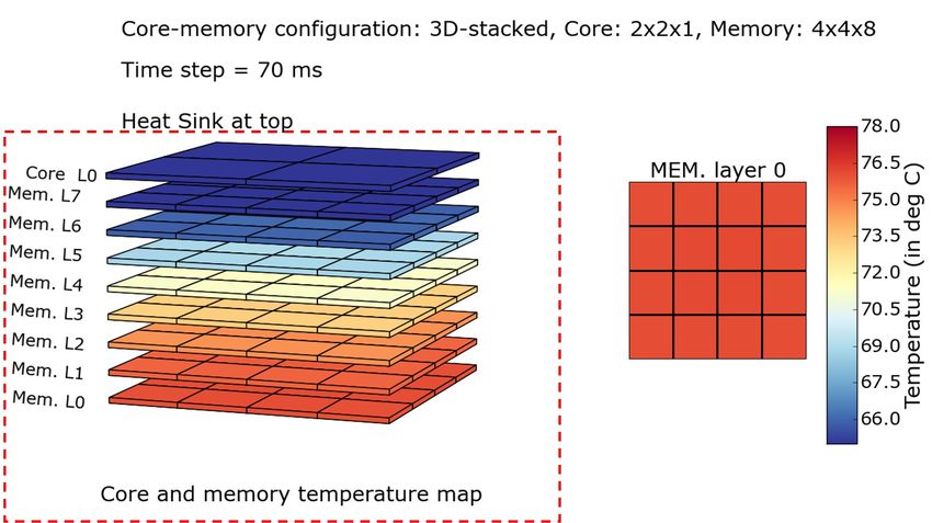
CoMeT: Integrated Core and Memory Thermal Simulation Toolchain 17

 Core Temperature Memory Temperature Execution Time
 80 1,000
 Core / Memory Temperature (◦ C)

 750

 Execution Time (ms)
 75

 500

 70
 250

 65 0
 c
 up ter ips ack ons les ont .nsq ity ace nes sky lbm gc gick nab x264 ange
 dedmclus v dytr apti kscho lu.c ater adiosraytr barchole a h
 rea bo sw blac w r im exc
 s t

Fig. 11. Temperature for three different benchmark suites running on 4 cores and off-chip 3D-DRAM memory
architecture: PARSEC (with simmedium input size), SPLASH2 (with small input size), and SPEC CPU2017
(with 100 million instructions)

high average DRAM access rate (as high as 108 accesses per second), which results in significantly
higher memory temperatures than for other benchmarks.

4.4 Case Study: Thermal-Aware Scheduler and DVFS
We show in this section a case study of the analyses that are possible with CoMeT and demonstrate
some trends that appear in stacked core-memory configurations. We employ the Linux ondemand
governor [38] with DTM as an example. The ondemand governor increases or decreases per-core
V/f-levels when the core utilization is high or low, respectively. DTM throttles the chip to the
minimum V/f-level when some thermal threshold is exceeded and increases the frequency back to
the previous level if the temperature falls below the thermal threshold minus a hysteresis parameter.
In this experiment, we set the two thresholds to 80◦ C and 78◦ C. The temperature is initialized to
70◦ C peak to emulate a prior workload execution.
 We execute the PARSEC swaptions with four threads to fully utilize all processor cores. Figure 12
depicts the temperature and frequency throughout the execution. Swaptions is compute-bound and
hence the ondemand governor selects the highest available frequency. The temperature limit of
80◦ C is reached fast, and DTM reduces the frequency until the temperature has decreased, leading
to thermal cycles as shown in the figure, where the frequency toggles between a low and a high
value. The peak temperature is not observed on the cores but on the memory layers, as explained
in Section 4.2.
 This simulation uses a 3D-stacked architecture—enabled by CoMeT —and shows some interesting
trends. The temperature on the core layer is directly affected by DTM. Upon thermal throttling, the
temperature immediately reduces almost exponentially, e.g., at 203 ms (Point A). It takes several
milliseconds until the temperature at layers farther away from the core layer reduces (in this
example 5 ms), during which the temperature overshoots the thermal threshold. Similarly, when
returning to normal operation, the temperature of the hotspot reacts with a significant delay to
DTM decisions. This delay is because the hotspot’s location (lowest memory layer) is far from
the layer most affected by DTM (core layers). This is unlike in the traditional 2D architectures,

 , Vol. 1, No. 1, Article . Publication date: September 2021.
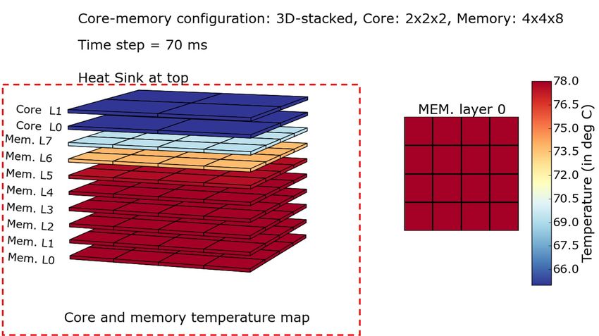
18 Siddhu et al.

 Core Layer (C0) Memory Layers L0 – L7 (8×)

 80
 L0
 Temperature (◦ C)

 75

 70
 L7
 C
 65

 60 A
 Frequency (GHz)

 4
 3
 2
 1
 0 20 40 60 80 100 120 140 160 180 200 220 240 260 280
 Time (ms)

Fig. 12. Transient temperature of the hotspot in each of the nine layers of a 3D architecture (one core layer,
eight memory layers). The memory layer farthest from the heatsink forms the overall system hotspot, and
determines when DTM throttles the system.

where the two coincide (thermal hotspot in the cores). Such different trends require novel power
and thermal management policies, which can be easily evaluated on CoMeT using the provided
interfaces presented in Section 3.5.

4.5 Parameter Variation
4.5.1 Increasing the Number of Cores. We study the performance and thermal effect of increasing
the number of cores (and threads) for the PARSEC workloads running on 3D-ext configuration. We
increase the number of cores from 4 to 16 and observe that some of the PARSEC workloads (such as
bodytrack, streamcluster, vips, swaptions) are able to utilize parallelism more effectively (Figure 13).
Workloads such as blackscholes and dedup either have a significant serial phase or imbalanced
thread execution time, thereby obtaining a limited speedup with a marginal increase in temperature.
 For blackscholes, we see a speedup of ∼1.5x (compared to a 4x increase in the number of cores)
as it spends most of the execution time in the serial phase. This experiment also demonstrates that
CoMeT can be configured for various numbers of cores (and memory banks).
4.5.2 Increasing the Number of Core Layers. Until now, all our experiments have considered cores on
a single layer. Here, we demonstrate the ability of CoMeT to perform thermal simulation for multiple
layers of cores. We consider the same 3D-stacked core-memory configuration corresponding to
Figure 9 but extend it to have two layers of cores and, therefore, have a total of 8 cores. We execute
the lbm workload, with one instance of lbm benchmark running on each core (a total of 8 instances),
as done in previous sections. The temperature pattern of various layers of core and memory is
shown in Figure 14. We observe that, compared to Figure 9 with only a single layer of the core,
the presence of an additional layer of core on the top raises the temperatures of the bottom layers
significantly. In this specific experiment, the presence of two core layers raises the bottom layer
temperature by ∼11 °C over the temperature due to a single core layer.

, Vol. 1, No. 1, Article . Publication date: September 2021.
CoMeT: Integrated Core and Memory Thermal Simulation Toolchain 19

 Core Temperature Rise Memory Temperature Rise Speedup
 10 5
 Temperature Rise (◦ C)

 8 4

 Speedup
 6 3

 4 2

 2 1

 0 0
 dedup streamcluster vips bodytrack swaptions blackscholes

Fig. 13. Normalized speed-up and increase in steady-state temperature for 16 core configuration (as compared
to 4 core)

Fig. 14. Thermal profile of core and memory at 70 ms when executing lbm benchmark on 3D-stacked core-
memory configuration with 2 layers of core on top of 8 layers of memory.

 This experiment clearly demonstrates the versatility of CoMeT in adapting to different kinds of
core-memory configurations with single/multiple layers of cores integrated with single/multiple
layers of memory. Such a capability enables CoMeT to analyze the performance, power, and thermal
behavior of various emerging core-memory configurations and identify various optimization
opportunities within them. We strongly believe that CoMeT could help identify many newer
research problems as well as evaluate their proposed solutions.

4.6 Overhead Analysis
Compared to HotSniper, which runs performance and thermal simulations for cores, CoMeT executes
thermal simulations for memory as well. Figure 15 compares simulation time for the PARSEC

 , Vol. 1, No. 1, Article . Publication date: September 2021.
You can also read