BASSINGTON GAS STOVE INSTALLER AND USER INSTRUCTIONS - PLEASE LEAVE THIS BOOKLET WITH THE CUSTOMER - Penman Collection
←
→
Page content transcription
If your browser does not render page correctly, please read the page content below
BASSINGTON
                         GAS STOVE

                       INSTALLER AND USER
                          INSTRUCTIONS
                            For use in UK & Ireland on
                 Natural Gas (G20) at a supply pressure of 20mbar
                                         or
                  Propane (G31) at a supply pressure of 37mbar

      PLEASE LEAVE THIS BOOKLET WITH THE CUSTOMER

GBU / REV: D / 05/21
1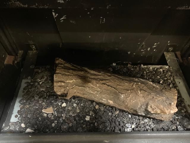
2
CONTENTS
INSTALLATION INSTRUCTIONS

IMPORTANT NOTES               PAGE 04

TECHNICAL INFORMATION         PAGE 05

DIMENSIONS                    PAGE 06

INSTALLATION                  PAGE 07

COMMISSIONING THE STOVE       PAGE 12

CHECK FOR SPILLAGE            PAGE 14

CUSTOMER HANDOVER             PAGE 15

SERVICING                     PAGE 16

SERVICE AND MAINTENANCE LOG   PAGE 18

COMMISSIONING CHECK LIST      PAGE 20

USER INSTRUCTIONS

GENERAL NOTES                 PAGE 22

IMPORTANT NOTES               PAGE 22

MANUALLY OPERATED STOVE       PAGE 22

REMOTE CONTROL STOVE          PAGE 23

BATTERY REPLACEMENT           PAGE 29

ERROR CODES                   PAGE 29

3
INSTALLATION INSTRUCTIONS
IMPORTANT NOTES
This stove is a log fuel effect radiant convector only. Before installation, ensure that the local
gas supply distribution network is adequate and that the appliance can be installed as such
to ensure it meets the safe working parameters as indicated on the appliance data badge.
The data badge is located at the rear of the stove. The appliance is only for use with natural
gas (G20) & propane gas when using a conversion kit (G31) The appliance must always be
installed in accordance with these Instructions and current British standards and the Gas
Safety installation and use regulations (1998). All gas work must be carried out by a
competent qualified installer registered with the appropriate regulatory body. Failure to
install the appliance correctly may lead to prosecution.
Note: Please see below the relevant standards in order for the installation be compliant. In
the absence of any technical detail within the manufactures installation instructions the
British standards must be adopted as a point of reference to ensure a safe installation.
BS 5440 Part 1
BS 5440 Part 2
BS 4543 Part 2
BS 5871 Part 1
BS 6891
BS 8303
Current edition of the Building Regulations – England and Wales
Current edition of the Building Standards –Scotland
Current edition of the Building regulations – Northern Ireland
Current edition of Domestic gas Installations – Republic of Ireland
Installation of a manual flue damper on this appliance is prohibited, and where this appliance is
installed to an existing flue incorporating a manual flue damper or restrictor plate, the damper and
restrictor plate must be permanently fixed in the open position or removed completely.
If the chimney has previously been used to burn solid fuel, the chimney must be swept
before the stove is installed, both for use with or without a liner.
A flue flow test should be carried out to check the effectiveness of the flue/ chimney and ensure
that there is no leakage into another part of the premises (including any roof space or void) or, as
appropriate, other adjoining premises. This is particularly important where a number of chimneys
combine into a multiple chimney stack. Smoke coming out of a terminal which is not the correct
terminal, or a down-draught or no-flow condition, indicates an unsatisfactory flue/chimney.
After completion of a satisfactory flue flow test, a spillage test should be carried out, with the
appliance connected and operating, to check that the products of combustion are being safely
removed.
4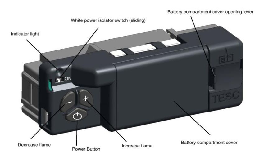
The stove is fitted with a spillage monitoring system consisting of a thermal switch. This
system is not adjustable, and must not be put out of action when the appliance is in
operation, if the switch is removed it would be deem the appliance to be unsafe and must
immediately be disconnected from the gas supply and a warning notice issued. If any parts

of the spillage monitoring system require replacement only original manufacturers’ parts
must be used.

All surfaces except the controls are considered to be working surfaces, all care should be taken to
minimise the risk of burns to vulnerable and young children when the stove is in operation.

The stove must not be used or installed for any other purpose other than as a room heater and a
decorative stove.
The stove must not be operated with the door open, without the door attached or the
glass in the door damaged, broken or missing. It must not also be operated without the
correct flue or chimney system, and it must not be operated unless it has been installed &
commissioned in accordance with these instructions.

TECHNICAL INFORMATION

                 GAS                             NATURAL GAS                      PROPANE

       APPLIANCE GAS CATEGORY                         I2H                            I3P

     HEAT INPUT (NETT) HIGH/LOW                  6.1kW/3.9kW                    5.7kW/3.0kW

           SUPPLY PRESSURE                     20 mbar ±1 mbar                37 mbar ±1 mbar

           GAS CONNECTION                         8mm tube                        8mm tube

          GAS CONSUMPTION                         0.66cu.m/h                     3.9 litre/min

              NOX CLASS                               5                               5

           EFFICIENCY CLASS                           2                               2

               INJECTOR                         400 MH(7x0.76)             190 Single hole (1.2 Dia)

         FLUE RESTRICTOR RING                   64mm diameter                  64mm diameter

                                          125mm Diameter or 100mm        125mm Diameter or 100mm
           FLUE CONNECTION
                                            Diameter with adapter          Diameter with adapter

           THERMAL SWITCH                          120 deg C                      120 deg C

5
DIMENSIONS

GAS BASSINGTON WITH STANDARD LEGS

GAS BASSINGTON WITH SKIRTED LEGS

GAS BASSINGTON WITH BASELINE LEGS

6

INSTALLATION
Install the stove in accordance with the
requirements given below. The gas
connection will be to the rear of the
stove therefore it is advisable to
prepare the pipe work in advance of
installing the stove.
Fix the legs to the stove using the bolts
provided. When the stove is in the
desired position, if required, fix the
brackets provided to the back feet and
level the stove using the levelling
screws, then mark the hearth through
the holes, remove the stove, and drill
and plug the hearth for securing the stove.
Fig.1 Door screw
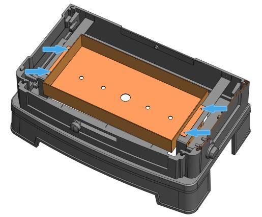
FITTING THE BURNER INTO THE STOVE BODY
Slacken the screw securing the door shown in
Fig.1 and open the door. Position the burner
tray into the stove, ensuring that the pilot is
located to the rear. There are 4 screws already
fitted to the burner tray brackets inside the
stove. Remove these before positioning the
burner tray and reuse them to secure in place.
See Fig.2.
Fit the thermal switch and the pilot cover prior
to installing the stove.
FITTING THE THERMAL SWITCH Fig.2 Fitting the burner
Fit the thermal switch to the bracket positioned
at the draft diverter at the rear of the
stove, with the 2 screws provided – see
Fig.3.
IMPORTANT: THE STOVE MUST NOT BE
OPERATED WITHOUT THIS THERMAL
SWITCH CORRECTLY FITTED
Fig.3 Thermal switch bracket
7
FITTING THE THERMAL SWITCH GUARD
Using the two screws already fitted to the rear of the stove, secure the thermal switch guard
to the rear of the appliance. See Fig. 4

                              Fig.4 Fitting the thermal switch guard

POSITIONING THE STOVE
Clearances from non-combustible material in the fireplace opening must be at least 160mm on the
left side, 160mm on the right hand side and 105mm at the back. See Fig. 5. These distances must
be extended to a minimum clearance of 400mm from any combustible material.

    Fig.5 Clearances

8
HEARTH
The stove must stand on a fireproof hearth made of non-combustible material of a minimum
thickness 12mm and be of sufficient size to accommodate the stove.
FIRE SURROUND & SHELVES
It is recommended that a fire surround should not be closer than 400mm from the stove in all
directions, if manufactured from a combustible material. A combustible shelf may be fitted
provided that it is not more than 150mm deep and there is at least 400mm
clearance from the top of the stove.
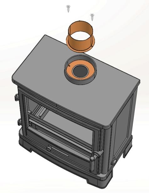
FLUE CONNECTION
The flue must be a minimum of 3m high and at least 100mm diameter or equivalent area.
Horizontal or negative gradients in the flue pipe should be avoided. A minimum height of 600mm
from the stove should be established before any significant change in the direction of the flue.
For warranty compliance it is recommended that the flue should be lined. Alternatively other
methods for unlined installations can be found within the current British Standards. Installation
without a liner can become problematic and failures in these instances would not be covered
under the appliance warranty.
When connecting the circular liner to the appliance spigot an appliance adaptor must be used and
sealed in place, using an appropriate temperature rated sealant. The sealant must be able to
withstand temperatures of up to 400°C.For decorative purposes, the flue liner may be sleeved
over with a 125mm diameter vitreous connecting flue pipe. Alternatively a 100mm diameter
connecting flue pipe can be fitted directly into the appliance spigot and sealed appropriately. All
methods of installation must also be in accordance with the current British standards BS 5440 Part
1 & 2 and BS 5871 Part 1. Terminals and associated flue system materials used must also be in
compliance with the current British standards.
Should there need to be a deviation within the
first 600mm of the connecting flue pipe to
accommodate building fabric obstructions, it
would be acceptable to offset the vertical
gradient. This offset must not exceed a distance
of 200mm from the internal diameter of each
component fitting used or liner, and the angle no
greater than 45° (see Fig. 6). In this instance it
would not be advisable to install the restrictor
ring within the flue collar, but all necessary tests
must be undertaken to ensure the performance
of the appliance is satisfactory.
Fig.6 Flue offset
9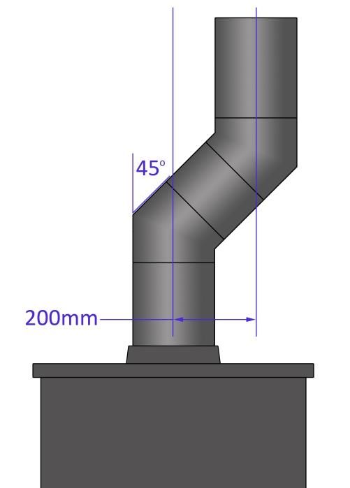
FLUE RESTRICTOR RING
This stove is supplied with a flue restrictor ring and not to be confused with a restrictor plate for
use where the flue draught is excessive. The restrictor ring must not be fitted if the stove is to be
connected to a pre-cast flue or a masonry chimney with a diameter of 100mm/125mm. There may
however be certain circumstances where fitting the restrictor ring causes the fire to fail the
spillage test. In such cases the restrictor ring must be removed. After removal, conduct the spillage
test again. Further investigation as to the chimney’s suitability must be conducted by the installer
in these instances.
FLUE SPIGOT
RESTRICTOR RING
(IF REQUIRED)
Fig.7 Flue connections
VENTILATION
This appliance only requires normal adventitious ventilation, however new build properties may
need additional measures due to their air tightness. Reference to BS5871 Part 1 should be sought
to ensure all conditions are met for the UK. For Ireland reference should be made to the current
edition of IS 813 “Domestic gas installations” to ensure absolute compliance.
GAS CONNECTION
The gas supply connection is at the right hand side of the stove on the inlet to the gas valve. The
stove will come supplied with an 8mm restrictor elbow with a burner pressure test point
incorporated for ease of connection. This must only be connected to the gas supply pipe
connected to the gas valve. A flexible gas hose of any description is not permitted to be used on
this appliance downstream of the provided restrictor elbow. The gas supply must be purged and
any loose debris within the pipe must be cleared prior to ensure there are no blockages as this can
cause damage to the gas valve when lighting. Connect the gas supply pipe and test for gas
tightness.
VERMICULITE DISPERSAL MEDIUM
Place the black vermiculite supplied into the burner tray. Completely fill the burner tray. Care
should be taken not to compress it down and to ensure a level surface to allow for a level base
when placing the logs.
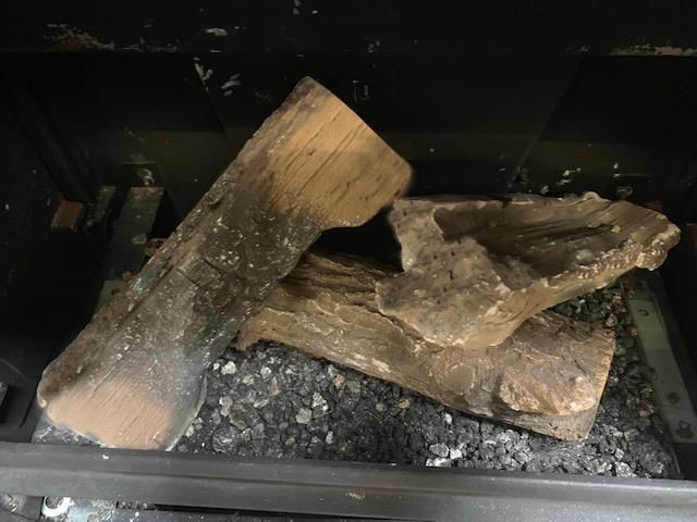
10POSITIONING THE LOGS
1. Fit log A as shown in Fig.8.
2. The Embaglow can now be fitted on top of the black vermiculite as directed on the back
of the packet. Take care not to put Embaglow material too near the pilot as this can
interfere with ignition.
3. Position log B & log C as shown in Fig.9.
4. Close the door and secure with the locking screw as shown in Fig. 1.
Fig.8 Log A position
Fig.9 Log B & C position
11COMMISSIONING THE STOVE
MANUALLY OPERATED STOVES
Once the fire is in place, connected, flued correctly, and the logs are in place, you can proceed with
lighting the stove and ensuring the all the features are working correctly.
The control knob is located behind the right-hand foot of the stove.
The pilot light is centrally located.
Should the stove be extinguished for any reason wait 3 minutes before attempting re-ignition.
Connect a suitable pressure gauge to the inlet pressure test point to check the correct inlet
pressure.
Fig.10 Manual control knob and Fig.11 Orientation on appliance
markings
LIGHTING THE PILOT
Depress control knob fully. Whilst depressed turn knob slowly through 80° anti-clockwise to PILOT
setting. Continue to depress the control knob, a click should be heard and the pilot should light.
Repeat until pilot is visibly lit. If necessary, the operation of the spark can be viewed by
temporarily opening the front door.
Keep knob depressed at this point for 10-15 seconds and release the knob. The pilot light will
remain lit.
HIGH SETTING
If the pilot is not already lit, light the pilot as described above. With control knob at PILOT setting,
depress and turn anti-clockwise to HIGH setting and release the knob.
LOW SETTING
If the stove is already lit on HIGH setting, ignite stove to HIGH setting as described above.
12Turn the control knob progressively in an anti-clockwise direction until the desired level is achieved, up to the LOW setting. Check that the supply pressure is 20 mbar ± 1 mbar. TURNING THE STOVE OFF From any heat setting, depress control knob fully and turn clockwise to PILOT position. Disconnect. TURNING THE PILOT OFF From any heat setting or the PILOT position, depress control knob fully and turn clockwise to OFF position. REMOTE CONTROL STOVES Once the fire is in place, connected, flued correctly, and the logs are in place, you can proceed with lighting the stove and ensuring the all the features are working correctly. The fire control unit is located behind the right-hand foot of the stove. The pilot light is located centrally at the rear of the burner. Should the stove be extinguished for any reason wait 3 minutes before attempting re-ignition Connect a suitable pressure gauge to the inlet pressure test point to check the correct inlet pressures. Fit AA batteries to the fire control unit. The control requires 3 AA size alkaline batteries to be inserted under the battery compartment cover. The orientation of these is shown moulded into the battery compartment. After fitting the batteries and replacing the cover the fire can now be operated. Slide the Master switch to the right to the ON position (I symbol). 13
To start the fire, press the ON/OFF button and hold for 1 second then release. The burner will
within around 1 to 10 seconds ignite and adjust to the maximum power setting. This can take
longer on the first lighting as it has to clear out any air locks

Check that the supply pressure is 20 mbar ± 1 mbar

The power of the burner can be adjusted up and down by pressing the + and – buttons.

To stop the fire, simply press the power button again and the burner will stop. Disconnect the
pressure gauge, replace the test point sealing screw and test for gas soundness.

Once the fire has been successfully lit and extinguished, you can then put batteries in the Remote
control and check that this is functioning correctly (See user instructions including how to set the
time and date on the handset).

CHECK FOR SPILLAGE

Close all doors and windows in the room containing the appliance. Light the stove and set the
control unit to ‘HIGH’, leave the appliance running for 5 minutes.

Apply a smoke match along the bottom edge of the draught diverter, the smoke match can be
inserted at least 5-10mm . The spillage test will be deemed to satisfactory if the smoke is
drawn into the stove. If in doubt wait a further 10 minutes and then repeat the test.

If still in doubt and the flue restrictor ring is fitted, remove the ring and repeat the spillage test.

If there is a nearby room with an extractor fan then the spillage test must be repeated with the fan
running and take into account any other factors which may adversely affect flue/chimney
performance, e.g. operation of tumble driers or forced-air heating systems in the room housing
the appliance or any adjoining room (with interconnecting doors open).Passive houses may also
have an adverse effect. If in doubt disconnect the appliance permanently from the gas supply,
issue the appropriate paperwork and labels and seek further advice.

NOTIFIABLE WORK – BUILDING CONTROL

As a Gas Safe registered engineer, in England and Wales you must report the installation of heat
producing gas appliances, and the installation of heating and hot water systems connected to the
gas appliance, through our online notification system. By reporting your safe work in this way the
Gas Safe register will ensure that a Building Regulations Compliance certificate will be sent to the
homeowner or builder and they will also advise the relevant Local Authority building control
department of the work on your behalf. This certificate is important and will form part of the
warranty agreement.

There is no mandatory requirement to notify gas work in Northern Ireland or Scotland. However,
we do encourage businesses to provide customers with a quality record of work; this can be done
by making voluntary Declarations of Safety. You can do this online in the same way as mandatory

14
notifications and once the notification has been received Gas Safe Register will provide your
customer with a Declaration of Safety certificate.

You should report the installation of any new or replacement flued gas appliances and non-flued
fixed appliances that provide heating or hot water for your customers.

CUSTOMER HANDOVER

Hand these Instructions to the customer and advise the customer how to use the stove.
Explain to the customer that the stove has a flame failure and spillage monitoring system.
Point out the explanation of this system is in the Operating the Stove section of the instructions.
Advise that if the monitoring system repeatedly shuts off the stove, it must be switched off and not
used until it has been inspected by a competent person.
Advise that if the fire goes out for any reason, wait at least three minutes before relighting.
Advise the customer that due to the newness of materials the stove may give off a slight smell for a
period of time after commissioning. This is quite normal and any odours should disperse after a
few hours operation.
Stress that no extra logs must be added over and above those supplied with the appliance and that
any replacements must only be authorized spares.
Recommend that the stove is regularly serviced and the flue system checked by qualified persons.
Explain to the following information to customer regarding condensation:
IMPORTANT NOTE ABOUT CONDENSATION
When the unit is turned on, condensation will initially form on the glass. This is a normal
occurrence. Water vapour is created when gas is burned. This will condense against the cold glass.
This condensation will form every time the unit is switched on from cold. The condensation will
disappear once the unit is at operating temperature.

In order to quickly get the unit to operating temperature, we strongly recommend you let the unit
burn on high for at least 15 minutes. This means you do not switch to low setting during this brief
period and is the fastest way to make sure the condensation disappears.

If the unit is immediately set to a lower setting after switching on for the first time, the glass will
remain wet for a long time, and this will result in it becoming dirty more quickly.

The condensation which forms on the internal surface of the glass during operation can collect
airborne contaminates which may cause staining. These contaminates can build up over a period
of time, giving the appearance of misty/cloudy viewing area and if left, may result in the need for
the glass to be replaced. Adequate service and maintenance combined with the correct
operational use will reduce the risk of this happening.

When cleaning do not use any of the following cleaning materials:

15
Hard (abrasive) sponges, steel wool, abrasives and cleaners with ammonia or acid (including citric
acid ), paper towels, ceramic cook top cleaner.
Only use water or mild detergents. We recommend using Percy Doughty Glass Cleaner available
through all good stove retailers.
SERVICING
It is essential that the stove is regularly serviced, and the flue system checked by a qualified
person.
SERVICING INSTRUCTIONS
The stove is fitted with a spillage monitoring system consisting of a thermal switch connected to a
thermocouple interrupter. This system is not adjustable and must not be put out of action. If any
parts of the spillage monitoring system require replacement only original manufacturer’s parts
must be used.
The thermal switch rating is 120ºC. Quote this rating if ordering a new switch.
The following servicing procedure should be carried out regularly and only by a qualified person.
Visually inspect the appliance for signs of spillage safe operation, check position as per
manufacturer’s instructions, including clearances and proximity to combustible materials
Ensure fixing is sufficient and the appliance is stable
Check if gas pipe is sleeved through the wall and protected in accordance with BS6891
Check the ventilation is correct
Ensure that the fire is turned off and is cold. Slacken the screw securing the door (Fig.1) and
open the door.
Remove the ceramics in the reverse order to that described in the POSITIONING THE LOGS
section. Due to the intense temperatures reached in the fire, some surface cracks may
appear on the ceramic components. This is quite normal and will not affect the safe
operation of the fire.
Remove any deposition of dirt, lint etc. carefully from the burner flame strip, tray and pilot
assembly with a soft brush
Replace the ceramics as described in POSITIONING THE LOGS section (Fig.4&5).
Check the internal combustion chamber for any signs of damage or paint failures (a high
temp paint can be used to rectify in these instances. Care must be taken not to contaminate
the ignition system or burner with paint overspray)
16 Ensure all the injector ports are clear and free from debris (care must be taken not to
damage these parts)
Ensure the spark generator system is working correctly and the ignitor probe is in tact
Ensure the thermocouple tip is clean and free from any carbon build up
Clean the glass taking care not to soak the rope with cleaning solution
Check all rope and door seals for signs of deterioration (If damaged or worn in a way that
appliance has become unsafe then they must be replaced and the fire must be turned off
and not be used until such time that they are)
Close the stove door, replace the screw securing the door
Check the supply pressure as described in the TECHNICAL INFORMATION section (P.5)
Complete a gas tightness test
Check all controls, safety devices including the flame picture and that the fire is working
safely accordance with the manufacturer’s instructions
Check the flue in accordance with regulation 26(9) Ensure there are no signs of metal
fatigue, distortion, discolouration, sooting and distress
Ensure correct operation of the flue and perform a spillage test as described in CHECK FOR
SPILLAGE section (P.13)
Complete service and maintenance log on page 18
DOOR SEAL
If required the door seal can be adjusted/tightened as follows:
1. Slacken door locking screw and open the stove door.
2. Slacken handle locking screw and remove handle.
Move spacer Spacer washers
3. Remove 1 spacer washer and move to the other
side of the door. washer to here
4. Reassemble in reverse order.
Handle locking screw Door locking screw
17SERVICE AND MAINTENANCE LOG SERVICE DATE PERFORMED BY WORK PERFORMED 18
SERVICE AND MAINTENANCE LOG
SERVICE DATE   PERFORMED BY   WORK PERFORMED

19
COMMISSIONING CHECKLIST
This checklist must be completed by the installer and handed to the customer for future reference.

Customer Name:                                             Telephone:

Address:

Appliance make and model:

Appliance serial number:

Commissioned by:                                           Gas Safe register no.:

Company Name:                                              Telephone:

Company address:

                                                           Commissioning date:

Gas Safe register notification no.:

Site Requirements                                                                                       Yes   No
Was the chimney checked to ensure it only serves 1 flue/fire, has no obstructions and is
continuous?
Has any debris at the base of the chimney been removed?

Have damper and register plates been removed or locked in the fully open position ensuring
correct size of flue is maintained?
If previously used for solid fuel, has the chimney been thoroughly swept?

Has the chimney been inspected prior to fitting the appliance to ensure that it is in good
condition?
Has the structure of the chimney been checked for leakage using a smoke pellet test? (See
BS5440-1 for details).

Ventilation                                                                                             Yes   No
Does the installation require any additional ventilation requirements as detailed in this instruction
manual?
Hearth Requirements                                                                                     Yes   No
Is the hearth constructed from non-combustible material?

Is the hearth a minimum of 12mm thick with a minimum floor to top surface of 50mm? (BS5871)
or as per manufacturer’s instructions?
Firebox and Fuel bed                                                                                    Yes   No
Has the fuel bed (logs,vermiculite) been fitted to the manufacturer’s instructions?

20
Gas Supply Yes No
Has an isolation tap/restrictor inlet elbow been fitted for servicing?
Has the gas supply been thoroughly purged prior to connection to remove any debris?
Has a gas tightness test been completed prior to breaking into the gas supply and following
completion of the installation? (IGEM/UP/1B)
Record burner gas pressure reading? If only the supply pressure is available a gas rate must be
undertaken. (GSIUR REG 26/9C)
Record dynamic inlet gas pressure (working pressure) reading (all gas appliances running).
Spillage Test Yes No
Installation passes smoke match test with any extractor fans turned on?
Installation Yes No
Has the appliance been installed and commissioned in accordance with the manufacturer’s
instructions?
Has the appliance been installed with the correct clearance to combustible materials as per the
manufacturer’s instructions?
The operation of the appliance and controls have been demonstrated to the customer including
battery replacement where applicable?
Has the appliance been registered with the Local Authority as detailed on the Gas Safe website
and is a legal requirement and forms part of the warranty?
IMPORTANT: Please ensure that the correct appliance category and gas type are marked on
the appliance data plate using permanent ink, see example below marked with ticks:
Customer’s signature:
(To confirm satisfactory demonstration and receipt of manufacturer’s literature)
Commissioning Engineer’s signature:
21USER INSTRUCTIONS
GENERAL NOTES
This stove has been individually designed to add charm and character to your home. Providing a
highly efficient heat source, the stove has the look and charm of a wood burning stove coupled
with the convenience of clean burning gas.
Due to the newness of materials the stove may give off a slight smell for a period of time after
commissioning. This is quite normal and any odours should disperse after a few hours operation.
IMPORTANT NOTES
The installation must be in accordance with current British Standards and National Regulations as
applicable, and must be carried out by a qualified installer. Under no circumstances should the
appliance be operated with the door open, without the door attached or the door glass damaged
broken or missing.
All surfaces except the controls are considered to be working surfaces. Most parts of the stove will
get hot during and after use. If young children, the elderly or infirm are likely to be near the stove,
then a suitable fireguard to BS8423 is recommended.
Do not drape clothes, fabrics or other combustible materials over the stove.
A combustible shelf may be fitted over the appliance provided that in the case of a 150mm or less
deep shelf there is at least 400mm clearance above the top of the stove.
The stove should not be used for any other purpose than as a room heater and a decorative stove.
MANUALLY OPERATED STOVE
The stove is fitted with a pilot light, pulse spark ignition and flame-sensing device.
The control knob is located behind the right-hand foot of the stove, see Fig.1 and Fig. 2 for details.
The pilot light is centrally located at the rear of the burner.
Should the stove be extinguished for any reason wait 3 minutes before attempting re-ignition.
The stove should not be used at a lower setting than the LOW position.
Fig.1 Manual control knob and markings Fig.2 Orientation on appliance
22Lighting the Pilot
Depress control knob fully. Whilst depressed turn knob slowly through 90° anticlockwise to PILOT
setting. A click will be heard and the piezo spark should light the pilot. Repeat until pilot is visibly
lit. If necessary the operation of the spark can be viewed by temporarily opening the front door.
Keep knob depressed at this point for 10-15 seconds and release the knob. The pilot light will
remain lit.
High Setting
If the stove is not already lit light the pilot as described above.
Turn the control knob anti-clockwise until the HIGH setting is reached.
Low Setting
If the pilot is not already lit, light the pilot as instructed.
With control knob at PILOT setting, depress and turn anti-clockwise to LOW setting and release the
knob.
Turning the Stove OFF
From any heat setting, depress control knob fully and turn clockwise to PILOT position.
Turning the Pilot OFF
From any heat setting or the PILOT position, depress control knob fully and turn clockwise to OFF
position.
REMOTE CONTROL STOVE
Should the stove be extinguished for any reason, wait 3 minutes before attempting re-ignition.
IMPORTANT: when starting the fire the burner usually takes around 3-10 seconds to ignite and
adjust to the maximum setting. This can take longer on the first lighting.
STOVE CONTROLS
This stove is fitted with a gas valve which can be operated via the remote control or using the
control unit which is located behind the right-hand foot of the stove. Fig. 3 shows the main
features of the controls.
The control requires 3 AA size alkaline batteries to be inserted under the battery
compartment cover. The orientation of these is shown moulded into the battery
compartment.
After fitting the batteries and replacing the cover the fire can now be operated.
Slide the Master switch to the right to the ON position (I symbol).
To start the fire, press the ON/OFF button and hold for 1 second then release. The burner
will within around 1 to 10 seconds ignite and adjust to the maximum power setting,
The power of the burner can be adjusted up and down by pressing the + and - buttons.
To stop the fire, simply press the power button again and the burner will stop.
NOTE: For safety reasons a button must be pressed and released for the command to be
recognised. Keeping hold of a button when pressing (unless otherwise instructed) will not be
recognised as a command press.
23STOVE CONTROL UNIT
Fig.3 Stove control unit
Indicator Light:
Off - Burner is in standby and ready for start, or already in continuous operation.
Fast flashing - Control unit is busy and will not accept commands.
Medium fast flashing - Control unit is preparing a (re)start of the burner.
Slow flashing - Control unit is detecting an error.
One short flash every 8 seconds - Low battery warning.
Always on - Burner is locked.
White Power Isolator Switch
Left position - Control unit is disconnected from all power supplies and does not
consume power.
Right Position - Control unit is powered and ready to operate.
Decrease Flame Button:
Burner in operation - Use this button to reduce the power level.
Increase Flame Button:
Burner in operation - Use this button to increase the power level.
Power Button:
Burner in operation - Use this button to stop burner operation.
In standby mode - Use this button to start burner operation.
Burner locked - Use this button to unlock the burner and to reset from error state.
If control unit is preparing to restart - Use this button to stop the restart and disable
further automatic starts.
Battery box:
Insert here 3x AA-type Alkaline batteries.
24REMOTE CONTROL HANDSET
Fig.4 Remote control handset
Fig. 4 shows the main features of the Remote control handset
The remote control handset requires 2 AA size alkaline batteries to be inserted under the battery
compartment cover. The orientation of these is shown moulded into the battery compartment.
To start the fire, with one hand grasp around the rear and both sides of the button area
control. The green unlock light will illuminate. Note: Keep a grip of the handset to keep it
unlocked and to continue to operate the command buttons.
With the other hand touch and hold a finger on the power button for about 3 seconds. A
short beep and a flash of the unlock light will happen.
When the word “pilot” appears at the bottom left hand corner of the display,
immediately release the power button.
A second flash of the unlock light and a longer beep will also sound at the time to release
the power button.
The fire should be lit within a few seconds.
25 If power button is held for more than a few seconds after second flash/beep/word pilot
appears, the command is ignored for safety reasons.
Similarly if it is released too soon before the word pilot appears, the command is also
ignored.
With this system, the control has been designed to ensure that only intended ignition of
the fire occurs.
To stop – with handset held to unlock it, press then release power button.
DETAILED USER INSTRUCTIONS
SETTING THE REMOTE CONTROL HANDSET
Upon successful insertion of the batteries in the handset
the display will be as shown in Fig. 5.
The handset will be supplied paired to the fire and all that
is required is to set the time of day and select if a 24h hour
clock or 12 hour clock display is required and if
temperature display is on Celsius or Fahrenheit.
SETTING THE TIME AND DATE
Holding the handset as described previously to unlock
the keypad, press and hold “SET” for a few seconds
and the display will be as shown in Fig. 6.
Set the display for 12 or 24 hour display - as always when
pressing the remote control buttons keep the control held Fig.5
to keep the green light on and therefore handset safety
feature unlocked. The H indicates that it is
time to set the timer to either 24 hour display or 12 Hour
(AM or PM) display. Press the + or – button on the handset
to toggle between the two settings. When you are ready to
confirm the setting you want press the “SET” button to
progress to setting the day of the week.
Setting the day of the week - Press and release the + and –
buttons until the correct day of the week is shown on the
display.
Mo = Monday, Tu = Tuesday, We = Wednesday, Th =Thursday,
Fr = Friday, Sa=Saturday and Su=Sunday
Press “SET” to accept the day of the week and to progress
to setting the Hour of the day. Note: Whilst doing this setup
pressing “SET” advances to the next display and pressing Fig.6
“MODE” will return you to the previous display setting.
26Setting the hour - press and release the + or – button to change the hour to the correct hour and press set to store and to move to setting the minute. Repeat this for setting the minutes. SETTING THE TEMPERATURE DISPLAY TO CELSIUS OR FAHRENHEIT. Press and release the + or - button to toggle between °C and °F. When the display shows the desired symbol, press and release the SET button to store the setting. As the main settings above have now been done, press and hold (not releasing straight away) the “SET” button for a few seconds and this will exit the setup menu. Alternatively you can press and release the set button several more times until the time of day is displayed on the handset. The control is now ready for use with the Fire Control. Note: the legend at the bottom shows the battery condition of both the batteries in the hand set and in the fire control alternately. RC = Remote control handset and FC = Fire control. The control is designed to get the most out of the batteries but when eventually the display shows they are spent (when the battery legend is an empty area) we recommend you change the batteries in the handset before they are flat, to avoid having to reprogram the time and date settings again. PAGING THE HANDSET If you have misplaced the handset (and it is in range of the fire), you can page it by pressing the + button only on the Control unit for around 5 seconds. The handset will flash and make a noise to help you to locate it. Once you pick up and grasp the handset to unlock it, the Control unit will detect this and so the sound stops. The flashing and sound will last for 60 seconds each time the handset is paged as described. If not found in 60 seconds, page again and so on. NOTE: PRESS “+” Button ONLY, NOT + and - Together as you will accidentally break the handset pairing and have to reset handset to factory state and pair again (see the pairing handset section if this happens). HANDSET PAIRING The handset should be supplied already paired with your fire, however if it becomes necessary to cancel the pairing and re pair it again do the following steps below. (NOTE: A new pairing can be accidentally started by accidentally pressing the plus and minus buttons together at the same time on the Control unit and held for 5 seconds. 27
Factory Reset of display handset
To reset a handset to factory conditions to enable it to be paired with a
control:
Hold the handset to unlock. Press and hold SET until handset beeps
and release the set button. PROG will be at the top left corner.
Press and release the MODE button until the word SETUP is flashing
in the top right corner.
Press and release SET to enter the SETUP menu.
Press and release the set button around 9 times until you see CA0
on the display.
Press then release the + (or – button) to change the display to CA1
and press and release the SET button again. The word TESC will
appear in the window to show that this handset is now reset and
ready to pair again.
Fig.7
Pairing the handset to the Fire control unit
With 2 good quality AA alkaline batteries in the handset in the direction
shown inside, if the handset can be paired with a control it will display
the word TESC as shown in Fig. 7.
The handset must be within 1 metre (3 feet) of the fire when pairing
After fitting the batteries and with the power isolator, slide switch on the
control unit to the on position (I). Simultaneously press and hold the –
and + buttons on the fire control unit (i.e. not the handset) until the red
indicator light comes on. Then immediately release the buttons and
press the ON/OFF button on the control unit. The handset makes a noise
and the display shows the pattern as shown in Fig. 8.
Hold the handset in one hand so your fingers wrap around the back of
Fig.8
the operating buttons area of the handset. A green unlock light will
illuminate when the handset has detected your hand. The green light must
be illuminated in this way for any of the command buttons to accept
commands to operate the fire control.
While the display is as shown, and holding the handset as described, press the SET button with the
other hand to finish off the pairing of the handset to the Fire Control. You can then enter the
setup and set the time of day on the handset as detailed earlier in the instruction manual.
Note: If the display returns to the one shown in Fig. 7 with the word “TESC” shown, then too
much time has passed before pressing “SET” and so the handset has not paired yet. Simply repeat
pairing again.
N.B. Only ever press + and - buttons together when pairing handsets. If done afterwards this will
break the pairing made and a factory reset of the handset will need
28to be performed. See Factory Reset of display handset. THERMOSTATIC MODE Thermostatic mode will allow you to set a desired temperature for the stove to maintain. Once the temperature is reached the fire will reduce the power to minimum and regulate itself to maintain the temperature. The timed thermostat can be set before or during manual operation of the fire. Hold the handset to unlock as described previously and press the mode button as many times as necessary until the THERMOSTAT symbol is flashing at the top of the display. Press and release the set button and this will put the control into Thermostat mode. The Sun, Moon or Frost symbol will on the left hand side of the screen depending on the time of day and temperature. Press and release the set button to access the temperature control. You can adjust the temperature using the + or – buttons. After adjusting the temperature press set again to enter the setting required (or if left for a few seconds this time is now stored and used). If the fire is lit this will then adjust the power settings to reach and maintain the temperature. If the stove is not lit, Press and hold the ON/OFF button for 3 seconds (A short beep and a flash of the unlock light will happen. When the word “pilot” appears at the bottom left hand corner of the display, immediately release the power button). The fire will now light and adjust the power settings to reach and maintain the set temperature. BATTERY REPLACEMENT HANDSET: the handset is powered by two alkaline AA size batteries. To change the batteries in the handset, remove the battery cover on the underside of the handset, unclip the batteries from its connector put in two new ones in its place. Replace cover. BURNER: wait until the fire is cold before attempting to change these batteries which are in the gas valve underneath the burner behind the lower door and controls cover panel (Fig.1). Remove the battery cover on the gas valve and remove the used batteries. Insert three new alkaline AA batteries observing the correct polarity. Replace the battery cover. ERROR CODES The control unit is NOT faulty just because its shows an error code. The error code can be read when a wireless control unit is paired with a wireless enabled remote control. The error code is there to enable servicing to identify what may be happening to the control unit to cause the fire not to operate correctly. This is most likely to be environmental or one of the other components that are connected to the control unit. 29
If an E code is displayed, allow the fire to cool and perform a normal start attempt to reset the
control to standby. Then perform a normal start attempt again to see if the fire has cleared the
error and the fire is functioning correctly.

If the ERROR does not clear, it is essential before undertaking any actions on the servicing as
detailed below, that the batteries being used are good and should be replaced with new ones to be
sure that is not the problem. Faulty batteries can cause false error codes. New batteries can be
faulty too. ALWAYS CHANGE ALL THE BATTERIES TOGETHER AND NOT JUST ONE OR TWO AND
ALWAYS OF THE SAME MAKE AND TYPE (I.E MANUFACTURER AND MODEL TYPE).

The battery contact must be clean and there must not be any leakage from any batteries in the
battery compartment or on the battery contacts.

After replacing the batteries, to clear the error code perform a start cycle by pressing the start
button as normal. Then press again in the same way to attempt a new start cycle. The error code
must be cleared for the fire to function correctly.

Service and maintenance must only be carried out by a competent person who is registered with
the appropriate regulatory body. For example, in the UK Gas Safe Register is the regulatory body
for gas engineers.

IMPORTANT NOTE ABOUT GLASS CLEANING
When the unit is turned on, condensation will initially form on the glass. This is a normal
occurrence. Water vapour is created when gas is burned. This will condense against the cold glass.
This condensation will form every time the unit is switched on from cold. The condensation will
disappear once the unit is at operating temperature.

In order to quickly get the unit to operating temperature, we strongly recommend you let the unit
burn on high for at least 15 minutes. This means you do not switch to low setting during this brief
period and is the fastest way to make sure the condensation disappears.

If the unit is immediately set to a lower setting after switching on for the first time, the glass will
remain wet for a long time, and this will result in it becoming dirty more quickly.

The condensation which forms on the internal surface of the glass during operation can collect
airborne contaminates which may cause staining. These contaminates can build up over a period
of time, giving the appearance of misty/cloudy viewing area and if left, may result in the need for
the glass to be replaced. Adequate service and maintenance combined with the correct
operational use will reduce the risk of this happening.

When cleaning do not use any of the following cleaning materials:
Hard (abrasive) sponges, steel wool, abrasives and cleaners with ammonia or acid (including citric
acid ), paper towels, ceramic cook top cleaner.
Only use water or mild detergents. We recommend using Percy Doughty Glass Cleaner available
through all good stove retailers.

30
31
Percy Doughty & Co
     Imperial Point, Express Trading Estate, Stone Hill Road,
                  Farnworth, Bolton. BL4 9TN
                       Tel: 01204 868 550
                       Fax: 01204 868 551
                Email: sales@percydoughty.com
            Website: www.penmancollection.co.uk

32
You can also read