Annex A16.08 Redundant Assets - As a part of the NGGT Business Plan Submission
←
→
Page content transcription
If your browser does not render page correctly, please read the page content below
Redundant Assets
Justification
Annex A16.08
Report
Redundant
 June 2019 DRAFTAssets
Engineering Justification Paper
December 2019
As a part of the NGGT Business Plan Submission

                                                 0
Table of Contents

Table of Contents ............................................................................................................................... 1
Executive Summary........................................................................................................................... 3
1. Introduction ..................................................................................................................................... 5
2. Equipment Summary .................................................................................................................... 5
3. Problem Statement ........................................................................................................................ 8
   Real Life Examples of Problem ................................................................................................ 11
   Example 1 - Bathgate Control Building (xxxxxx) ................................................................. 11
   Example 2 - Theddlethorpe Terminal, Multijunction and Feeder assets (xxxxxx) ...... 13
   Example 3 - Ferny Knoll AGI (xxxxxx) .................................................................................... 18
   Example 4 – Warrington Compressor Units A and B and associated infrastructure
   (xxxxxx) .......................................................................................................................................... 20
   Example 5 – Moffat Compressor Station (xxxxxx) .............................................................. 23
   Spend Boundaries ....................................................................................................................... 24
4. Probability of Failure .................................................................................................................. 25
   Probability of Failure Data Assurance.................................................................................... 28
5. Consequence of Failure ............................................................................................................. 28
6. Options Considered .................................................................................................................... 30
   Do Nothing ..................................................................................................................................... 32
   Disconnect and Maintain............................................................................................................ 32
   Decommission .............................................................................................................................. 33
   Options Cost Details ................................................................................................................... 34
7. Business Case Outline and Discussion ................................................................................ 35
   Customer Disconnections and Decommissioning ............................................................. 35
   Decommissioning ........................................................................................................................ 36
   Customer Driven Areas .............................................................................................................. 38
   Business Case Summary ........................................................................................................... 39
8. Preferred Option Scope and Project Plan ............................................................................. 40
   Spend Profiles............................................................................................................................... 40
Appendix 1 Project Details ............................................................................................................ 42
Appendix 2 Equipment Summaries............................................................................................. 54
Appendix 3 Background................................................................................................................. 62

                                                                                                                                                       1
Appendix 4 Legislation Review .................................................................................................... 64
Appendix 5 Probability of Failure Data Assurance ................................................................. 67
Glossary ............................................................................................................................................. 69

                                                                                                                                                       2
Executive Summary
National Grid Gas Transmission, hereafter referred to as National Grid, are requesting funding
associated with removing redundant assets on the Gas Transmission network. A redundant
asset is defined as “Any equipment or fixed assets which are no longer required (now or in the
immediate future) for National Grid Gas Transmission to operate the National Transmission
System (NTS)”.

We have identified 80 redundant assets, sites and groups of assets. Of the options to address
we propose to undertake the decommissioning intervention approach. This involves
disconnecting the assets from all supplies of energy and removing all process fluids (Methane,
Condensate, Oil etc.). Useful spares are removed and reused if possible. If the whole site is
redundant it is returned back to it’s original, or an enhanced, environmental state. Our proposal
to complete this work is aligned with the polluter pays principles 1, where customers who have
benefited from our redundant assets pay for the decommissioning of them.

Our approach to managing our redundant assets has been reviewed and consulted on with
stakeholders. We have heard from and agree with our stakeholders that it is important to do
the right thing for society by reducing the impact of our activities on the environment.
Please see annex A16.07 Demolition Engagement Report for more information on our
stakeholder engagement on this topic.
As part of our asset health submission we have not requested allowances for the ongoing
maintenance of the sites and assets included in this redundant asset investment. This is on
the assumption that allowances for our preferred intervention are agreed. Any redundant
assets funding not approved will result in increases to our asset health and maintenance
proposals and associated spend.

The decommissioning projects are currently at the end of stage 4.0 ‘Need Case’ of our
Network Development Process ND500. The purpose of this stage is to establish the need to
do something and the scope of this need. All works are planned to be completed in RIIO-2 for
the interventions on the specific sites, assets and groups of assets identified.

As a responsible asset manager, National Grid considers decommissioning of the redundant
assets identified to be the most appropriate course of action for the following reasons:

          •   It reduces potential future asset health invention costs, which we may incur to
              ensure the safety of our assets that we get no operational benefit.
          •   It reduces the potential for process safety & Health and Safety incidents, with the
              potential to cause harm and to require asset health shocks.
          •   It reduces the potential for environmental contamination incidents and enables us
              to improve the environmental ecosystem service value of the local ecosystem by
              removing our industrial assets and returning sites to their original or enhanced
              environmental state.
          •   It aligns with the views and support from our stakeholders
          •   It aligns with views from the Health and Safety competent authority, The Health
              and Safety Executive (HSE) - “Why have you not removed your redundant assets,
              they have more than paid for themselves many times over”.
          •   It also aligns with our view of societal fairness that current consumers incur the
              costs to decommission assets that they have had the benefit from.

1
    https://ec.europa.eu/environment/legal/liability/index.htm

                                                                                               3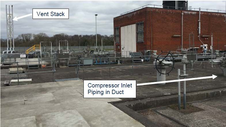
The forecast cost proposed is XXXXX (18/19 prices) in RIIO-2 for disconnection and
          decommissioning projects. This includes XXXXX for decommissioning 80 identified sites,
          assets and groups of assets and XXXXX for disconnecting five customer sites.
          For RIIO-3 we have forecast costs of XXXXX for continued disconnection and
          decommissioning activities across our network, including specific investments at Bacton
          Terminal, required following the investment included in the Bacton Terminal Redevelopment
          Justification Paper (annex A14.02). This RIIO-3 Future Decommissioning forecast is based on
          RIIO-2 anticipated spend
                     Cost Forecast (£m 18/19 prices)

                     2021/22    2022/23    2023/24     2024/25   2025/26   2026/27   2027/28   2028/29   2029/30   2030/31   Total
Customer
                                                                                                                              2.99
Disconnections
Customer Driven
                                                                                                                              9.28
Decommissioning
Decommissioning                                                                                                              81.07
Bacton RIIO-3
                                                                                                                             13.56
Decommissioning
Anticipated Future
                                                                                                                             72.31
Decommissioning
Total                  4.17      24.55      21.36       14.95     17.53     19.65     23.30     21.49     17.73     14.46    179.20
                                            82.57                                               96.64

          Delivery of our proposals will be measured via a price control deliverable as set out in annex
          A3.01

                                                                                                                      4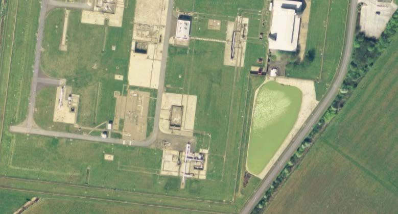
1. Introduction

1.1   This document sets out National Grid’s investment proposals for the management of
      our Redundant Assets across the RIIO-2 and RIIO-3 regulatory periods.

1.2   National Grid is requesting funding associated with removing redundant assets on the
      Gas Transmission network. A redundant asset being defined as “Any equipment or
      fixed assets which are no longer required (now or in the immediate future) for National
      Grid Gas Transmission to operate the National Transmission System (NTS)”. The
      redundancy has been driven through changes to the operation of our network driving
      redundancy in our assets and changes in specific customers activities.

1.3   Our redundant assets have no future operational requirements and have generally
      reached the end of their asset lives which constrains the potential future usages

1.4   As part of our asset health submission we have not requested allowances for the
      ongoing maintenance of the sites and assets included in this redundant asset
      investment. This is on the assumption that allowances for our preferred intervention
      are agreed. Any redundant assets funding not approved will result in increases to our
      asset health and maintenance proposals and associated spend.

2. Equipment Summary

2.1   Through reviewing our network we have identified 80 sites, groups of assets and
      single assets that we have classed as redundant. We have defined these terms as:

      Assets: A redundant asset relates to a single asset that has been identified as
      redundant to operational requirements now and in the future. For example, a redundant
      water bath heater on an offtake site (Horndon Barking Ex Canvey Island).

      Groups of assets: Redundant groups of assets relate to a partial element or function
      of a site that is no longer required for operational purposes, either constituting multiple
      assets, or where several single assets have been identified (Roxwell).

      Sites: Redundant sites are whole sites where the function of the site is no longer
      required for operational purpose and therefore all assets on the site are redundant. For
      example, Theddlethorpe Terminal where the terminal assets are no longer required to
      support a connection

2.2   These redundant sites and assets are located across the length and breadth of our
      National Transmission System (NTS) on all of our site types, such as Terminals, Multi-
      junctions, Block Valves, Compressor Sites and Above Ground Installations. Figure 1
      overleaf shows the location, geographically, of these assets across the length of our
      network, with markers signifying either redundant whole sites, groups of assets or
      single assets, including feeders.

      The redundant assets across these categories are of varying asset ages, which then
      impacts on our proposed intervention

                                                                                               5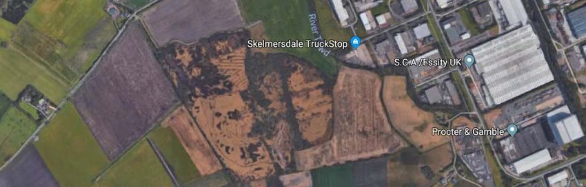
Figure 1 NTS Schematic showing location of our redundant assets, group of assets and sites,
      shown in red on the NTS map

                                                                   Blue Lines – The National
                                                                   Transmission System Pipelines

                                                                   Red Dots – Signifies a redundant site
                                                                   or a site with a single or a number of
                                                                   redundant assets.

2.3   The 80 sites, assets and groups of assets have been identified through various
      methodologies. We have reviewed projects undertaken in RIIO-1 where
      disconnections have been undertaken that we did not receive the funding to
      decommission these assets. These assets were identified as redundant to operational
      requirements and disconnected. We have interrogated our asset database (Ellipse) to
      identify assets that are redundant across our network, and we have reviewed the list
      created with our operations teams.

2.4   The table below, Table 1, provides a summary of the types of assets that have been
      identified in accordance with the categories in our Network Asset Resilience Metrics
      (NARMs) Methodology. The list is not exhaustive but has been written to demonstrate
      the varying types of primary and secondary assets (inclusive of sites) included in this
      topic:

                                                                                                    6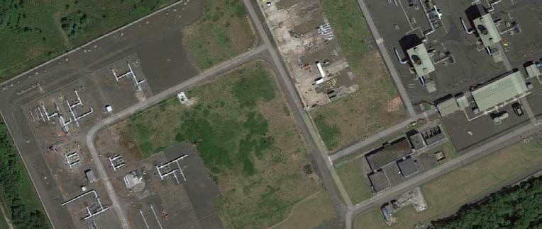
Table 1 Types of assets and sites identified as redundant
        Site/Asset Description
        Primary Asset                         Example
        Entry Point (Terminal)                Theddlethorpe Gas Terminal
        Exit Point                            Ferny Knoll AGI, Upper Neeston AGI
        Pipeline                              Feeder 14 - Austrey to Shustoke
                                              Feeder 8 - Theddlethorpe to Hatton Multijunction
                                              Feeder 17 - Theddlethorpe to Hatton
                                              Multijunction
        Secondary Asset                       Example
        Civil Assets                          Bathgate Control Building,
        (Buildings/Enclosures)                Peterborough Control Building,
                                              Peterborough Compressor Cabs
        Aftercoolers                          Wormington Aftercooler
                                              Churchover Units A and B
        Compressor Units
                                              Kirriemuir Unit D
        Preheaters                            Horndon (Barking) Water Bath Heater
                                              Huntington Diesel Storage Tank for Diesel
        Fuel Tanks and Bunds
                                              Generator

2.5    A full list of the 80 sites and assets that we have included in this investment, with the
       current operational status and Business Plan Data Table Category can be found in
       Appendix 1.

2.6    The redundant assets range from those already disconnected from the NTS and
       isolated from all sources of energy and control systems, to those which still form part
       of the operational National Transmission System.

2.7    Assets were built to a range of NTS pressures up to maximum operating pressures of
       94 bar with electrical supplies up to 400 VAC, and with electronic or hydraulic control
       systems. Some redundant assets also have mains water supplies, phone lines and
       other telemetry equipment, required to be included in the scope of the redundant
       assets project. Many of the redundant assets include asbestos that needs specialist
       management.

2.8    In Appendix 2 equipment summaries for a number of the identified redundant asset
       types are presented. These provide a description of the asset, the failure modes these
       types of assets may experience, specific to a redundant type of this asset class, and
       the consequence of failure.

Customer Disconnections

2.9    We recognise that some customers will no longer require connections to our
       network in the future, dependent on the commercial regimes and market conditions
       they operate in.

2.10   Our internal best view forecast of the economic lives of the generation assets for a
       number of our Power Station customers are that they will reach a point in RIIO-2 where
       the plants reach a point of obsolescence. Therefore, we have forecast that a
       disconnection from our network at the NTS offtake site will be required to be
       undertaken to facilitate plant run down in RIIO-2. These disconnections are in addition

                                                                                                 7
to the 80 identified redundant sites, assets and groups of assets. These sites, that
       could require a disconnection, are shown in Table 2.

       Table 2 Sites forecast to require a disconnection

2.11   Legacy Connection Agreements for each of these customers are silent on the
       responsible party for the disconnection and decommissioning costs at the offtake site.
       Therefore we are requesting an allowance to disconnect these customers from the
       NTS, which will enable the customer to undertake any work they need to on their sites
       independently. We have planned our subsequent decommissioning activities to fall into
       RIIO-3.

3. Problem Statement

3.1    Our network is getting older and is being used differently. We are faced with the
       challenge of how we best manage our redundant assets in a way that is cost
       effective, affordable and consistent with our, and the country’s, environmental and
       sustainability goals. Further details can be found in Appendix 3 Background.

3.2    Assets may become redundant for a number of reasons. The needs of stakeholders
       or individual customers might change, legislation changes may mean that assets
       cannot be used, or investments in new assets may mean that life expired assets are
       no longer required. Given the nature of our ageing network and future changes in
       how we all use energy we anticipate more work in this area will be seen in future price
       control periods.

Legislative Review

3.3    As part of the development of our plans on this topic a full review of legislation was
       undertaken to understand the specific requirements from the various acts of
       legislation. We additionally reviewed all international standards (ISO/BSI) and industry
       best practise documents. A summary of this is provided in Appendix 4 Legislation
       Review.

3.4    Having reviewed the pertinent legislation on this topic our understanding is that
       provided there are no issues of contamination or pollution there are no obligations
       mandating us to decommission our redundant assets.

3.5    This being said a number of our sites were purchased under Compulsory Purchase
       Order where planning consents can dictate the end condition of the land post
       operation, or where assets are installed on land through lease agreements which can

                                                                                             8
do the same. Where we have these requirements we shall adhere to all of our
       responsibilities.

3.6    If we did nothing we would continue to maintain assets in a manner to ensure we
       manage and mitigate the health and safety and environmental risks from these assets.

3.7    On a number of sites, such as compressor and terminal sites, we have environmental
       permits, issued by the relevant environmental regulators (Environment Agency (EA),
       Scottish Environmental Protection Agency (SEPA) or Natural Resources Wales
       (NRW)). These permits are required to be held under the UK Environmental
       Regulation’s, and detail the assets on site, such as the number of compressor units
       and place a requirement on National Grid to produce a decommissioning plan.
       We notify these regulators on our decisions to modify the number of assets held on
       these sites, such as to decommission compressor units, and submit appropriate
       decommissioning plans as required. The permits do not mandate specific intervention
       options; however they do place a requirement on us to remediate polluted land.

Network Exit Agreements/Network Entry Agreements

3.8    Our current Network Exit Agreement/Network Entry Agreements contain clauses
       which allow National Grid to recover the cost of decommissioning its assets at Network
       Entry and Exit points from the specific customer. However the legacy contracts do not
       provide clarity on this for the disconnection and decommissioning activities and such,
       where this situation has arisen, the site forms part of our funding request for this topic.

Why are we doing the work?

3.9    NTS assets have generally been constructed away from centres of population, and are
       situated in or close to a range of biodiverse ecosystems (e.g. Rivers, Estuaries,
       Farmland, Wetlands, National Parks). Our redundant assets and sites have several
       environmental hazards, which could lead to a potential for air, ground and watercourse
       contamination as well as containing asbestos. Our proposed approach to interventions
       on our redundant sites and assets will mitigate these hazards.

3.10   Even with appropriate asset management our redundant assets can also pose a safety
       risk. Our network is ageing which leads to an increased risk of loss of containment and
       other failures due to asset deterioration. This may require us to undertake more
       frequent and sometimes specialised interventions to remediate against these risks. We
       do not see this to be cost effective on assets that have no current or future operational
       requirement.

3.11   We are proposing interventions on our redundant assets now rather than later. This
       provides health and safety benefits to our employees and members of the public and
       removes the environmental risks posed by these assets. We also believe it is a fair
       treatment of costs, where costs are incurred by current consumers who have had the
       benefit from these previously operational redundant assets, rather than future
       consumers who will have had no benefit from these assets.

3.12   This position aligns with the polluter pays principle, which is a commonly accepted
       approach in the energy industry in that those who produce pollution, including those
       using systems and facilities bear the costs of managing it or decommissioning it to
       prevent future health and safety and environmental harm.

3.13   The spend is successful if we remove the safety and environmental risk posed by these
       assets and reduce ongoing maintenance costs. On operational sites the difficulty in

                                                                                                9
undertaking interventions is the close proximity of the redundant assets to operational
assets. Undertaking an intervention on these sites can have process safety risks that
need to be managed.
3.14 As part of our business plan submission we have not requested allowances for
ongoing maintenance for the identified redundant sites and assets on the assumption
that allowances are agreed for a redundant asset intervention. Should this not be
agreed there would be an increase in maintenance activities required.
RIIO-1 Performance
3.15 In our RIIO-1 baseline plan an allowance of £13.56m (18/19 prices) was proposed and
in determining their final position Ofgem made no change to this baseline proposal.
3.16 The baseline proposals included the request for allowances for twelve specific
projects, including Bathgate Compressor Station, Scunthorpe Compressor Station,
and then an amount for a number of Offtake Disconnections and Compressor Engine
decommissioning projects (to account for future decommissioning activities).
3.17 The table below, Table 3, shows our current view of performance against out
allowances.
Table 3 Allowances vs Performance
Cost (£m 18/19 prices)
2013/14 2014/15 2015/16 2016/17 2017/18 2018/19 2019/20 2020/21 Total
RIIO-1 Allowances 0.90 0.17 11.49 0.05 0.28 0.35 0.24 0.07 13.56
RRP19 Actual & Forecast 2.57 1.21 2.31 1.29 2.00 2.22 1.09 2.07 14.76
3.18 Across RIIO-1 we have incurred costs in excess of allowances for our redundant
assets intervention as we have identified and undertaken investments to make safe
redundant assets that were not identified at the point of creation of our RIIO-1
submission. This has been driven by changes in customer behaviours and better
identification of our redundant assets.
3.19 The largest increase in costs in RIIO-1 has been driven by our activities to rationalise
assets at Paul AGI, which was not included within our RIIO-1plans. The configuration
of the site meant that at the point of sale to Northern Gas Networks (NGN) in 2005 the
transfer of assets was different to that on more common offtakes, resulting in National
Grid having ownership for additional assets. Following communication with Ofgem, in
accordance with the Standard Special Condition A27 (Disposal of relevant assets and
restriction on charges over Receivables), we agreed with Ofgem and NGN a
rationalisation approach for the site, which had significant asset health issues.
3.20 This improved the reliability of the network and removed safety risks associated with
poor condition assets whilst enabling the proposed new Feeder 9 pipeline to enter
Paull AGI in a more cost efficient location.
3.21 Across RIIO-1 redundant assets have also been created following changes in
customers behaviours, both individual customers affecting offtake sites and changes
to supply and demand patterns across our network affecting AGIs, Compressor
Stations & Multi-junctions.
103.22 In preparing for our RIIO-2 business plan we have undertaken an in depth analysis of
our assets base for this topic. This has resulted in the identification of redundant assets
across our network driving the rise in projects, and therefore an increased investment
proposals compared to RIIO-1.
Real Life Examples of Problem
3.23 This section of the report provides four real life examples of redundant assets. The
drivers for redundancy are varied, as shown in these examples, with reasoning
based on operational, customer and third party requirements.
Example 1 - Bathgate Control Building (xxxxxx)
3.24 Bathgate Compressor Station was located in Scotland at the junction of Feeder 10,
11 and 12.
3.25 Bathgate Compressor Station originally contained four Avon Gas Turbine units.
However to reduce emissions and increase network capacity a decision was made to
construct Avonbridge compressor station. This occurred in 2003, with the new site
neighbouring the Bathgate site.
Figure 2 Location of Bathgate NTS site
3.26 Following acceptance of the new Avonbridge compressor station the Bathgate
Compressor station, was isolated and decommissioned as mandated by the SEPA
licence condition “As from 1st July 2009, Gas Turbine Units B and C shall not be
operated” .
3.27 The scope of the decommissioning project excluded the main control building, which
housed an administration building, workshop and standby generator room. At the time
of the project the strategy for the office was for continued use as office
accommodation and for the workshop to be used to temporarily house the spares
from the decommissioning project.
3.28 The control building is located on the southern part of the site, in close proximity to
the Avonbridge site as shown in the figure overleaf.
11Figure 3 Bathgate/Avonbridge site layout
Avonbridge
Bathgate
Bathgate Control Building
3.29 In the intervening years, the control building has been vacated following the
procurement of alternative office accommodation. Power, water and telecoms
services have been disconnected, with the building structure remaining in situ.
3.30 The building is clad in steel panels. As can be seen from the photos below, Figure 4,
these material are susceptible to corrosion & degradation due to environmental
conditions which can and have manifested as failures to the cladding. Additionally the
building has a flat roof for which the membrane deteriorates over time and with
environmental exposure. This has resulted in water ingress resulting in rotting.
Figure 4 Bathgate Control Building
3.31 Our management study for the building states that Asbestos is present in the control
building and therefore doing nothing increases the risk of further deterioration of the
building fabric resulting in ground, air and water contamination from this hazardous
material and non compliance with Health & Safety legislation.
3.32 The problem we are faced with is how best to manage the risk posed by this redundant
asset with an intervention methodology that mitigates the health and safety,
environmental and financial risks associated with ongoing management of the building
whilst maintaining our statutory obligations to health and safety in the workplace and
also being the most cost effective method.
3.33 Our proposal is to decommission this building back to ground level, removing all
asbestos. This will mitigate the risks posed by this building that provides no operational
benefit to our network. We will continue to own the land due to the proximity of adjacent
operational NTS assets.
12Example 2 - Theddlethorpe Terminal, Multijunction and Feeder assets (xxxxxx)
3.34 Theddlethorpe gas terminal is on the east coast of the UK as indicated in Figure 5.
The beach terminal is owned and operated by ConocoPhillips, receiving UKCS gas
from fields in the Southern North Sea. National Grid owns and operates the entry
terminal which facilitates gas flow from the ConocoPhilips site on to the NTS. The
terminal was commissioned in 1972, originally designed to accommodate significant
flows; in excess of 85 mcm/day. National Grid is a significant land owner at this locality
owning the land for our own terminal, ConocoPhillips site and an area of land current
leased to agricultural tenants.
Figure 5 Location of Theddlethorpe Terminal
3.35 The National Transmission System (NTS) entry terminal site is connected to a
multijunction site “Theddlethorpe Multijunction (1811)” and the wider Transmission
System through two feeders, Feeder 17 and Feeder 8, which connect to Hatton
Multijunction. Along the length of Feeder 17 are two block valve sites, Goulceby and
Little Cawthorpe. A site aerial view is shown in Figure 6 below, where the blue boxes
represent the multijunction assets, the red lines representing the feeder assets.
Figure 6 Theddlethorpe Terminal site plan
Location of the below ground site
ring main
Blue Boxes
Areas of the site designated as Multi-
Feeder 17 Theddlethorpe junctions, where Feeders 8 and 17
to Hatton Multijunction connect to the Terminal assets
Feeder 8 Theddlethorpe to
Hatton Multijunction
133.36 xxxxxxxxxxxxxxxxxxxxxxxxxxxxxxxxxxxxxxxxxxxxxxxxxxxxxxxxxxxxxxxxxxxxxxxxxxx
xxxxxxxxxxxxxxxxxxxxxxxxxxxxxxxxxxxxxxxxxxxxxxxxxxxxxxxxxxxxxxxxxxxxxxxxxxx
xxxxxxxxxxxxxxxxxxxxxxxxxxxxxxxxxxxxxxxxxxxxxxxxxxxxxxxxxxxxxxxxxxxxxxxxxxx
xxxxxxxxxxxxxxxxxx
3.37 The site contains various different asset types and classes including various buildings
(including the control building), above and below ground pipework, scrubbers, meters
pig traps, electrical infrastructure including standby generators, preheaters etc.
Figure 7 shows photos of the site, demonstrating the range of assets.
Figure 7 Theddlethorpe Site Photos
3.38 This investment will enable us to most appropriately manage a site whose function is
no longer required. The site contains various asset types of varying ages, some of
which are obsolete, and which have multiple failure types and failure rates. We need
to ensure that our investment proposal addresses the requirements from the site, is
cost effective, sufficiently manages the health and safety and environmental risks, and
ensures compliance with legislative requirements and the relevant regulatory bodies.
3.39 In addition the terminal site, National Grid owns a significant area of land,
xxxxxxxxxxxxxxxxxxxxxxxxxxxxxxxxxxxxxxxxxxxxxxxxxxxxxxxxxxxxxxxxxxxxxxxxxxx
xxxxxxxxxxxxxxxxxxx.
143.40 This land ownership is shown in Figure 8 below, with the area demarcated within the
green boundary being the land owned by National Grid. Our strategy has considered
not just future requirements for the National Grid terminal site but also the
ConocoPhilips site.
Figure 8 Theddlethorpe National Grid Land ownership
]]
3.41 To develop our strategy for the site we have undertaken a robust process of external
engagement, mainly in the form of 1-1 sessions with relevant stakeholder and these
included:
• xxxxxxxxxxxxxxxxxxxx
• xxxxxxxxxxxxxxxxxxxxxxxxxxxxxxxxxxxxxxxxxxxxxxxxxxxxxxxxxxxxx
• xxxxxxxxxxxxxxx
3.42 Our engagement with xxxxxxxxxxxxxxxxxxxxxxxxxxxxxxxxxxxxxxxxxxxxxxxxxx
enabled us to listen and understand what was important to them, this being ensuring
the site provides an economic benefit to the local area in the future, through promoting
jobs. We are keen to ensure synergies between our strategy for the site and the
councils local strategy.
3.43 xxxxxxxxxx commissioned their own report around future opportunities for the site, to
ensure they are in the best position to help facilitate any changes in operation of the
site. Their preference would be to continue usage for an energy purpose. This proposal
would require the removal of all our existing assets at the site. The council of supportive
of our plans for the Theddlethorpe Terminal site included within this submission.
3.44 The National Grid land at Theddlethorpe is a potential location for the export of CO2
for Carbon sequestration in the North Sea as part of a Carbon Capture Usage and
Storage (CCUS) scheme or a location for the production of Hydrogen. These scheme
and others are at a very early conceptual phase and require significant work to develop.
3.45 However these schemes would not only enable the continued use of the site for energy
purposes but also enable the repurposing of existing feeder assets for these alternative
innovative purposes, which may bring additional consumer benefits in the longer term.
15Our current business plan includes the provision to undertake a feasibility study in
RIIO-2 to consider these future activities for the site. This is included within the chapter:
“I want you to facilitate the whole energy system of the future”.
3.46 As part of the general engagement we undertook during the development of our
business plan we held a number of workshops, regional events and webinars where
we engaged with our stakeholders on the redundant asset’s topic. In our engagement
with our stakeholders we specifically asked questions in relation to the repurposing of
our feeder assets. Some of the specific feedback received is shown below:
“An alternative would be to explore changes of use i.e. the transport of other products
in redundant parts of the network.”
“National Grid should explore and understand more fully alternative uses and
management of risk in the interim, which could then allow for opportunities.”
“An alternative would be to leave buried pipelines and take out compressors. This is
because of the fact pipelines might have to be reused, and that the visual impact of
compressors may effect National Grid's reputation.”
A full summary of our engagement can be found in the appendix A16.07 Demolition
Engagement Report.
3.47 We agree with these statements and therefore our proposal for RIIO-2 is to purge
feeder 17 and feeder 8 from Theddlethorpe to Hatton Multijunction to Nitrogen with a
view of the repurpose opportunities referenced earlier.
3.48 Our breakdown of costs for this project is as per Table 4 below. The feeder costs
shown reflect the disconnection and Nitrogen filling of both pipelines to enable us to
consider future opportunities before more permanent decommissioning is
undertaken. Costs at Theddlethorpe and Hatton Multijunction reflect a scope
including the decommissioning of our assets at these sites associated with the flow
line from Theddlethorpe.
Table 4 Theddlethorpe and connected assets decommissioning costs
£m 18/19 prices
Theddlethorpe Terminal and Multijunction
Goulceby Block Valve
Little Cawthorpe Block Valve
Feeder 17 Theddlethorpe – Hatton Multijunction
Feeder 8 Theddlethorpe – Hatton Multijunction
Rationalisation of Hatton Multijunction,
decommissioning assets in relation to Feeder 8
and 17 connections
Total
3.49 xxxxxxxxxxxxxxxxxxxxxxxxxxxxxxxxxxxxxxxxxxxxxxxxxxxxxxxxxxxxxxxxxxxxxxxxxxx
xxxxxxxxxxxxxxxxxxxxxxxxxxxxxxxxxxxxxxxxxxxxxxxxxxxxxxxxxxxxxxxxxxxxxxxxxxx
xxxxxxxxxxxxxxxxxxxxxxxxxxxxxxxxxxxxxxxxxxxxxxxxxxxxxxxxxxxxxxxxxxxxxxxxxxx
xxxxxxxxxxxxxxxxxxxxxxxxxxxxxxxxxxxxxxxxxxxxxxxxxxxxxxxxxxxxxxxxxxxxxxxxxxx
xxxxxxxxxxxxxxxxxxxxxxxxxxxxxxxxxxxxxxxxxxxxxxxxxxxxxxxxxxxxxxxxxxxxxxxxxxx
xxxxxxxxxxxxxxxxxxxxxxxxxxxxxxxxxxxxxxxxxxxxxxxxxxxxxxxxxxxxxxxxxxxxxxxxxxx
xxxxxxxxxxxxxxxxxxxxxxxxxxxxxxxxxxxxxxxxxxxxxxxxxxxxxxxxxxxxxxxxxxxxxxxxxxx
16Xxxxxxxxxxxxxxxxxxxxxxxxxxxxxxxxxxxxxxxxxxxxxxxxxxxxxxxxxxxxxxxxxxxxxxxxxxx
xxxxxxxxxxxxxxxxxxxxxxxxxxxxxxxxxxxxxxxxxxxxxxxxx
xxxxxxxxxxxxxxxxxxxxxxxxxxxxxxxxxxxxxxxxxxxxxxxxxxxxxxxxxxxxxxxxxxxxxxxxxxx
xxxxxxxxxxxxxxxxxxxxxxxxxxxxxxxxxxxxxxxxxxxxxxxxxxxxxxxxxxxxxxxxxxxxxxxxxxx
17Example 3 - Ferny Knoll AGI (xxxxxx)
3.50 Ferny Knoll AGI was the offtake point for an Industrial Customer AM Paper, a paper
mill. The AGI is situated on a 42-inch stretch of Feeder 15, north and south of Crank
Block Valve and Burscough Multijunction Pig Trap respectively, as shown on the NTS
Schematic below (Figure 9).
Figure 9 Location of Ferny Knoll Offtake
3.51 The National Grid AGI site is located circa 1.6km away from the Paper Mill, as the crow
flies, as shown below with AM Paper owning the pipeline between the NTS offtake site
and customer site.
3.52 In August 1999 AM Paper was acquired by SCA Group with the paper mill
mothballed in 2008.
3.53 The pipeline from Ferny Knoll AGI to the AM Paper site was disconnected from the
National Grid Ferny Knoll AGI in February 2009, with a dome end installed outside
the perimeter of the National Grid AGI site, as shown in Figure 10 overleaf.
18Figure 10 Ferny Knoll Engineering Line Diagram showing disconnection
3.54 At the time of the disconnection we reviewed the Network Exit Agreement (NExA) in
regards to the ability to recover costs from the customer for this activity. The NExA
does not enable us to recover the isolation, disconnection or decommissioning costs
from the customer.
3.55 The problem the investment seeks to solve is how we most appropriately manage a
site, whose function is no longer required for our customer’s usage of the NTS, for the
lowest total cost. It also seeks to mitigate future obsolescence-related risks on assets
that have no current or future operational requirement, ensuring that customers who
have had the benefit of these assets incur the cost for the end of life intervention.
The site is shown in Figure 11 below.
Figure 11 Ferny Knoll Site
3.56 Our baseline proposal for RIIO-2 includes the full decommissioning of the Ferny
Knoll AGI site from the National Transmission System, returning the site to
brownfield condition. This mitigates the health and safety and environmental risk
from these assets, which have no future operational requirements.
19Example 4 – Warrington Compressor Units A and B and associated infrastructure
(xxxxxx)
3.57 Warrington Compressor Station is connected to Feeder 15 and Feeder 21, located
2 km east of the town of Warrington. The location on the NTS is shown in Figure 12,
below.
Figure 12 Location of Warrington Station
3.58 The station was constructed in 1984 and has two identical gas turbine driven
compressor units designed to operate independently of each other.The station was
primarily designed to facilitate entry into our network at Barrow and St Fergus
by moving large volumes of gas into the south. Warrington’s use has reduced
significantly over the last five years, with the two compressor units being run for
a combined average of 34 hours per year.
3.59 The two units are not compliant with the Industrial Emissions Directive - Large
Combustion Plant (IED-LCP). The IED set the minimum requirements for emissions of
Nitrogen Oxide (NOx) and Carbon monoxide (CO) to the environment from the
combustion of natural gas, with all non-compliant machines required to cease
operation by 31 December 2023.
3.60 Both units at Warrington are affected and therefore we started operating them on 500-
hour Emergency Use Derogations (EUD) in order to comply with the LCP element of
the legislation. However based on the current Future Energy Scenarios (FES),
Warrington is no longer required to support the entry flows it was designed for.
Although there is the potential for future user signals to require additional west coast
compression, there is no certainty over when these signals will be received, if at all.
3.61 The problem that the investment seeks to solve is to mitigate current and future
obsolescence, safety and environmental related risks on assets that have no current
or future operational requirement, ensuring that customers who have had the benefit
of these assets incur the cost for the end of life intervention.
203.62 The consequence of doing nothing would result in a requirement to maintain the
existing assets in line with the current statutory inspections i.e. Pressure Vessel and
Pressure System Inspection (PSSR) and Dangerous Substance and Explosive
Atmosphere Regulations 2002 (DSEAR). We have forecast this to be £80k per annum,
broken down as shown below:
Table 5 Asset Health and Opex Costs
Activity Cost (18/19)
Asset Health £60k/yr
PSSR Activities £20k/yr
Total £80k/yr
3.63 With the assets still pressurised at NTS pressure the consequence of doing nothing
could also manifest as a requirement to undertake interventions to mitigate health and
safety and environmental risks driven by asset obsolescence issues at a site which will
continue to be used by operations staff.
3.64 Based on this analysis our proposal for RIIO-2 is to disconnect and decommission the
compressor station from the NTS. As part of the development of our plans for the
compressor station we have looked to determine future uses for the site.
3.65 Our current strategy for the site is to retain the use of the site as an operational base
and stores for our operational teams.
3.66 Our decommissioning scope of works includes the decommissioning of one of the
compressor units and associated station pipework, including pressure reduction
installation. However we are proposing to move one of the existing RB211 compressor
units to another compressor site, to reuse this power turbine for future operational use.
3.67 We also propose to undertake modifications of the AGI to operate independently of the
station. It is proposed that the control building and cab buildings will be retained for
future use. Figure 13 highlights the types of assets identified as redundant, including
the vent stack, compressor units, pits containing compressor inlet pipework, the
pressure reduction area containing scrubbers, filters and a condensate tank and the
fire pond.
Figure 13 Warrington Redundant Assets
213.68 The decommissioning proposal is subject to employee and trade union consultation
22Example 5 – Moffat Compressor Station (xxxxxx)
3.69 Moffat Compressor Station is connected to Feeder 11 and Feeder 12, located 6km to
the south of the town of Moffat. The location on the NTS is shown in Figure 14,
below.
Figure 14 Location of Moffat Compressor Station
3.70 The station was constructed in 1980 and has two identical gas turbine driven
compressor units designed to operate independently of each other. The station was
primarily designed to provide network compression to move gas from Scotland to the
south. The run hours on both units at Moffat have significantly reduced since
2006/07. This reduction in compression requirements aligns with the fall in flows
coming onto the National Transmission System (NTS) via the St Fergus Terminal in
Scotland.
3.71 The units are now primarily being used:
• To provide occasional network resilience to Aberdeen, Kirriemuir and Avonbridge
• To provide occasional resilience to Carnforth and Nether Kellet
• To support entry flows from St Fergus.
3.72 Our current cost forecast for asset health activities should no redundant assets
intervention be made is XXXXX over a 10 year RIIO-2 and RIIO-3 period is shown in
Table 6 below.
23Table 6 RIIO-2 & RIIO-3 Forecast Asset Health Costs
RIIO-2 & RIIO-3
Forecast Asset
Theme Health Costs
£m (18/19)
Cabs
Compressor
Plant & Equipment
Valves
Civils
Electrical
Total
3.73 However we do not believe these units are required in the longer term to meet our
network capability needs. As set out in our Fleet Strategy Annex A11.04, we do not
believe continuing operation of the units to be the most cost effective solution, given
the current user signals for west coast compression, forecast run hours, and forecast
asset health costs. Therefore the decision has been made to disconnect and
decommission the compressor station in RIIO-2.
3.74 Our decommissioning scope of works includes the decommissioning the compressor
site, including the compressor units and associated station pipework (pressure
reduction installation, filters and scrubbers). Included within this is a proposal to
retain a unit from the site as a fleet spare.
3.75 Other assets such as civil assets (buildings, fences etc), Electrical assets such as
generators, telemetry etc will be decommissioning and the site returned back to
ground level. Modifications will be undertaken to separate the compressor station
pipework from the pipework feeding Moffat AGI, which is located adjacent to the
compressor site, but supplied from the compressor site. This site is used by our
customer, for the Moffat Interconnector and will continue as a live site going forward.
3.76 The decommissioning proposal at the site is subject to employee and trade union
consultation.
Spend Boundaries
3.77 The spend boundaries will differ on each individual decommissioning project. This is
due to the varying requirements for NTS disconnections, disconnections of SCADA
and control systems and the varying scope and extent of the decommissioning
intervention activities on each project.
3.78 The decommissioning projects are currently at the end of stage 4.0 ‘Need Case’ of our
Network Development Process (ND500), shown below. The ND500 stage gates
ensure minimum requirements are met for each phase and are shown in the figure
below. Stage 4.0 is used to establish the need to do something and the scope of this
need.
244.0 4.1 4.2 4.3 4.4 4.5
3.79 In general the costs included in this investment are to progress the projects through
4.1 Establish Portfolio to 4.5 Review and Close Project for the decommissioning of our
redundant sites and assets. These stages includes the following activities:
• Undertaking Front End Engineering Design (FEED) activities including the
development of scheme designs, including locations of isolations and
disconnections, and the development of decommissioning plans.
• Isolation and disconnection of redundant assets from all sources of energy and
services. Inc Control Systems, NTS Pressure Gas, HV/LV Electricity
• Decommissioning of these assets back to plinth or ground level.
• Updates to all relevant site drawings and records
3.80 For a number of investments, costs are included for additional activities to support
the scope of the decommissioning. Examples of activities include dome ends and
pipeline loops for our feeder assets, or reconfiguration of control systems. These
investments are required to ensure the safety and integrity of our operational
National Transmission System are not impacted.
4. Probability of Failure
4.1 Our redundant assets are those assets that are no longer required (now or in the
immediate future) for National Grid to operate the NTS. Therefore the failure is different
to that of our operational assets, where asset failures could result in direct impacts to
the operation of our network.
4.2 Depending on the type of asset the probability of failure will also be different to that of
an operational asset, e.g. where disconnections result in assets operating at
atmospheric pressure rather than to NTS pressure, the stresses placed on the assets
are lower resulting in less strain fatigue cycling. However the probability of failure could
be higher or occur more quickly because of the age and condition of these assets.
Buildings and Enclosures
4.3 However there are some assets where the probability of failure is consistent whether
the asset is redundant or operational. An example of this are Buildings and Enclosures.
4.4 The chart below shows the condition deterioration curve for operational buildings and
enclosure assets. The model uses the parameters derived within the development of
our NARMS methodology showing how the asset degrades over time from Asset
Health Condition Grade 1 to Grade 5. Grade 5 is reached sometime after 35 years
25from new. The modelled asset life is plotted on the x-axis with condition grade shown
on the y-axis.
4.5 The condition grade is used to explain the current condition of the asset at a specific
asset life, this driving the interventions that may be required to undertaken across the
lifecycle of the asset. Asset Health Grade 5 is deemed to be a building at the end of its
serviceable life.
4.6 For redundant buildings and enclosures the probability of failure is forecast to be
similar to that of operational facilities. However without heat or power within the facility
and with obsolescence-related material deterioration, a sharper curve could also be
experienced, resulted in an earlier building fabric failure, reaching AH5 state earlier,
resulting in a requirement to intervene to mitigate health and safety issues.
4.7 Buildings towards the end of their operational life may also experience settlement
issues, which can manifest as significant cracks in supporting structures resulting in
buildings being abandoned, requiring a redundant assets intervention. This can also
accelerate the deterioration of the condition of the building.
4.8 In Appendix 2 a number of equipment summaries have been produced. These
explain the failure modes for a number of the types of our redundant assets, and the
potential consequences of failure.
26Risk Prioritisation
4.9 With the constraints of our investment planning process we have implemented an
approach to prioritise our treatment of redundant assets across the RIIO-2 period
based on a risk score.
4.10 Our prioritisation methodology considers a number of factors such as environmental
impact, asset condition, health and safety metrics (such as the risk to our operational
personnel) and societal metrics (such as the proximity to centres of population). Within
this methodology we utilise a probability of failure metric to assess the condition of the
equipment. This being the failure rates per annum.
4.11 A full list of metrics and the explanation of these are shown in Table 7, below.
Table 7 Prioritisation Tool Metrics
Metric Explanation
Environmental Risks Asbestos, Naturally Occurring Radioactive Material (NORM) and
Covering Asbestos, Naturally Contaminants such as oil can cause adverse impacts on the environment, such
Occurring Radioactive Material as to soil and water courses. Assets containing these materials are prioritised
(NORM) and Contaminants over those that do not.
Societal Risks Sites closer to centres of population are prioritised as these are more likely to
Proximity to centres of be impacted by redundant assets.
population
Societal Risks If the site or part of the site becomes available through removing redundant
Potential to re-use site assets and can be reused for alternative uses it will be scored higher.
Societal/Environmental risks The makeup of the surrounding land around the redundant asset or redundant
Makeup of surrounding land site.
Sites within agricultural land and green space are prioritised over industrial and
hard standing areas
Site Manned/Unmanned Unmanned sites are scored higher than manned sites due to potential changes
in asset state/condition not being identified as quickly as on manned sites.
Condition The assessment of the condition is based on the failure rates per annum, which
Assessment/Probability of is the likelihood of that asset deteriorating to an extent it causes asset failure.
Failure The higher the chance of asset failure the higher priority given.
Assets have been split between Civil, Rotating, Mechanical and Electrical.
Data has been used from Network Asset Resilience Metrics (NARMs) Service
Risk Framework
Contains Energy Assets that are isolated are ranked lower than assets containing any forms of
(Process Fluids, Springs, energy. These forms of energy are ranked from low to high based on the
Hydraulics etc.) assumed potential for harm.
Risk to Personnel on site Risk to Personnel on site is determined through using NARMs Service Risk
Framework values
Assets have been split between Civil, Rotating, Mechanical and Electrical due
to the varying potential for harm.
4.11 In our workload forecast we have prioritised projects that generated a higher risk
score, whilst also aligning this work to available network outages where these are
required.
27Probability of Failure Data Assurance
4.12 In determining our prioritisation of redundant assets we have utilised applicable
measures within our existing Network Asset Resilience Metric (NARM) Service Risk
Framework. The Service Risk Framework was originally submitted for public
consultation in April 2018, with three generally favourable responses received in May
2018. This been an input into the process for the determination of a risk value for each
of the redundant assets and sites. Further details on this are included in Appendix 5.
5. Consequence of Failure
5.1 The consequence of an asset failure varies depending on the type of asset that
experiences the failure, the pressure rating that it is operating in and, for redundant
assets, the state of the disconnection on the asset.
5.2 For operational assets the consequence of failure is as per those consequences shown
in each of the individual Asset Health Engineering Justification Reports. Although each
type of asset has its own consequence of failure there are a number of service risk
consequences. These being:
Health and Safety risk – This being the risk of harm from National Grid assets to our
employees and the general public. This also includes the direct impact of ensuring
compliance with the legislation relating to health and safety.
Environmental risk - This being associated with ensuring compliance with
environmental legislation and any environmental incidents caused by our assets.
Availability and Reliability risk – This being associated with the potential outages
caused from the loss of an asset on the operation of the NTS.
Societal risk – This being the impact on the wider society of our assets and can
broadly be split into categories such as the operational consequence, the safety impact
of failure and the environmental impact, with the consequences of these factors
differing depending on the type of asset.
Financial risk – This being mostly associated with the costs of maintaining the asset
at the current level of risk.
5.3 For redundant assets the consequence of failure can broadly be split into the same
categories, with the exception of the Availability and Reliability risk. For our
disconnected redundant assets the consequence of failure in relation to the
impact on the operation of our network is less relevant.
5.4 By their nature redundant assets are not part of the operational transmission system
and therefore there are no direct risks on security of supply. However, there is a risk
that structural integrity failures of these redundant assets can result in damage to
operational assets, and hence we need to ensure we manage this risk e.g. failing
structures due to environmental conditions such as wind.
5.5 In Appendix 2 a number of equipment summaries have been prepared for the types of
assets that have been identified as redundant. Within these equipment summaries the
consequences of failure have been shown, assuming a redundant type of these assets.
285.6 There are a number of similar consequences across all of the varying types of
redundant assets, with these summarised below:
Health and Safety Consequences – Asset deterioration due to obsolescence and
environmental conditions has the potential to cause harm to National Grid operatives
on the site and members of the public externally to our sites. Some of our assets
contain hazardous materials, such as Asbestos. This was widely used at the time of
the construction of many of our buildings, and therefore needs sufficient management
to mitigate the risk to our operatives.Failures of buildings and equipment from falling
masonry and equipment have the potential to result in harm, to both people and to any
adjacent operational assets.
Environmental Consequences – The potential for ground and watercourse
contamination from;
• the degradation of assets due to obsolescence issues, such as from the
corrosion of our redundant assets,
• from the deterioration of Asbestos building materials, or
• oil or operational fluid carrying equipment.
Enforcement Action – One consequence of asset deterioration could be enforcement
action by any one of our regulators, including the Health and Safety Executive (HSE),
Environmental Agency (EA), Scottish Environmental Protection Agency (SPEA) and
Natural Resources Wales.
Financial Consequences – If asset integrity failures do occur there could be the
requirement to undertake further interventions, which would not present value for
money for assets that provide no operational benefit to National Grid, however would
be undertaken out of necessity. Additionally any enforcement action from the
regulatory bodies could result in financial penalties. We also believe our focus should
be on maintaining our operational assets vs our redundant assets.
5.7 In our assessment of our redundant assets we have only reviewed assets and sites
that are currently redundant and have no forecast future use, rather than assets that
may become redundant in the future due to changes in supply and demand and
therefore the level of network flexibility required.
29You can also read