An EMD-LSTM Deep Learning Method for Aircraft Hydraulic System Fault Diagnosis under Different Environmental Noises
←
→
Page content transcription
If your browser does not render page correctly, please read the page content below
aerospace
Article
An EMD-LSTM Deep Learning Method for Aircraft Hydraulic
System Fault Diagnosis under Different Environmental Noises
Kenan Shen 1            and Dongbiao Zhao 2, *

                                         1   College of Automation Engineering, Nanjing University of Aeronautics and Astronautics,
                                             Nanjing 210016, China
                                         2   College of Mechanical and Electrical Engineering, Nanjing University of Aeronautics and Astronautics,
                                             Nanjing 210016, China
                                         *   Correspondence: zdbmezdbme@nuaa.edu.cn

                                         Abstract: Aircraft hydraulic fault diagnosis is an important technique in aircraft systems, as the
                                         hydraulic system is one of the key components of an aircraft. In aircraft hydraulic system fault
                                         diagnosis, complex environmental noises will lead to inaccurate results. To address the above
                                         problem, hydraulic system fault detection methods should be capable of noise resistance. Previous
                                         research has mainly focused on noise-free conditions and many effective approaches have been
                                         proposed; however, in real-world aircraft flying conditions, the aircraft hydraulic system often has
                                         strong and complex noises. The methods proposed may not have good fault detection results in
                                         such a noisy environment. According to the situation, this work focuses on aircraft hydraulic system
                                         fault classification under the influence of a hydraulic working environment with Gaussian white
                                         noise. In order to eliminate the noise interference and adapt to the actual noisy environment, a new
                                         aircraft hydraulic fault diagnostic method based on empirical mode deposition (EMD) and long
                                         short-term memory (LSTM) is presented. First, the hydraulic system is constructed by AMESIM.
                                         One normal state and five fault states are considered in this paper. Eight-channel signals of different
                                         states are collected for network training and testing. Second, the EMD method is used to obtain the
                                         different intrinsic mode functions (IMFs) of the signals. Third, principal component analysis (PCA) is
                                         used to obtain the main component of the IMFs. Fourth, three different LSTM methods are chosen
                                         to compare and the best structure that is chosen is the gate recurrent unit (GRU). After that, the
Citation: Shen, K.; Zhao, D. An          network parameters are optimized. The results under different noise environments are given. Then,
EMD-LSTM Deep Learning Method            a comparison between the EMD-GRU with several different machine learning methods is considered,
for Aircraft Hydraulic System Fault
                                         and the result shows that the method in this paper has a better anti-noise effect. Therefore, the
Diagnosis under Different
                                         proposed method is demonstrated to have a strong ability of fault diagnosis and classification under
Environmental Noises. Aerospace
                                         the working noises based on the simulation results.
2023, 10, 55. https://doi.org/
10.3390/aerospace10010055
                                         Keywords: aircraft hydraulic system; fault diagnosis; EMD; LSTM; anti-noise
Academic Editor: Felipe A. C. Viana

Received: 28 November 2022
Revised: 18 December 2022
Accepted: 20 December 2022
                                         1. Introduction
Published: 5 January 2023                     The hydraulic system is an important part of an aircraft, which is the key to ensuring
                                         the safety of both the aircraft and its passengers. Aircraft hydraulic systems account for a
                                         large proportion of aircraft maintenance work, the failures of aircraft hydraulic systems
                                         make up about 30% of total mechanical failures, and their maintenance accounts for one-
Copyright: © 2023 by the authors.        third of the total mechanical maintenance [1].
Licensee MDPI, Basel, Switzerland.
                                              Therefore, the hydraulic system has a crucial impact on the reliability of the whole
This article is an open access article
                                         aircraft system, and effective fault diagnostic methods should be presented to ensure
distributed under the terms and
                                         the safe operation of the aircraft. In order to ensure the safety of the hydraulic system,
conditions of the Creative Commons
                                         numerous fault diagnostic methods are proposed. Early research can be divided into two
Attribution (CC BY) license (https://
                                         categories, that is, experience-based diagnostic methods [2–4] and model-based diagnostic
creativecommons.org/licenses/by/
4.0/).
                                         methods [5,6]. However, with these methods, it is hard to distinguish all the fault types in

Aerospace 2023, 10, 55. https://doi.org/10.3390/aerospace10010055                                          https://www.mdpi.com/journal/aerospace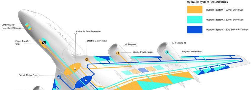
Aerospace 2023, 10, 55                                                                                           2 of 26

                         a hydraulic system, and it is difficult to establish a model because of the complexity of the
                         aircraft hydraulic system. Therefore, a lot of advanced approaches to deep-learning-based
                         fault diagnosis and feature extraction have been proposed [7–10] in recent years. Among
                         these methods, the LSTM-based methods have a better processing ability to deal with
                         timing signals.
                              Long short-term memory (LSTM) neural network is an improved recurrent neural
                         network (RNN) structure that can effectively process time sequence data [11]. It is mainly
                         used to solve the problem of gradient disappearance and gradient explosion during the long
                         sequence training process in RNN. A LSTM can adaptively learn the dynamic information
                         of time sequences by non-linear gating units that regulate the information into and out of
                         the memory cells of the LSTM. At present, this method is widely used in the field of image
                         generation, classification, and feature extraction [12–14]. In recent years, LSTM has been
                         applied in the field of fault diagnosis since this method combines feature extraction and
                         classifier design into one neural network. Cabrera et al. propose a method that combines
                         the bayesian approach and time series dimensionality reduction to build an LSTM model
                         to evaluate the faults of a reciprocating compressor. Their simulation results show that
                         the accuracy of this method is higher than the other machine learning algorithms in the
                         paper [15]. Khorram et al. present a method using convolutional neural networks (CNNs)
                         to improve an LSTM model. When using CNNs as the feature extraction layer and using
                         LSTM as the classification layer to deal with the fault diagnosis in a bearing, the simulation
                         results show that their method is better than the CNN method [16]. Ravikumar et al.
                         propose a gearbox fault diagnostic method based on multi-scale deep residual learning
                         and a stacked LSTM model, and the simulation results show that their method has the best
                         accuracy and shortest testing time [17]. In addition, there are several other research studies
                         on the application of the fault diagnostic method of LSTM [18–21].
                              The proposed methods all have good fault diagnostic results. However, these methods
                         are not used in aircraft hydraulic systems. In a real aircraft hydraulic system working
                         environment, noises exist on a wide frequency range, which may result in violent changes,
                         and this situation makes it difficult to conduct fault diagnosis [22,23]. Therefore, the
                         proposed methods cannot be effective in such a noisy environment. Empirical mode
                         deposition (EMD) is a widely used time–frequency signal deposition method that is useful
                         for analyzing complex and nonlinear signals and has been widely applied to the field
                         of fault diagnosis in a noisy environment [24–27]. During EMD, a number of complete
                         components called intrinsic mode functions (IMFs) are adaptively obtained. The IMFs
                         contain the feature information of the original signals, and will not cover the information
                         under the noise as time serial signals. Therefore, this method can reduce the effect of noise
                         on the result of fault diagnosis.
                              To address the above problems, a model based on EMD and an LSTM network (EMD-
                         LSTM) is proposed in this paper. The remainder of this paper is organized as follows:
                         Section 2 defines the aircraft hydraulic system and presents how an AMESIM aircraft
                         hydraulic system was built; six states were considered and eight different channel signals of
                         the states were collected. In Section 3, the EMD-LSTM method is proposed; three different
                         inner structures of LSTM were considered, the main structure of LSTM was designed,
                         and the parameters and the flow chart of the EMD-LSTM are presented. In Section 4,
                         the simulation results of the three LSTM networks are presented. The inner structure of
                         GRU was the best. Then, the structure and parameters of the EMD-GRU were optimized.
                         Different SNR Gaussian white noises were added to the eight-channel signals to simulate
                         environmental noises. The EMD-GRU method was used for fault diagnosis under different
                         environmental noises. The simulation results show that this method can resist 40 dB noises.
                         Finally, we compared this method with several other machine learning algorithms. The
                         results show that the method in this article has better accuracy in high-noise environments.
                         Section 5 concludes this research.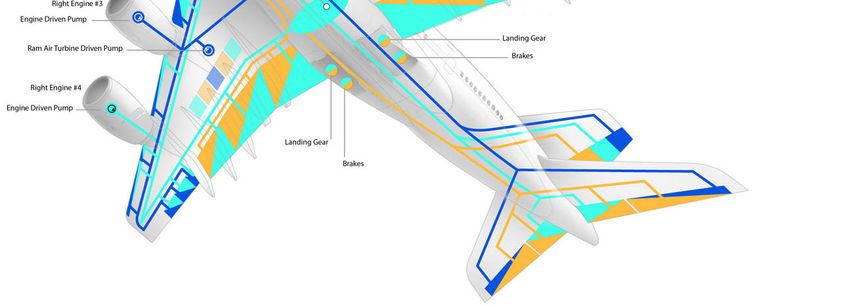
Aerospace 2023, 10, x FOR PEER REVIEW 3 of 27
Aerospace 2023, 10, 55 3 of 26
2. Aircraft Hydraulic System Model Building and Data Collection
2. Aircraft Hydraulic System Model Building and Data Collection
2.1. Aircraft Hydraulic System Definition and AMESIM Model Build
2.1. Aircraft Hydraulic System Definition and AMESIM Model Build
The hydraulic system is one of the core systems of an aircraft flight, with the functions
The hydraulic system is one of the core systems of an aircraft flight, with the functions
of driving and supporting the aircraft. The structure of an aircraft hydraulic system is
of driving and supporting the aircraft. The structure of an aircraft hydraulic system is
shown in Figure 1 [28]. There are three relatively independent oil supply systems, and a
shown in Figure 1 [28]. There are three relatively independent oil supply systems, and a lot
lot of hydraulic users.
of hydraulic users.
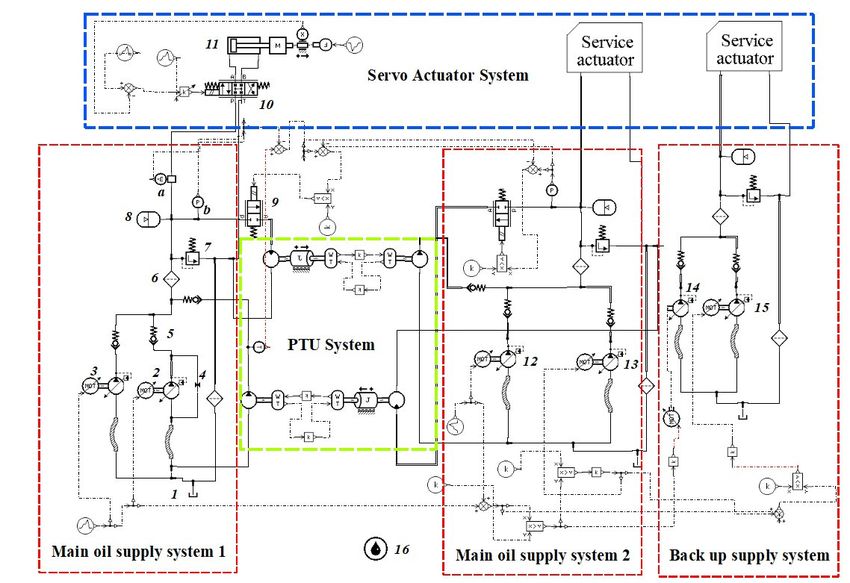
Figure 1. Structure of an aircraft hydraulic system.
Figure 1. Structure of an aircraft hydraulic system.
To highlight
To highlight thethe research
researchfocus,
focus,this
thispaper
paperdescribes
describesthethe
study
studyof the section
of the sectionfrom the
from
oil tank to the actuation system without the driven part or the transmission
the oil tank to the actuation system without the driven part or the transmission part. The part. The nor-
mal operation
normal operation of the system
of the systemmeans
meansthat
thatthe
theinput
inputsignal
signalcan
canbe
betransformed
transformed into
into aa stable
stable
operation of
operation of the
the control
control surfaces.
surfaces. In
In general,
general, an an aircraft
aircraft hydraulic
hydraulic system
system can
can bebe divided
divided
into two
into two parts,
parts, namely,
namely, the
the servo-actuation
servo-actuation systems
systems andand the
the oil
oil supply
supply systems.
systems. They
They are
are
the core components of an aircraft hydraulic system. The aircraft hydraulic
the core components of an aircraft hydraulic system. The aircraft hydraulic system in system in Fig-
ure 1 can
Figure 1 canbe be
established
establishedby by
AMESIM.
AMESIM. The AMESIM
The AMESIM model
model built in in
built this paper
this paperis shown
is shownin
Figure
in Figure2. 2.
In the AMESIM aircraft hydraulic system, being the same as in Figure 1, the oil supply
system is composed of three relatively independent systems: a main oil supply system 1, a
main oil supply system 2, and a back-up oil supply system.
The main oil supply system 1 is powered by a left engine drive pump (EDP,2), and
an electrical motor pump (EMP,3). The main oil supply system 2 is powered by a right
EDP (13) and an EMP (12). The back-up oil supply system is powered by an EMP (14) in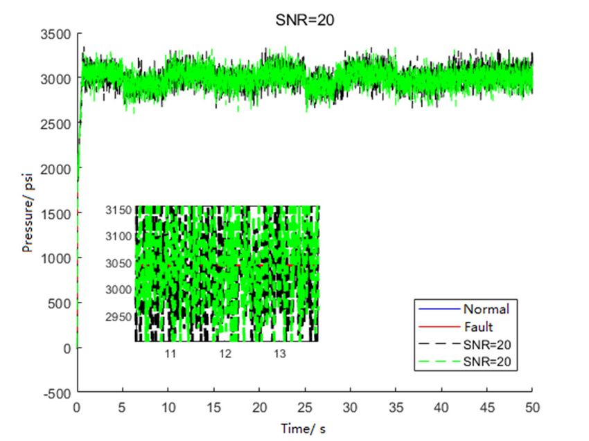
Aerospace 2023, 10, 55 4 of 26
Aerospace 2023, 10, x FOR PEER REVIEW 4 of 27
normal state, and a ram air turbine (RAT,15) in case of the state when the left and right
engines have both failed.
Figure 2. 2.
Figure AnAn
aircraft hydraulic
aircraft system
hydraulic built
system byby
built AMESIM.
AMESIM.
InInthetheAMESIM aircraftsystem
servo-actuator hydraulic
which system,
is in thebeing
bluethe same
dotted as in the
frame, Figure 1, the(11)
actuator oil is
sup-
used
plytosystem
provideismechanical
composed of threefor
energy relatively
different independent
oil users of thesystems: a main
aircraft, suchoilas supply
the landingsystemgear,
1, wing
a main oil aileron,
flap, supply flipper,
system and2, and a back-up
rudder. oil supply
The actuator system.
control value (10) is used to control the
The main
actuator’s oil supply
working timesystem
and oil 1pressure.
is powered by a left engine drive pump (EDP,2), and
an electrical
The green motor pump
dotted (EMP,3).
frame betweenThethemain
main oiloilsupply
supplysystem
system21isand powered
the main byoil
a right
supply
EDP (13) 2and
system is aan EMP (12).
two-way The transfer
power back-upunitoil supply system is
(PTU) system. Inpowered
normal time,by an theEMPPTU(14) in
system
normal
will notstate,
work. andWhen
a ramthe airpressure
turbine (RAT,15)
of one oilin case of
supply the state
system when the
is reduced to aleft
low and right
level, the
PTU system
engines have both will work.
failed. It transfers oil from the high-pressure side to the low-pressure side,
andInmakes the low-pressure
the servo-actuator systemsidewhich
returnistoin a normal
the bluestate.
dotted frame, the actuator (11) is
used to provide mechanical energy for different oil users of the aircraft, such as the land-
ing2.2. Normal
gear, wingStateflap,and Fault flipper,
aileron, State and rudder. The actuator control value (10) is used to
controlIn thethe AMESIM
actuator’s aircrafttime
working hydraulic
and oilsystem,
pressure. one normal state and five kinds of fault
states are considered in this paper.
The green dotted frame between the main oil supply system 1 and the main oil sup-
When2 the
ply system is ahydraulic
two-way system is in operation
power transfer unit (PTU) in a system.
normal state, the EDP
In normal time,(2)theworks
PTUat
a constant
system will notspeed
work.of 5000
When rpm,theand outputs
pressure of pressure of 3000system
one oil supply psi to is
thereduced
aircraft to hydraulic
a low
system.
level, the PTUThe EDPsystem (2)will
delivers
work.oilItflow from oil
transfers thefrom
oil tank
the (1) to the hydraulic
high-pressure side to system,
the low- first
through a one-way value (5), which is to prevent
pressure side, and makes the low-pressure side return to a normal state. the return of hydraulic oil, and then
through an oil filter (6), which is to reduce the temperature of the hydraulic oil and prevent
oilNormal
2.2. pollution.
StateFinally, oil is
and Fault delivered one way to a relief valve (7), which is used to prevent
State
the system pressure from being too high; when the system pressure is over 3400 psi, the
In the AMESIM aircraft hydraulic system, one normal state and five kinds of fault
relief value will open and reduce the system pressure. The other way is to the actuation
states are considered in this paper.
When the hydraulic system is in operation in a normal state, the EDP (2) works at a
constant speed of 5000 rpm, and outputs pressure of 3000 psi to the aircraft hydraulic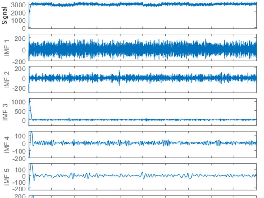
Aerospace 2023, 10, 55                                                                                                                      5 of 26

                                        system. A bladder accumulator (8) ensures system pressure stability when there are sudden
                                        changes in the flow demands.
                                             The five fault states are pump inner leakage (2), filter block (6), relief value spring
                                        failure (7), actuator inner leakage (11), and oil pollution (16). In order to improve the
                                        accuracy of fault diagnosis in the hydraulic system, eight different sensors are used in this
                                        paper. Each state has 8 kinds of different signals, including the pressure in three different
                                        places (pump, filter, and actuator), the flowrate in three different places (pump, filter, and
                                        actuator), the displacement of the actuator, and the velocity of the actuator.

                                        2.3. Data Collection
                                             The data of six states are simulated in the AMESIM hydraulic system. Taking the
                                        aircraft hydraulic system as the research object, eight channels signals of six different states
                                        are collected in this section. The main parameters of the AMESIM simulation model are
                                        given in Table 1. These parameters are used when the hydraulic system is in a normal state.

                                        Table 1. Simulation parameters of the aircraft hydraulic system.

  Number         AME-Element                        Key Parameter                    Value                            Meaning
                                                                                                       The shaft speed is 5000 r/min, and the
      1              signal03                            Output                   5000 r·min−1
                                                                                                         pressure of the pump is 3000 psi.
                                                     Gas pressure                   1885 psi            Accumulator reduces pressure, as an
      3           Accumulato2
                                                 accumulator volume                  2.62 L                    emergency source.
                                                                                                                Pressure relief value,
      4           presscontol01            Relief valve cracking pressure           3436 psi
                                                                                                                for system discharge.
      5                  tank01                     Tank pressure                    50 psi             Booster tank, for pre-boost to 50 psi.
      7              pump13                      Nominal shaft speed              5000   r·min−1            Left engine drive pump (EDP).
                                                                                                        Right EDP, Yellow system EMP, Blue
                                                                                  5000 r·min−1
   11~14             pump13                       nominal shaft speed                                  system EMP, and RAT. Rated pressure
                                                                                  4166 r·min−1
                                                                                                                of RAT is 2500 psi.
                                                                                                            PTU opens when the pressure
     10             constant_3                      constant value                 34.4738 bar          difference between green and yellow
                                                                                                                systems is 34.4738 bar.

                                              The fault states are built according to the normal state with consideration of the five
                                        relative values, including pump leakage (PL), filter blockage (FB), relief valve spring failure
                                        (RF), actuator inner leakage (AIL), and oil pollution (OP). By changing the five different
                                        values, the five fault states can be simulated in the AMESIM hydraulic system. The fault
                                        state parameters are listed in Table 2.

                                        Table 2. Fault state values of the hydraulic system.

  Num          Fault Category and Category Number                            Key Parameter                    Normal Value       Fault Value
     2                        pump leakage-1                         Equivalent orifice diameter (mm)            0.1~0.3              1~2
     6                        filter blockage-2                      Equivalent orifice diameter (mm)              5~7                3~4
     7                   relief valve spring failure-3                     Open pressure (psi)                    3400            2600–3300
    11                    Actuator inner leakage-4                Leakage coefficient   (L·min−1 ·bar−1 )        0~0.01            0.03~0.05
    16                         oil pollution-5                               Air content (%)                     0.1~0.3             5~15

                                              The simulation model is built when the system is stable. This simulation uses the main
                                        oil supply system 1 and the servo-actuator system to simulate the aircraft hydraulic system.
                                        When the system is working normally, it will be considered as the normal state.
                                              The total simulation time is 50 s, including 0–5 s during which the actuator is closed,
                                        5–10 s during which the actuator is opened and moves left, 10–15 s during which the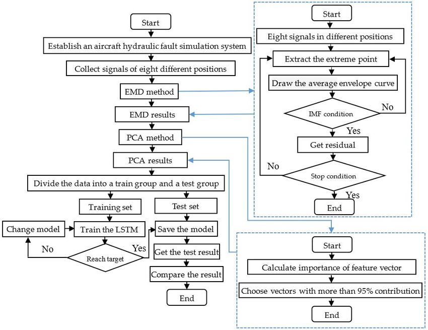
16 oil pollution-5 Air content (%) 0.1~0.3 5~15
The simulation model is built when the system is stable. This simulation uses the
main oil supply system 1 and the servo-actuator system to simulate the aircraft hydraulic
Aerospace 2023, 10, 55 system. When the system is working normally, it will be considered as the normal state. 6 of 26
The total simulation time is 50 s, including 0–5 s during which the actuator is closed,
5–10 s during which the actuator is opened and moves left, 10–15 s during which the ac-
tuator
actuatoris closed, 15–20
is closed, s during
15–20 which
s during the actuator
which is opened
the actuator and moves
is opened right, and
and moves 20–25
right, and
s20–25
during s during which the actuator is closed, and then it returns to this cycle again sim-
which the actuator is closed, and then it returns to this cycle again after this after
ulation has ended.
this simulation hasThe sample
ended. Theratesample
is 100 hz;
rateiniseach
100 simulation,
hz; in eachasimulation,
sample of 5000 number
a sample of
of time
5000 point will
number be collected.
of time point willThe simulationThe
be collected. results are shown
simulation in Figure
results 3. This
are shown simula-3.
in Figure
tion
Thisresult is a comparison
simulation between the
result is a comparison normalthe
between state and the
normal stateair pollution
and state in eight
the air pollution state
different channel signals.
in eight different channelHere, theHere,
signals. oil pollution value is 0.1%
the oil pollution valueinisthe normal
0.1% in thestate and state
normal 15%
in the15%
and faultin state. Duestate.
the fault to the length
Due to theoflength
the article,
of thethe otherthe
article, fault
otherstate simulation
fault results
state simulation
will not be presented.
results will not be presented.
(a) Pressure at pump outlet (b) Fowrate at pump outlet
Aerospace 2023, 10, x FOR PEER REVIEW 7 of 27
(c) Pressure at oil filter outlet (d) Fowrate at oil filter outlet
(e) Pressure at actuator inlet (f) Fowrate at actuator inlet
Figure 3. Cont.
(g) Pressure at actuator inlet (h) Fowrate at actuator inlet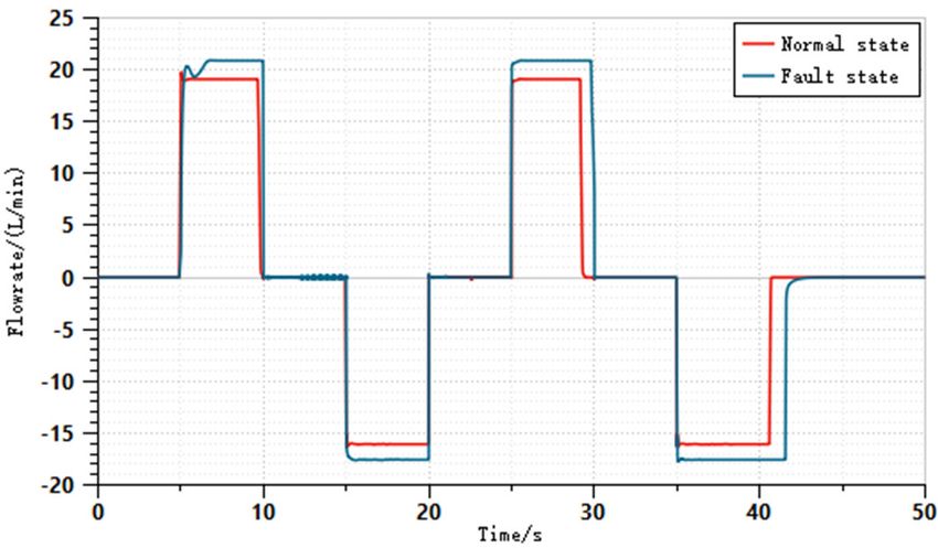
Aerospace 2023, 10, 55 7 of 26
(e) Pressure at actuator inlet (f) Fowrate at actuator inlet
(g) Pressure at actuator inlet (h) Fowrate at actuator inlet
Figure 3.
Figure 3. Comparison
Comparison between
between the
the normal
normal state
state and
and the
the air
air pollution
pollution state.
state.
After the simulations,
simulations,sixsixdifferent
differentkinds
kindsofofdata can
data bebe
can collected. There
collected. are eight
There sig-
are eight
nals that
signals can
that bebe
can collected inineach
collected eachstate,
state,asasshown
shownininFigure
Figure3.
3. These
These include
include the pressure
pressure
the hydraulic
signal at the hydraulic pump
pump outlet
outlet (P
(Ppp); the flowrate signal at the hydraulic pump outlet
(Qpp); the pressure signal (Pff) and the flowrate signal (Qff) at the oil filter exit position;
(Q position; the
the
pressure
pressure signal (P ) and the flowrate signal (Q ) of the actuator inlet; and the velocity
(Pa ) and the flowrate signal (Qa ) of the actuator inlet; and the velocity
a a sig-
nal(Va) and
signal(V the the
a ) and displacement
displacementsignal (Da) (D
signal of athe
) ofactuator. All the
the actuator. Allsignals are shown
the signals in Table
are shown in
3.
Table 3.
Table3.3. Collection
Table Collectionsignals
signalsof
ofsix
sixstates.
states.
Position
Position SignalSignal Mark
Mark Position
Position Signal
Signal Mark
Mark
Pressure
Pressure Pp Pp Pressure
Pressure Pa Pa
Pump
Pump Flowrate
Flowrate Qp Q p Flowrate
Flowrate Qa Q a
Actuator
Actuator
Pressure Pf Displacement Da
Oil filter Pressure Pf Displacement Da
Oil filter Flowrate Qf Velocity Va
Flowrate Qf Velocity Va
3.
3. The
The EMD-LSTM
EMD-LSTM Method Method
3.1. EMD and PCA Method
3.1. EMD and PCA Method
After the six states’ signals have been collected, EMD decomposition needs to be
After the six states’ signals have been collected, EMD decomposition needs to be per-
performed on each signal. The process of EMD is to decompose the original input signal
formed on each signal. The process of EMD is to decompose the original input signal into
into multiple IMFs. These IMFs contain different feathers in each frequency in the input
multiple IMFs. These IMFs contain different feathers in each frequency in the input signal.
signal. During the decomposition of EMD, there is no limitation on the signals of these
During the decomposition of EMD, there is no limitation on the signals of these inputs,
inputs, and it does not require these input signals to be linear or smooth signals. Therefore,
and it does not require these input signals to be linear or smooth signals. Therefore, when
when dealing with the fault signals of a real-world hydraulic system with different noises,
dealing
this withwill
method the fault
have signals
a good of a real-world
effect. hydraulic
At present, system
there are many with different
research noises,
studies this
which
method will have a good effect. At present, there are many research studies which
applied EMD to fault diagnosis [29–32]. However, there is a lack of research on the overall applied
EMD to faultcomprehensive
multi-faults diagnosis [29–32]. However,
diagnosis of anthere is ahydraulic
aircraft lack of research
system.on the overall multi-
faultsThe
comprehensive diagnosis of an aircraft hydraulic system.
general process of the EMD method is as follows: If x(t) is the original signal to
be processed by the EMD, first, we seek all the local maximum values and local minimum
values of the signal x(t). Then, we use the three-time strip curve interpolation methods
and connect all the local maximum points and all the local minimum points to obtain the
maximum envelope curve emax (t) and the minimum envelope curve emin (t); all data points
in signal x(t) are wrapped between these two curves. We calculate the average value of the
emax (t) and emin (t), and mark it as e(t). Then, we subtract the e(t) from the original signal
x(t), and obtain a new signal x1 (t) =x(t)–e(t). At this time, we test whether x1 (t) meets the
two conditions of the IMFs: 1. in the decomposed signal, the equivalent points are equal
to zero or equal to one, and 2. the signal is about the local symmetry of timeline. If it is
satisfied, it is recorded as IMF1 (t) = x1 (t). If it is not satisfied, we use x1 (t) as the original
signal and repeat the above operation.
After that, IMF1 (t) is separated from x(t), and we obtain a residual signal r1 (t), r1 (t)
= x(t) -IMF1 (t). Then, we use r1 (t) as a new original signal to repeat the above operation.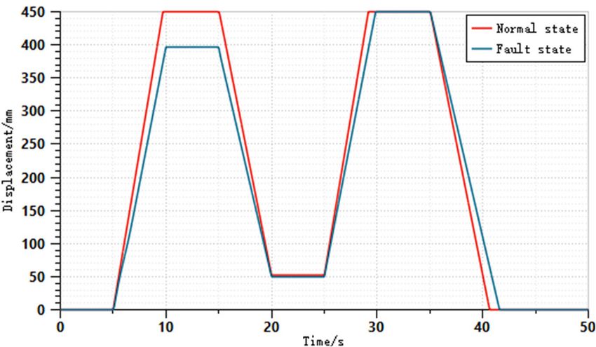
x(t), and obtain a new signal x1(t) =x(t)–e(t). At this time, we test whether x1(t) meets the
two conditions of the IMFs: 1. in the decomposed signal, the equivalent points are equal
to zero or equal to one, and 2. the signal is about the local symmetry of timeline. If it is
satisfied, it is recorded as IMF1 (t) = x1(t). If it is not satisfied, we use x1(t) as the original
Aerospace 2023, 10, 55 signal and repeat the above operation. 8 of 26
After that, IMF1(t) is separated from x(t), and we obtain a residual signal r1(t), r1(t) =
x(t) -IMF1(t). Then, we use r1(t) as a new original signal to repeat the above operation. After
N times, the signal can obtain N components of the IMFs, which can be expressed as fol-
After N times, the signal can obtain N components of the IMFs, which can be expressed
lows:
as follows:
= x ((t)) −
⎧ r1 ((t)) =
− I MF1((t))
⎪ 2 ( ) = 1 ( ) −
r ( t ) = r ( t ) − I MF2(t)
(t)
.…..
(1)
(1)
⎨ .…..
.…..
⎪
⎩rn ((t)) == rn−1 (t) − I MFn(t) (t)
The
Thesignals
signalsafter
afterEMDEMDdecomposition
decompositionare areshown
shownin inFigure
Figure 4. 4. The
The aircraft
aircraft hydraulic
hydraulic
oil
oilfilter
filterblockage
blockagestate stateisisselected
selectedto tothe
theEMD.
EMD.We Wechoose
choosethreethreechannel
channelsignals,
signals,and
andthey
they
are
areQQa,a ,PP
p,pD
,Da. a
The horizontal
. The horizontal coordinates
coordinates areare
thethe
number
number of sampling
of sampling timetime
points, and and
points, the
frequency
the frequency is 100 Hz.Hz.
is 100 TheThe
unitunit
of each point
of each is is
point 0.01 s. s.The
0.01 Thefirst
firstsubfigure
subfigureisisthe
theoriginal
original
signal,
signal, the last
last subfigure
subfigureisisthe theresidual
residual r component,
r component, andand the the
other other subfigures
subfigures areIMFs,
are the the
as shown
IMFs, in Figure
as shown 4.
in Figure 4.
Aerospace 2023, 10, x FOR PEER REVIEW 9 of 27
(a) EMD of Qa
(b) EMD of Pp
Figure 4. Cont.
Aerospace 2023, 10, 55 9 of 26
(b) EMD of Pp
(c) EMD of Da
Figure
Figure 4.
4. EMD
EMDresults
resultsof
ofdifferent
different channel
channel signals.
signals.
The
The oil
oil filter
filter blockage
blockage (FB) (FB) state
state isis simulated.
simulated. The The EMD
EMD of of Q
Qaa obtains
obtains 18 18 IMFs,
IMFs, the the
EMD
EMD of Pp obtains 19 IMFs, and the EMD of Da obtains 12 IMFs. From Figure 4,different
of P p obtains 19 IMFs, and the EMD of D a obtains 12 IMFs. From Figure 4, different
IMFs
IMFs can
can reflect
reflect the
the characteristics
characteristics of of the
the original
original signal
signal to to aa certain
certain extent.
extent. Each
Each original
original
signal obtainaaset
signal can obtain setofof feature
feature vectors
vectors afterafter the EMD,
the EMD, and the andEMDthe results
EMD results can be
can be marked
marked as Fn1=, IMF
as Fn = [IMF [IMF2 ,1,. IMF 2, ...
. . IMF K IMF
, r], ,
with
K r], with
k k
meaning meaning
the the
total total
number number
of IMFsof IMFs
after after
the the
EMD,
EMD, and r meaning
and r meaning the residual
the residual after theafter EMD. the EMD.
From theFrom
three the
setsthree
of EMDsetssignals
of EMD signals
in the in
figures,
the figures, the types of information containing and expressing
the types of information containing and expressing are different, so the total number of are different, so the total
number
IMFs areofnot IMFs are not consistent.
consistent. The IMFs after The IMFsthe EMD afterenriches
the EMDthe enriches the inputoffeatures
input features the LSTM of
the LSTM networks.
networks. However, However,
it is inevitable it is that
inevitable
there are that there are redundancy
redundancy or repetitionorofrepetition
information, of
and the inputand
information, dimensions
the inputofdimensions
the LSTM are notLSTM
of the the same. Therefore,
are not the same.theTherefore,
PCA method theneeds
PCA
to be applied
method needsto toreduce
be applied the dimension
to reduce the of the input IMFs.
dimension of the input IMFs.
Principal component
Principal component analysis analysis (PCA)(PCA) isisaastatistical
statisticalmethod
methodfor forthe
themain
main component
component of
a signal, and converts a set of variables that may exist into a set
of a signal, and converts a set of variables that may exist into a set of linear irrelevant of linear irrelevant variables
through orthogonal
variables transformation.
through orthogonal This set of This
transformation. variables
set ofisvariables
called theismain
calledingredient.
the main The in-
Aerospace 2023, 10, x FOR PEER REVIEW PCA method 10 of 27
gredient. The wasPCAproposed
method was by Karl Pearson
proposed by[33].
Karl Presently,
Pearson [33]. it has been widely
Presently, it has used
been in
many fields,
widely used in such
many as fields,
mode recognition,
such as modesignal processing,
recognition, signal signal compression,
processing, and fault
signal compres-
diagnosis
sion, [34–36].
and fault The PCA
diagnosis method
[34–36]. Thecan PCA ensure
method that theensure
can main characteristics of a signal are
that the main characteristics
nota lacking
of signal are and realize
not lacking theandsimplification
realize the of data; this can
simplification of greatly
data; reduce
this canthethe amount
greatly reduce of
the amount of data that requires subsequent processing. Therefore, training and cal-
data that requires subsequent processing. Therefore, the training and calculation time of
culation time of the LSTM networks can be reduced, and the testing speed becomes faster.
the LSTM networks can be reduced, and the testing speed becomes faster. This process is
This process
shown is shown
in Figure 5. in Figure 5.
Figure 5. PCA method to reduce the information.
Figure 5. PCA method to reduce the information.
Considering that the number of feature vectors are different, we ensure that the error
between the real data after the dimension and the data before the dimension is less than
0.05, that is to keep the information more than 95% of the original features. The number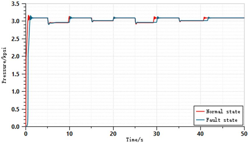
Aerospace 2023, 10, 55 10 of 26
Considering that the number of feature vectors are different, we ensure that the error
between the real data after the dimension and the data before the dimension is less than
0.05, that is to keep the information more than 95% of the original features. The number of
all Fn in this simulation is chosen as 5 IMFs. If the IMFs are higher than 5 for PCA reduction,
the process is shown in Figure 5.
After the EMD and PCA, the extraction feature vector can be expressed as Fn* = [F1, F2,
F3, F4, F5]. After normalization, the feature vectors are as the inputs of the LSTM networks.
The total number of the inputs in the LSTM networks are 40 sets of special feather vectors.
Therefore, each test or train state data set has 40 characteristic vectors.
3.2. Three Inner Structure of LSTM Networks
Long short-term memory (LSTM) neural network is a deformation of recurrent neural
network (RNN). The internal structure of a RNN is a circular structure, and it can retain
a certain degree of time information. Theoretically, the neurons located at the time point
of ti pass their internal information to the neuron ti+1 of the next time point. In this way,
the input information and the output information at the neuron of time point ti can map
the effect of all the previous time points, and form a feedback structure similar to a ring.
However, in an actual application of a RNN, when the distance between ti+m and ti is too
large, there may be a problem that ti cannot map the input and output characteristics of
the time point ti+m . This situation is called the gradient disappearance in the RNN, or
long-term dependence. This problem is solved by the LSTM network algorithm proposed
by Hochreiter [37]. The LSTM network adopts its unique internal three gate units structure,
and through the structure of the three gate units, it can control the transmission rate in the
historical information dissemination in the RNN. The information is sent into the three
different gate units according to the important degree, so it solves the gradient explosion
of the long distance. The mathematical expression of the LSTM model can be written
as follows:
f t = σ W f ·[ x t , h t − 1 ] + b f
it = σ (Wi ·[ xt , ht−1 ] + bi )
ot = σ (Wo ·[ xt , ht−1 ] + bo ) (2)
cet = tan h(Wc ·[ xt , ht−1 ] + bc )
ct = f t ∗ ct−1 + it ∗ cet
ht = ot ∗ tan h(ct )
In Formula (2), t is the time point, xt is the input of the LSTM network, and ht is the
output of the hidden layer in the network. ct is called the unit state, and it is a unique
structure in the LSTM network. ct is used to preserve information, forget information, or
control the flow of information by passing the information to subsequent neuron cells. The
first three formulas are the gate unit structure, namely forgotten gate f t , input gate it , and
output gate ot . These three gate structures assist ct to delete or add information, and limit
the output range between 0 and 1 by the Sigmoid layer. When the output is 0, it means
that the information is abandoned. When the output is 1, it means that the information
is all recorded. σ is the active function, W is the weighted value of the network, and b is
the offset of the network. These two parameters will be optimized during the network
training. The symbols “.” and “*” here represent the matrix multiplication and the point
multiplication between the same dimension matrix. The structure of the LSTM is shown in
Figure 6a.
In order to choose the best internal structure of the LSTM, the other two different
internal structures of LSTM networks are considered in this paper. LSTM also has a
variety of internal structural design methods, and by changing the internal structure of the
network, it can change its effect on fault classification. Among the current commonly used
methods, there is a structure called LSTM with observation holes. This network structure
is set up inside the network by changing the settings of the three units, and adds a part
of the ct-1 observation for each unit status at the previous time point. The structure of
LSTM with observation is shown in Figure 6b. Compared to the traditional LSTM networkAerospace 2023, 10, 55 11 of 26
structure, this structure is more complicated, and the mathematical expression can be
written as follows:
f t = σ W f ·[ x t , h t − 1 , c t − 1 ] + b f
·[
i t = σ ( Wi x t , h t − 1 , c t − 1 ] + b i )
ot = σ (Wo ·[ xt , ht−1 , ct ] + bo ) (3)
cet = tan h(Wc ·[ xt , ht−1 ] + bc )
Aerospace 2023, 10, x FOR PEER REVIEW c = f t ∗ ct−1 + it ∗ cet 12 of 27
t
ht = ot ∗ tan h(ct )
(a) Stucture of the LSTM (b) Structure of the LSTM with observation
(c) Stucture of the GRU
Figure
Figure 6.
6. Three
Three different
different inner
inner structures
structures of
of LSTM networks.
LSTM networks.
3.3. The LSTM Network
In addition, there Structure
is anotherDesign
structure of LSTM which is called gated recurrent unit
(GRU),The input layer of the LSTMof
that is applied in the field is fault diagnosis
40 IMFs. In theand has alayer,
LSTM relatively
each novel
internalstructure.
unit is
Compared to the traditional LSTM, it simplifies the internal structure, but
spliced in order, and at each time, on the long step, we perform a state of states at a hiddenthe accuracy of
classification
layer and dataofupdate;
a GRU canthis achieve
process considerable or time
is called a unit betterstep
results. In addition, it is easier to
process.
trainThe
in comparison,
characteristic and it can
input at largely improve
the current training
moment and efficiency.
the implicitTherefore,
unit statusGRU is more
of the pre-
inclined
vious to be used
moment in the
are used asfield of fault
the input diagnosis.
of the hidden It simplifies
unit the step
in the next internal structure
to update the of the
state.
standard LSTM, integrates the forgotten gate and the input gate as
The mathematical expressions of the three different LSTM methods are shown in Formu- a new structure called
update
las (2)–(4). zt , and
gateAfter introduces
that, the output rt of
as the
the reset
LSTMgate.
layerThe structure of
is connected the aGRU
with fullyisconnected
shown in
Figure 6c. Its expression can be written as follows:
layer (FC 1), and this fully connected layer uses the ReLU activation function to restrict
the output above 0. Then, the
output of the FC 1 is connected to a second fully connected
zt = σ (Wz ·[ xt , ht−1 ] + bz )
layers (FC 2). This layer with
rthe=SoftMax
function layer forms the output layer. The out-
σ (W ·[ xt , ht−1 ] + br )
put is a possible state for theetsamples,r and it represents five types of fault states and(4)
a
ht = tanh(Wh ·[ xt , rt ∗ ht−1 ] + bh )
normal state. The structureis shown in the Figure 7. e
h t = z t ∗ h t −1 + (1 − z t ) ∗ h t
Figure 6 shows the structures of the three different kinds of LSTM neural networks.Aerospace 2023, 10, 55 12 of 26
3.3. The LSTM Network Structure Design
The input layer of the LSTM is 40 IMFs. In the LSTM layer, each internal unit is spliced
in order, and at each time, on the long step, we perform a state of states at a hidden layer
and data update; this process is called a unit time step process.
The characteristic input at the current moment and the implicit unit status of the
previous moment are used as the input of the hidden unit in the next step to update
the state. The mathematical expressions of the three different LSTM methods are shown
in Formulas (2)–(4). After that, the output of the LSTM layer is connected with a fully
connected layer (FC 1), and this fully connected layer uses the ReLU activation function
to restrict the output above 0. Then, the output of the FC 1 is connected to a second fully
connected layers (FC 2). This layer with the SoftMax function layer forms the output layer.
Aerospace 2023, 10, x FOR PEER REVIEW
The output is a possible state for the samples, and it represents five types of fault13states
of 27 and
a normal state. The structure is shown in the Figure 7.
Figure 7.
Figure 7. The
Thestructure
structureofofLSTM
LSTMnetworks
networksforfor
hydraulic system
hydraulic fault
system diagnose.
fault diagnose.
The
The input
input layer
layer is
is 40
40 characteristic
characteristic data
data samples
samples after
after preprocessing.
preprocessing.The Theinput
inputneu-
neurons
are 40, each data column length is 5000, the sampling frequency is 100 Hz, and and
rons are 40, each data column length is 5000, the sampling frequency is 100 Hz, the
the number
number of neurons in the LSTM layer is 12. The number of neurons on
of neurons in the LSTM layer is 12. The number of neurons on the first fully connected the first fully con-
nectedislayer
layer is 12.
12. The The number
number of neurons
of neurons on the second
on the second fully connected
fully connected layer islayer
6. The is number
6. The of
number of neurons in the Softmax layer is also 6, which is the six different
neurons in the Softmax layer is also 6, which is the six different states’ output. states’ output.
The
The three
three LSTM
LSTMmodels
modelsininthis
thisarticle areare
article built
builtbased
basedon on
the the
TensorFlow2.0
TensorFlow2.0 GPUGPU
framework, computer matching: Intel (R) Core (TM) i5-12400F CPU @
framework, computer matching: Intel (R) Core (TM) i5-12400F CPU @ 4. 40 GHz + NVIDIA 4. 40 GHz + NVIDIA
GEFORCE RTX
GEFORCE RTX 2070
2070 super
super88 GB.
GB.The
Thebatch
batchsize
sizeisisset
settoto800,
800,and
andthe
themaximum
maximumnumber number of
of iterations is 200 times. During the model training, the loss of the task is calculated with
iterations is 200 times. During the model training, the loss of the task is calculated with
cross-entropy loss, and it is used as the total loss of the model. Due to the fast convergence
cross-entropy loss, and it is used as the total loss of the model. Due to the fast convergence
speed of the Adam optimizer and less memory demand, it can reduce the performance of
speed of the Adam optimizer and less memory demand, it can reduce the performance of
the device. Therefore, the Adam algorithm is chosen as the optimizer and the learning rate
the device. Therefore, the Adam algorithm is chosen as the optimizer and the learning rate
is set to 0.001 to optimize the model. The proportion of the task is adjusted to the optimal
is set to 0.001 to optimize the model. The proportion of the task is adjusted to the optimal
training effect of the tasks. The main parameters of the network are shown in Table 4.
training effect of the tasks. The main parameters of the network are shown in Table 4.
Table 4. Optimal parameter values for the LSTM.
Table 4. Optimal parameter values for the LSTM.
Parameter Name Value
Parameter Name Value
Lr 0.001
Lr
Lr decaying 0.001
lr = lr × 0.9/epoch
Lr decaying lr = lr × 0.9/epoch
Batch size 800
Batch size 800
Dropout raterate
Dropout 0.4 0.4
Training epochs
Training epochs 200 200
Activation function
Activation function ReLU ReLU
Optimizer
Optimizer AdamAdam
Table 4 lists the optimal values for the network parameters, where lr is the learning
rate and the batch size refers to the number of batch samples. The dropout rate refers to
the random resetting of the neuron output to zero with a certain probability during train-
ing, which can help reduce over-fitting. The optimal parameter is obtained based on theAerospace 2023, 10, 55 13 of 26
Table 4 lists the optimal values for the network parameters, where lr is the learning
rate and the batch size refers to the number of batch samples. The dropout rate refers to the
random resetting of the neuron output to zero with a certain probability during training,
which can help reduce over-fitting. The optimal parameter is obtained based on the actual
situation of the aircraft hydraulic system and multiple experiments.
3.4. EMD-LSTM Method for the Aircraft Hydraulic System
This paper focuses on the fault diagnosis of an aircraft hydraulic system in a noisy
environment,
Aerospace 2023, 10, x FOR PEER REVIEW and a fault diagnosticmethod based on EMD-LSTM is proposed in 14 this
of article.
27
The collection data include the six different states of signal data obtained by the AMESIM
simulation in Section 2. Eight sensors are used for each state to collect data, including three
data sets of three
including oil pressure
data sets (pump, filter, and
of oil pressure actuator),
(pump, filter, three data setsthree
and actuator), of oildata
flowsets
rateof(pump,
oil
filter,
flow rate (pump, filter, and actuator), a displacement data set, and a velocity data method
and actuator), a displacement data set, and a velocity data set. First, the EMD set.
is First,
usedthe to decompose
EMD methodthe collected
is used eight-channel
to decompose aircraft
the collected hydraulic aircraft
eight-channel systemhydraulic
fault data to
obtain
system thefault
data characteristics
data to obtain the of thecharacteristics
data IMFs. Then,ofthe thePCA method
IMFs. is used
Then, the to reduce
PCA method is the
dimensions
used to reduceof thethe
IMFs. On the of
dimensions premise
the IMFs.of ensuring the effectiveness
On the premise of ensuringof thethe data, the main
effectiveness
of thecomponent
feature data, the main feature component
is extracted is extracted
from the different from the different
decomposition decomposition
results of multiple groups
to results
reduceofthe multiple groups to reduce
data processing amount thefor
data processingfault
subsequent amount for subsequent
diagnosis, fault di- the
and to improve
agnosis, and
efficiency and to improve
the speed of thefault
efficiency and the
diagnosis. speed of
Finally, thefault
IMFsdiagnosis.
with high Finally, the IMFsafter
correlations
with highreduction
dimension correlations areafter
useddimension reduction
as the training andare testused
setsas
tothe training
train andthe
and test testthree
sets LSTM
to
train and test the three LSTM networks with different internal structures.
networks with different internal structures. The flow chart of the EMD-LSTM method is The flow chart
of thein
shown EMD-LSTM
Figure 8. method is shown in Figure 8.
Figure 8. The flow chart of the EMD-LSTM fault diagnostic method for aircraft hydraulic system.
Figure 8. The flow chart of the EMD-LSTM fault diagnostic method for aircraft hydraulic system.
4. The Simulation Results of the EMD-LSTM Method
4.1. Data Collection and Feature Extraction
The data samples used for training and testing of the LSTM are obtained through
simulation of the aircraft hydraulic system model in the second section. The six categories
of states contain a normal state and five types of failure are simulated. Among them, 1000Aerospace 2023, 10, 55 14 of 26
4. The Simulation Results of the EMD-LSTM Method
4.1. Data Collection and Feature Extraction
The data samples used for training and testing of the LSTM are obtained through
simulation of the aircraft hydraulic system model in the second section. The six categories
of states contain a normal state and five types of failure are simulated. Among them,
1000 experimental samples are collected, of which 800 samples are randomly selected as
the training sets and 200 samples are selectd as the testing sets.
In an environment with higher noise, featured information is often drowned in noise.
It is difficult to use the timing signal training network for fault diagnosis. Therefore, signal
preprocessing is considered in this paper, and the feature information is obtained before the
LSTM fault diagnosis. In this paper, the data are preprocessed using the EMD method to
obtain different IMFs. Then, the PCA method is used to reduce the dimension of the IMFs
obtained. There are 5 IMFs in each channel, and we transform the network training data set
from 8 channels to 40 channel sample sets. The length of each data sample is 5000 sampling
points, and the sampling frequency is 100 Hz. These characteristics of different IMFs can
reflect the characteristics of different states of hydraulic systems. The number of samples in
different types is specifically shown in Table 5.
Table 5. Different samples used for the aircraft hydraulic fault diagnosis.
Training Testing Sample
Class Number States Fault Value Feature
Data Data Length
0 Normal state - 800 200 5000 40
1 Pump leakage 1~2 800 200 5000 40
2 Filter blockage 3~4 800 200 5000 40
3 Relief valve spring failure 2600–3300 800 200 5000 40
4 Oil pollution 5~15 800 200 5000 40
5 Actuator inner leakage 0.03~0.05 800 200 5000 40
4.2. The Fault Diagnostic Results in the Comparison of Three EMD-LSTM Methods
In the simulation experiment, the LSTM neural networks with three different internal
structures are used to perform fault diagnosis of the hydraulic system. The accuracy, testing
time, and hardware size are considered in the three LSTM fault diagnostic methods to
compare the fault diagnostic effect. In order to compare the impact of structure on the
LSTM network, the other parameters of the network are set to stay consistent, and only the
internal structure in the LSTM layer is changed. The confusion matrix of the three different
structures of LSTM network diagnosis is shown in Figure 9.
From Figure 9, the accuracy of the three LSTM methods are high, and the accuracy of
all methods reaches more than 97%, Therefore, these three methods are feasible methods
for the fault diagnosis of aircraft hydraulic systems. Relatively, the accuracy of the GRU
method is highest and reaches more than 98%.
From a single failure, the accuracy of class 4 is lower than the other classes. Class 4 is
the oil pollution state of the aircraft hydraulic system. From the figures, the accuracy of the
LSTM method is 86%, the accuracy of the LSTM with observation is 83.5%, the accuracy of
the GRU method is 90%, and almost all of the oil pollution states predict the normal state.
This is because when oil pollution is under a low level, it has a small impact on the entire
aircraft hydraulic system. Therefore, inaccurate situations appear in the fault diagnosis.
In general, low oil pollution degree does not have a great impact on the aircraft hydraulic
system, and can reduce oil pollution by regular replacement of hydraulic oil filters. Specific
overall accuracy, system training time, and hardware resource consumption are shown in
Table 6.In the simulation experiment, the LSTM neural networks with three different internal
structures are used to perform fault diagnosis of the hydraulic system. The accuracy, test-
ing time, and hardware size are considered in the three LSTM fault diagnostic methods to
compare the fault diagnostic effect. In order to compare the impact of structure on the
LSTM network, the other parameters of the network are set to stay consistent, and only
Aerospace 2023, 10, 55 15 of 26
the internal structure in the LSTM layer is changed. The confusion matrix of the three
different structures of LSTM network diagnosis is shown in Figure 9.
Aerospace 2023, 10, x FOR PEER REVIEW 16 of 27
(a) LSTM (b) LSTM with observation
(c) GRU
Figure 9. The confusion matrix of the three different structures of LSTM.
Figure 9. The confusion matrix of the three different structures of LSTM.
TableFrom Figure 9,
6. Simulation the accuracy
results ofLSTM
of the three the three LSTM methods are high, and the accuracy
methods.
of all methods reaches more than 97%, Therefore, these three methods are feasible meth-
ods Class Algorithm
for the fault diagnosis Accuracy/%
of aircraft hydraulic systems. Test Time/s the accuracy
Relatively, Software/Mb
of the
GRU method
1 is highest and reaches more than
LSTM 98%.
97.33 1.68 5.9
2
From LSTMfailure,
a single with observation
the accuracy of class 97.08
4 is lower than1.77
the other classes.7.5
Class 4 is
the oil3 pollution state of GRU
the aircraft hydraulic 98.25
system. From 1.61 3.2
the figures, the accuracy of
the LSTM method is 86%, the accuracy of the LSTM with observation is 83.5%, the accu-
racy ofThethesimulation
GRU method results showand
is 90%, thatalmost
the accuracy ofoil
all of the thepollution
three LSTM methods
states predict is higher
the nor-
than 97%, and the GRU method has the highest accuracy at 98.25%. These
mal state. This is because when oil pollution is under a low level, it has a small impact on simulation
results
the entireshow the hydraulic
aircraft method ofsystem.
EMD-LSTM is theinaccurate
Therefore, best method for fault
situations diagnosis
appear in the of an
fault
aircraft hydraulic system. In the comparison of the testing time and hardware
diagnosis. In general, low oil pollution degree does not have a great impact on the aircraft resource
consumption,
hydraulic it can
system, andbecan
seen that the
reduce testing time
oil pollution is all relatively
by regular short.
replacement of Basically,
hydraulic the
oil
filters. Specific overall accuracy, system training time, and hardware resource consump-
tion are shown in Table 6.
Table 6. Simulation results of the three LSTM methods.Aerospace 2023, 10, 55 16 of 26
operation time can be counted. In terms of hardware resource consumption, the GRU
method has simplified the input door and output door, and due to the simple internal
structures, the GRU is more advantageous than the LSTM and the LSTM with observation
in terms of hardware resource consumption.
Comparing Figure 9 and Table 6, the internal structure of the GRU as the LSTM
network is more suitable for the fault diagnosis of aircraft hydraulic systems, and the
research on anti-noise performance will be based on EMD-GRU.
4.3. EMD-GRU Network Structure and Parameter Optimization
To optimization the performance of the EMD-GRU model, the GRU network structure,
the learning rate, and the batch size are chosen to test the EMD-GRU method.
(1) The structure of the method will affect the fault diagnostic results. In order to
prove the advantages of the EMD-GRU method in this article, three comparison classes of
different structures are selected to compare with the EMD-GRU method.
The first class does not use the EMD method or the PCA method, and directly uses
the 8-channel signals to train and test the GRU networks. The second class does not use the
PCA method and uses all the IMFs to train and test the GRU networks. The third class uses
the EMD method and PCA method, but the GRU networks are separated to eight different
GRU networks, and each network uses five IMFs to train and test the GRU. At last, the
eight GRU networks are used to obtain eight fault diagnostic results, and the eight fault
diagnostic results are used to vote for the final result of this method.
To test the effect of structure on the fault diagnostic results, the parameters in the
different structures are the same. Each structure is simulated 10 times to obtain the average
accuracy and testing time. The simulation results are shown in Table 7.
Table 7. The simulation results of different network structures.
Class Fault Diagnostic Model Structure Accuracy Test Time Mode Size
1 GRU without EMD 93.16% 1.31 s 2.6 mb
2 GRU without PCA 96.33% 3.99 s 7.3 mb
3 EMD-8-GRU 95.71% 1.43 s 10.3 mb
4 EMD-GRU 98.25% 1.61 s 3.2 mb
From the simulation results, it can be seen, in the class of the structure that does not
use EMD for feature extraction, the accuracy decreases significantly. The accuracy of the
GRU network structure reaches 93.16%. From class 2, which is the structure that does
not use PCA dimension reduction, the accuracy rate also decreases, but the decline is not
obvious, with only about 2% decrease. Therefore, the EMD decomposition is effective for
the extraction of features. The IMFs have not been reduced by PCA, so data redundancy
and duplication lead to an increase in testing time, because the input in each group of
test groups tested increases significantly. According to the analysis of 3.1, IMFs increase
from 5 to 15–19. Therefore, PCA dimension reduction can also effectively increase the
accuracy of GRU fault diagnosis. From class 3, the EMD and PCA methods are used in this
class. However, during the training process of the GRU, the features of 40 IMFs are not
processed into the same GRU networks. Instead, eight GRU networks with homogeneous
structures are used for separate training, then the voting decision is used to classify the
states. In this process, there is a problem with the integrity of the information; as a result,
the accuracy rate also decreases, but it is still higher than the accuracy of the solution that
does not adopt EMD. However, the size of the model under this situation is the largest, and
it is not suitable for application in an aircraft hydraulic system because multiple network
operations at the same time take up more hardware equipment resources, and it does not
bring a significant increase in detection speed or a significant improvement in accuracy.
According to the content of the above table, it can be seen that the EMD method
feature extraction is used, and the PCA method is used to reduce the dimension. Finally,
the 40 IMFs is introduced into the same GRU network for training. In this way, the accuracyAerospace 2023,
Aerospace 10, x55FOR PEER REVIEW
2023, 10, 1817ofof27
26
of the 98.25%,
reach EMD-GRU andishardware
the highest. The accuracy
resource of the internal
consumption structure
is relatively of the
small; GRU
this can reach
structure of
98.25%, and hardware resource consumption is relatively
GRU is the best structure for aircraft hydraulic system fault diagnosis. small; this structure of GRU is
the best structure for aircraft hydraulic system fault diagnosis.
(2) The learning rate and the batch size. In addition to the structure of the model, the
(2) The learning rate and the batch size. In addition to the structure of the model, the
GRU internal parameters’ setting will also affect the effectiveness of the fault diagnosis.
GRU internal parameters’ setting will also affect the effectiveness of the fault diagnosis. The
The learning rate and the batch size have a greater impact on the GRU networks. We an-
learning rate and the batch size have a greater impact on the GRU networks. We analyze
alyze the effects of these two parameters and select the best parameters.
the effects of these two parameters and select the best parameters.
To prevent the simulation from being affected by other factors, a single variable is
To prevent the simulation from being affected by other factors, a single variable is
used to simulate, and each training only changes the value of one parameter, while all
used to simulate, and each training only changes the value of one parameter, while all other
other parameter values are fixed. The input signals are 40 characteristic IMFs, and the
parameter values are fixed. The input signals are 40 characteristic IMFs, and the internal
internal structure also uses the GRU structure.
structure also uses the GRU structure.
The learning rate has a great impact on the reverse update speed of the GRU network.
The learning rate has a great impact on the reverse update speed of the GRU network.
If the learning rate is too large, it will cause the network parameters to swing back on both
If the learning rate is too large, it will cause the network parameters to swing back on both
sides
sidesofofthe
the optimal
optimalsolution
solutionandanditit will
will be
be difficult
difficult to
to obtain
obtain the
the optimal
optimal solution.
solution. IfIf the
the
learning rate is too small, it will cause the gradient to drop too much
learning rate is too small, it will cause the gradient to drop too much and cause the and cause thegradient
gradi-
ent to disappear.
to disappear. Therefore,
Therefore, the
the GRUGRUcan canincrease
increaselearning
learningraterate attenuation
attenuation to to prevent
prevent the the
gradient from disappearing.
gradient from disappearing.
The
Thebatch
batchsize
sizeisisa amethod
methodofof updating
updating thethe
network
network parameters
parameters to divide
to dividethe the
input in-
sample in the network training. Avoid the input of a single sample that
put sample in the network training. Avoid the input of a single sample that causes the causes the optimal
problem. IncreasingIncreasing
optimal problem. the number theofnumber
iterations can increase
of iterations canthe accuracy
increase the of the network.
accuracy of the
However, the network
network. However, thetraining
network time and fault
training timedetection
and faulttime will betime
detection extended.
will beThe simu-
extended.
lation results areresults
The simulation shownare in shown
Figure 10 and Table
in Figure 8. Table 8.
10 and
(a) Learning rate (b) Batch size
Figure 10. The effect of different parameters on the accuracy of fault diagnosis.
Figure 10. The effect of different parameters on the accuracy of fault diagnosis.
Table
Table 8.
8. The
The simulation
simulation results
results of
of different
different learning
learning rates
rates and
and batch
batch size.
size.
Learning rate
Learning rate
0.1
0.1
0.01
0.01
0.001
0.001
0.0001
0.0001
0.00001
0.00001
0.000001
0.000001
Accuracy/%
Accuracy/% 25.5
25.5 60.4
60.4 91.2
91.2 98.1
98.1 93.2
93.2 79.2
79.2
Training time/s
Training time/s 2222 4747 8585 116
116 456
456 695
695
Batch size
Batch size 100
100 200
200 400
400 800
800 1200
1200 1600
1600
Accuracy/%
Accuracy/% 63.5
63.5 85.2
85.2 96.8
96.8 98.4
98.4 94.5
94.5 88.2
88.2
Training time/s
Training time/s 283
283 209
209 135
135 105
105 99
99 92
92
Ascan
As canbebeseen
seenfrom
fromFigure
Figure10a,
10a,the
thelearning
learningrate
ratecan
canaffect
affect the
the accuracy
accuracyof ofthe
thefault
fault
diagnostic results of the GRU network. When the learning rate is relatively low, the learning
diagnostic results of the GRU network. When the learning rate is relatively low, the learn-
ing speed of the network is fast, and as a result, the accuracy of the fault diagnosis isYou can also read