AC Coupling with Time of Use (TOU) using the Mojave Inverter
←
→
Page content transcription
If your browser does not render page correctly, please read the page content below
AC Coupling with Time of Use (TOU)
                    using the Mojave™ Inverter
This application note explains how to set up a connection technique called AC coupling. In AC
coupling, a non-storage-based grid-dependent inverter (GDI) can be connected with an energy storage
system (ESS) like the Mojave inverter from OutBack Power™. This note also discusses Time of Use
(ToU) with the Mojave inverter for utilizing onsite renewable energy during expensive peak demand
rate periods.

Introduction
Adding storage to a grid-dependent system with the Mojave inverter provides backup power that would
not otherwise be possible. Connecting an AC-coupled system with a GDI utilizes a frequency-shifting
technique that safeguards overcharging of the battery bank by closely regulating voltage and current
limits. Advanced sense circuits and software rapidly increase and decrease the inverter output
frequency, providing a well-regulated power output from the GDI. The result is a high-performing
AC-coupled system. This is particularly true in the case of a Freq/Watt-compliant GDI that responds to
closed-loop control.
The Mojave inverter’s advanced grid management can also significantly reduce utility bills by regulating
the grid connection so that expensive time-of-use rate periods are avoided. After entering the time
window of the rate period to be avoided, the inverter does the rest. Additionally, some utilities do not
allow grid charging of the storage system batteries. For these applications, the Mojave inverter’s
Charge from grid limit can be set to zero.
The aforementioned cases assume the renewable energy (RE) site has a net metering agreement with
the local utility that exports any unused power back to the utility grid. The AC coupling technique that
has been discussed is only implemented when the grid is down. However, some site owners are
unable to obtain a connection agreement. In other cases, the RE export credit is so low that by need or
preference, the site owners would like to self-consume all available RE.
Since the Mojave inverter’s output and input are connected only through the internal grid relay, it’s not
possible to manage the GDI output when grid-connected — only when the system is off-grid, using
frequency shifting. Therefore, any self-consumption or non-export function when grid-connected will
need to be managed by the GDI itself. In this situation, when the grid is live, the Mojave inverter is
basically a copper wire between the GDI output and the grid.

©2022 OutBack Power | an EnerSys company     FA-MM-02/17/2022                                    Page 1 of 10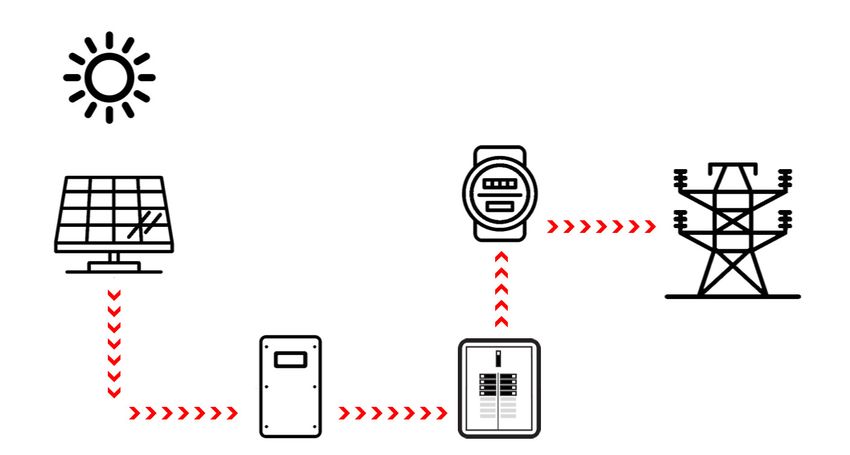
OutBack Power | Application Note

Theory of Operation – Live Grid
Figure 1 shows the current path for a normal GDI from the photovoltaic (PV) panels through the inverter,
to the main service panel. and on out to the grid. In a normal GDI application, power produced from the
PV array is consumed by loads connected to the main service panel with excess power going out to the
grid. However, with grid loss the GDI has no way to synchronize itself to the grid – a requirement for
operation – so it shuts down and is unable to use any RE from the PV array.

                                 Figure 1 – Normal GDI Power Flow

By connecting (coupling) the output of the GDI to the Mojave inverter’s output, Figure 2, the Mojave
inverter can act like a grid source to which the GDI can synchronize. The system can process power
from the PV array to a backup load panel. The backup load panel is required so loads can be powered
from either or both inverters without backfeeding the main panel during a grid outage. (See next section
on Grid Outage operation). Figure 2 shows the new current paths from the PV array which now includes
the backup load panel, the battery bank, as well as main service panel loads. RE will continue out to the
utility grid if any excess PV power has not been consumed onsite.

                            Figure 2 – GDI Power Flow with Active PV

©2022 OutBack Power | an EnerSys company    FA-MM-02/17/2022                                   Page 2 of 10
OutBack Power | Application Note

In addition to exporting GDI current to the main panel, a separate parallel current path to charge the
battery bank from PV power can exist if either the Refloat or Rebulk charging voltages are reached.
However, with a live grid and no PV available, the backup load panel and battery charging (if needed) will
be powered from the grid as shown in Figure 3, unless the Charge from grid limit has been set to zero.

                              Figure 3 – GDI Power Flow without PV

Theory of Operation – With Grid Outage
During a grid outage when the sun is shining, the Mojave becomes an AC source to which the GDI can
synchronize (Figure 4). This allows the PV power to flow to the backup panel’s connected loads, as well
as charge the batteries if the GDI is generating more power than can be absorbed by the loads.
Figure 4 shows all possible current flows, the paths of which can change depending on several different
factors. If the PV generation can satisfy the backup panel and battery charging loads, then PV power
flows in those two directions. If the backup panel load demand exceeds the GDI power generation, then
the Mojave inverter will stop charging the battery (if Absorb or Float charging is active) and invert DC
power from the battery bank and contribute current to the backed-up loads in parallel with the GDI.

    Figure 4 – AC-Coupled Current Flows with Sufficient Load or Charging Demand

©2022 OutBack Power | an EnerSys company    FA-MM-02/17/2022                                   Page 3 of 10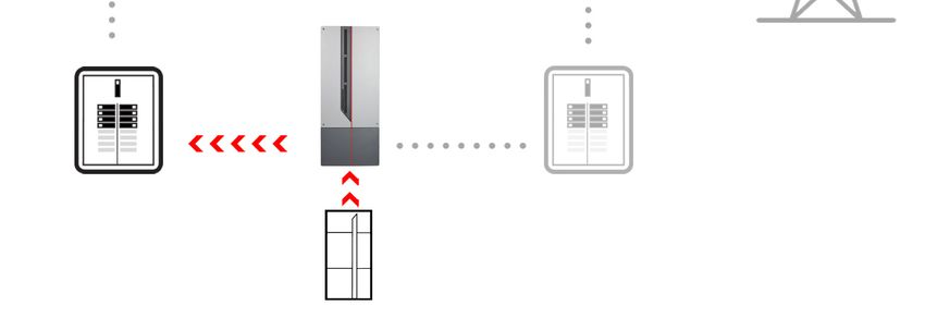
OutBack Power | Application Note

If the batteries become fully charged and the load demand falls below the GDI power production, then
the excess power from that production will flow back through the Mojave inverter in an unregulated
charge to the batteries. When the battery voltage raises more than 0.4 volts above the active charging
voltage target, then the Mojave inverter begins to shift its output frequency above 60 Hz until the battery
voltage starts to level or drop off, but not above 64.5 Hz. The inverter’s frequency shift regulation will
also be enabled if the DC charge current coming back onto the battery bank exceeds the Max charge
current setting.
       EXAMPLE: There is a grid outage and the Mojave inverter becomes the new AC source for the
       GDI which then delivers 3400 watts to the load. The load then drops to 1,000 watts, meaning the
       other 2400 watts (50 Adc at 48 Vdc) will come back through the Mojave inverter to the battery
       bank. If the 50 Adc GDI charging current is less than the maximum charging limit, then it will
       continue delivering charge current to the battery bank. If greater than the maximum charging
       limit, the Mojave inverter output frequency will start to rise until the GDI reduces its output if
       Freq/Watt compliant. If non-Freq/Watt compliant, the GDI will just go offline. If the backfeed
       current to the battery bank stays below the charge limit, but the battery voltage eventually rises
       above the active voltage target (Absorb, Float or Sell), then frequency shift will also be enabled.
There is a significant installed base of non-Freq/Watt legacy GDI products that will just simply go offline
and wait to reconnect for the time specified by the local jurisdiction (usually 5 minutes in North America).
Newer Freq/Watt compliant inverters may actually “feather” back their output to allow some degree of
charging regulation to the battery bank. Depending on the difference between load demand current and
GDI output current, this feathering back of the GDI output will usually prevent shut down of the Freq/Watt
compliant GDI.
Should the GDI go offline, then the Mojave inverter will power the loads as indicated in the backup mode
of operation. See Figure 5. After the reconnect time period, the GDI will try to reconnect to the Mojave
inverter’s output voltage where the cycle would repeat again until the load or battery charging demand
increases, or PV production goes down, or some combination thereof.

                        Figure 5 – Off-Grid Current Flow due to PV Loss
                           or GDI Power Overcharging Battery Bank

©2022 OutBack Power | an EnerSys company       FA-MM-02/17/2022                                         Page 4 of 10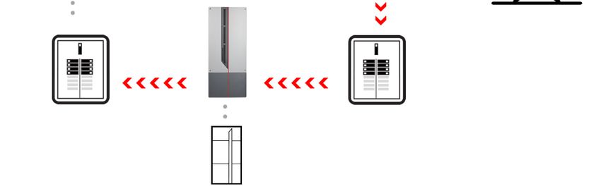
OutBack Power | Application Note

Once PV production is gone for the day, the Mojave inverter will power the loads in the backup mode
until sun returns the next day, or the battery bank reaches the inverter’s low battery cutout (LBCO)
voltage. If the battery bank reaches LBCO, then the inverter can no longer back up the loads. It also
can no longer be a voltage source for the GDI to start again and recharge the batteries. However, the
Mojave inverter will continue to discharge the batteries during LBCO as the inverter standby mode still
uses power even when disconnected from the loads.
To recover the batteries, a DC charging source must be connected to the battery bank in order for the
system to recover and begin normal operation again.

                               NOTE:
                               The Mojave inverter can AC couple up to 7.6 kVA of the GDI output power.

Solution
Hardware Connections
Setting up the GDI for AC-coupled operation with the Mojave inverter requires a connection between
the AC outputs of both inverters. This connection is normally made in the backup load panel which is
shown in Figure 6.

                6kW PV Array

                                            7.6 kW Grid Dependent Inverter
                       String                                                                              120V/240V
                      Combiner                                                                             GRID FEED

                                                                                           120V/240V
                                                                                           Main Service
                                                                                                               M
                                                                                                Panel
                                                                                             Disconnect
                120V/240V Backup
                   Load Panel

                     Panel                                         Mojave Inverter
                  Disconnect

                                                                                                          60A 120V/240V

                                                                   Mojave BOS

                                                             AC Out BUS Grid   AC In Bus
                                                               60A DPST        60A DPST

                                                                    AC In BUS Gen
                                                                      60A DPST

                                        G
                                                                   DC Neg      DC Pos
                                    Generator

                                                                          48V

     Figure 6 – Single line diagram of GDI inverter connection to Mojave inverter

©2022 OutBack Power | an EnerSys company               FA-MM-02/17/2022                                                Page 5 of 10
OutBack Power | Application Note
Procedure
Programming Mojave Inverter Settings for AC Coupling
1. Log into the Mojave inverter UI. Then click on the Settings view and select the appropriate tab for
the settings: Inverter, Battery, Grid, or Generator.
2. Program Inverter settings as described in the Mojave Inverter/Charger Operator’s Manual per the
application requirements.
3. If the Mojave lithium-ion battery is in use, install the CANbus cable and the Mojave inverter will
auto-detect the battery and load the appropriate settings. With other battery types, program the
Battery settings per the application requirements and the battery manufacturer’s recommended
charge settings. Set the Min and Max SoC settings per manufacturer’s recommendations and/or
personal preference for backup power capacity. Set LBCO to optimize the battery bank’s cycle
life and to prevent complete discharge of the batteries. Accurately setting the Absorb End
Amps, Charge efficiency and Temperature compensation is essential to achieve maximum
battery capacity, performance and longevity of the batteries. See the Operator’s Manual for more
details on all these items.
4. Program the Grid settings per the application requirements. Select the appropriate Grid Profile
per the local utility’s connection agreement. Enable External CT if being used. Leave the
Export limit and Import limit settings at their default settings. The Charge from grid limit can
be set to zero if charging batteries from the grid is not desired or allowed. See the Operator’s
Manual for more details on all these items.
5. If a generator will be used, the Generator settings can be set as described in the Operator’s
Manual. It is important that the generator be connected to the GEN terminals only (never connect
to GRID terminals) Connect using a 60A DIN mount breaker (not supplied, but available from
OutBack Power). The breaker can be installed on the same DIN rail as the GRID input and LOAD
breakers in the Mojave BOS.
If ToU is desired, see Setting up the Mojave inverter for ToU on the next page.
Setting up the GDI for AC Coupling
1. Set the Grid Profile on the GDI to the recommendation of the local utility company. If the inverter
site is in California or Hawaii, then use those settings as appropriate. The default for all other
areas is IEEE-1547-2018, which is also Freq/Watt compliant. Some older GDI products are
IEEE-1547-2003 and will abruptly shut off the GDI when it reaches 60.5 Hz. To have better
regulation for off-grid charging, program the GDI using the default of IEEE-1547-2018 if that is an
option, or select one of the HI or CA settings. Initial testing by OutBack Power has shown that a
GDI with 62 Hz high-frequency-limit utility profile settings will produce the best regulated charging
for off-grid operations.
2. Many utility jurisdictions don’t allow RE export, or the RE production credits are so low that RE
export is not desired. Therefore, most modern GDI products will have non-export modes whereby
RE production can be self-consumed on-site.
NOTE:
The Export limit setting of the Mojave inverter is unable to control AC-coupled
RE exporting. Export limit is only valid for DC coupling RE production from the
DC input through the inverter’s active power circuits to the AC input. DC coupling
is not currently implemented with the Mojave inverter.
©2022 OutBack Power | an EnerSys company FA-MM-02/17/2022 Page 6 of 10OutBack Power | Application Note
Setting up the Mojave inverter for ToU
1. Log into the Mojave inverter UI. Then
click on the Settings view and select
the Inverter tab just below.
2. The Inverter tab will reveal a list of
settings. Changing the sixth setting
down titled Simplified ToU from
Disable (default) to Enable will reveal
four available ToU time periods as
shown in Figure 7.
3. Peak rate periods can be set to Daily,
Weekday, or Weekend. Select the
expensive rate period(s) and Start and
Stop times during which the backed-up
loads will be powered with stored RE.
4. The external current transducers (CT)
can be added so that ToU energy flow
from the battery can include the main
panel loads. See Figure 8.
Figure 7
Figure 8 – ToU Power Flow with Current Transducers
©2022 OutBack Power | an EnerSys company FA-MM-02/17/2022 Page 7 of 10OutBack Power | Application Note
ToU Example using California’s Pacific Gas and
Electric (PG&E) Summer Rate Schedule
PG&E’s rate schedule is shown in the table below. Note that rates can be even higher if the site is over
the utility baseline amount. The Peak period is the most obvious candidate for ToU. Not only because it
is the highest rate period, but also most homes will use the bulk of their day’s electricity during this time,
resulting in the greatest savings.
Rate Period Time Days of Week Rate in cents per kWh
Peak 3 PM to 8 PM Monday to Friday $0.42 ($0.49 if > baseline)
Part-Peak Noon to 3 PM and
Monday to Friday $0.30 ($0.37 if > baseline)
8 PM to 10 PM
Part Peak 5 PM to 8 PM Saturday and Sunday $0.30 ($0.37 if > baseline)
Off-Peak All other times including holidays $0.22 ($0.30 if > baseline)
However, there are some tradeoffs to consider before deciding which rate periods should be used.
The battery bank’s usable capacity (usually 50% DoD for lead acid [LA] and 80% for lithium [Li]) should
first be calculated. A typical site with minimum backed up loads of (for example) a refrigerator, light
circuit and a receptacle circuit might use 16 kWh in a 24-hour period. In this case, the battery bank’s
overall nameplate capacity would be sized to 32 kWh for LA, or 20 kWh for Li.
8 kW Usable ToU ToU 8 kW
(backup) capacity capacity
16 kW Usable
capacity Total (backup) 16 kW
nameplate capacity
capacity
16 kW
4 kW
LA battery (32 kWh) Li battery (20 kWh)
Figure 9 – Capacity Levels for Batteries
If half the 24-hour kWh is used from 5 PM to 8 PM, then there are two approaches to take.
First approach would be to set the Mojave inverter Min SoC with a consumption of 8 kWh (75% SoC for
LA, 60% SoC for Li) which reserves 50% of the usable 16 kWh battery capacity as shown in Figure 9.
This additional reserve is in case a power outage occurs before the battery bank is recharged. If an
outage does occur before the batteries are recharged, then some load shedding may have to be done
until the sun comes out and recharges the batteries. If the grid outage continues, then the system should
provide adequate power for the home if usable battery bank capacity equals 24-hour load demand.
A more conservative approach would be to increase the battery bank with another 8 kWh of energy
storage. In this example, a 50% larger usable capacity battery bank will power the backed-up loads
completely during the Peak ToU period and still have a 24 hours of backup power should a grid outage
occur before the batteries are recharged. While this does increase the cost of the most expensive
component in an RE Energy Storage System (ESS), there are additional benefits.
©2022 OutBack Power | an EnerSys company FA-MM-02/17/2022 Page 8 of 10OutBack Power | Application Note
The first is that an extra 50% usable capacity will not only guarantee 24 hours of emergency backup, but
will provide as much as 36 hours of backup should the outage last more than 24 hours.
The second benefit is in the case of some cloudy days being mixed in during the outage. The extra
reserve will increase chances of making it through the night until the sun comes up again without having
to shed loads. Additionally, the resulting (more shallow) daily ToU discharges increases longevity of the
battery bank significantly, especially if using LA batteries.
Some site owners may choose to have multiple days of
usable capacity and could choose to include Part-Peak
rate periods as well to increase the payback on their ESS.
The example in Figure 10 shows the Mojave inverter
ToU rate periods set for both Peak and Part-Peak rate
periods using PG&E’s rate schedule from the table on
the previous page.
NOTE:
The 8 PM to 10 PM period could have been
combined with the first 5 PM to 8 PM period,
but was shown separately for clarity.
Figure 10
Summary
The Mojave inverter’s high-performing power regulation provides superior charging and protection of
the battery than many other AC-coupled RE storage solutions. The Time-of-Use scheduling, coupled
with its ability to prevent charging from the grid, makes the Mojave inverter a utility-friendly solution,
with higher utilization of stored energy for faster system payback.
With the increased frequency of utility shutdowns, and more utilities utilizing expensive rates to reduce
peak demand, adding an energy storage system like the Mojave product to an existing grid-dependent
inverter will provide secure and cost-effective power. This is especially true now that power grids are
becoming more unpredictable.
©2022 OutBack Power | an EnerSys company FA-MM-02/17/2022 Page 9 of 10OutBack Power | Application Note
About OutBack Power
OutBack Power is a leader in advanced energy storage and conversion technology. OutBack
Power products include true sine wave inverter/chargers, batteries, maximum power point tracking
charge controllers, and system communication components, as well as circuit breakers,
accessories, and assembled systems.
Contact Information
Address: 3767 Alpha Way
Bellingham, WA 98226 USA
Email: Support@outbackpower.com
Website: http://www.outbackpower.com
Notice of Copyright
AC Coupling with Time of Use (TOU) using the Mojave Inverter Applications Note © 2022 by
OutBack Power. All Rights Reserved.
Trademarks
Trademarks and logos are the property of Alpha Technologies Services, Inc., EnerSys, and
its affiliates unless otherwise noted. Subject to revisions without notice. The IEEE trademark
is not the property of Alpha Technologies Services, Inc. or EnerSys.
©2022 OutBack Power | an EnerSys company FA-MM-02/17/2022 Page 10 of 10You can also read