A Case Study: Trench Stabilization Using Cutter Soil Mixing
←
→
Page content transcription
If your browser does not render page correctly, please read the page content below
A Case Study: Trench Stabilization Using
Cutter Soil Mixing
Anika Djoric
Engineering Geologist, Wynyard Edge Alliance

Somaye Sadeghian
Senior Geotechnical Engineer, Wynyard Edge Alliance

Nicola Ridgley
Geotechnical Reviewer, Wynyard Edge Alliance

ABSTRACT
The Wynyard Edge Alliance (Auckland Council, the Crown represented by Ministry of Business, Innovation
and Employment, Downer, McConnell Dowell, Beca, Tonkin & Taylor Ltd) was formed to design and
construct the infrastructure to support the 36th America’s Cup event in Auckland. In addition to the core
infrastructure required for the event, a wider programme of works is underway on the waterfront. One of
these projects is the extension of the Daldy Street stormwater pipeline – the Daldy Street Outfall Extension
(DSOE) which is a Healthy Waters project (a department of Auckland Council). The DSOE scope of works
was included as part of the WEA scope of works in 2019. The DSOE works involves the extension of the
pipeline from its current outfall position underneath North Wharf, to a new outflow position at the end of
Wynyard Point. To complete this, 510m of High-Density Polyethylene (HDPE) pipe is to be placed beneath
Brigham Street.
Cutter Soil Mixing (CSM) was adopted as the preferred ground improvement methodology to stabilise the
site to enable the trench excavation. This paper intends to report the quality and performance of the panels
produced by the Cutter Soil Mix method, as well as to compare different sampling methods, including Wet
Sampling, Double Tube Sampling and core sampling from boreholes. It will also discuss the interlocking
observed between two adjacent panels and discussions around the practicality of the CSM method in similar
site conditions.

1    INTRODUCTION

1.1 Project Background
The project involved the relocation of the existing Daldy Street Outfall, from the south-western corner of
Wynyard Basin to the northern end of Wynyard Point. HDPE pipe (3.0m-dia southern section, 3.5m-dia
northern section) was laid beneath Brigham Street to form a connection between the existing outfall and the
relocated outfall. The total length of the new pipeline is 510m. For access and constructability, the project was
                                                           1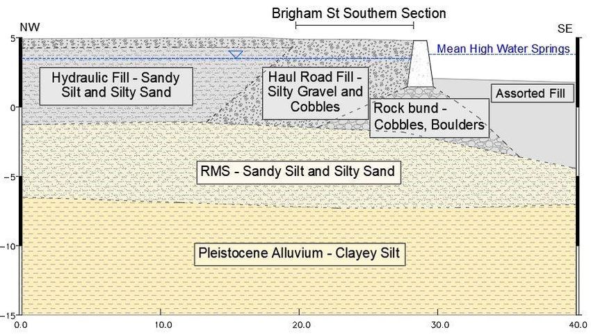
Sensitivity: General
undertaken in two discrete sections, the Southern section of Brigham Street and the Northern section of
Brigham Street, Figure 1.
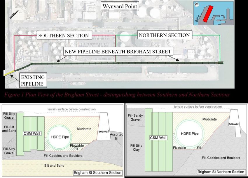
CSM as the selected ground stabilisation technique was carried out along the western boundary of Brigham
Street, to a maximum depth of approximately 9m below the current road level. The purpose of the stabilization
was to enable a 5m deep excavation of trench with self-supporting near-vertical sides for installation of the
pipe. Once formed, the pipeline was laid in 15m lengths and the trench was then backfilled (refer Figure 2).
Figure 2: Cross-sections - Southern Section and Northern Section of Brigham Street
1.2 Ground Condition
The Wynyard Point reclaimed land which includes the construction site and adjacent area, dates from the 1800s
to the 1930s. The Wynyard reclamation was constructed across an old eroded river valley. The reclamations
are bordered by seawalls and piled reinforced concrete wharves. The topography of the site is flat with ground
levels varying from approximately +5.0 to +5.5m CD. The reclamation was developed by forming:
- A perimeter bund with basalt boulders and cobbles, placed on the seabed and constructed to a level of
around 1.3m CD (to base of the seawall), figure 3.
- A rock faced seawall which was then constructed on top of the perimeter bund, before a haul road was
constructed on the western side of the seawall.
- The haul road was constructed on the western side of the seawall, in the southern section, up to
approximately chainage 265 (refer Figure 3). The exact width is not known, but it is likely it was used
to provide access for hauling rockfill along parts of the reclamation edge prior to filling with dredgings
(hydraulic fill). It is variable in character and typically comprises gravel and cobble sized material
within a sandy silt matrix. The gravel and cobbles include basalt, concrete, bricks and other
construction materials. Fragments of steel and pump housings and steel rebar were encountered in test
pits and during the trench excavation.
2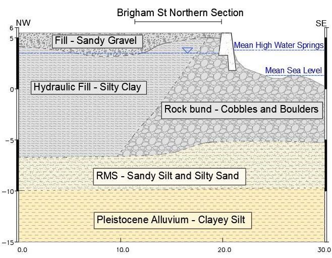
Sensitivity: General

                 -     Hydraulic fill was encountered to the rear of the rock bund and haul road fill. It typically comprises
                       sand, sandy silt, silty sand, silty clay and was encountered mainly within northern section of CSM.
           Groundwater level was at around 3.5mCD in the landside of the seawall and varies from low tide (+0.41mCD)
           to high tide (+3.8mCD) at the other side.
           The published geology of this area indicates that the reclaimed site is underlain by marine sediments then
           Pleistocene alluvium. Recent Marine Sediments (RMS) comprise fine sandy silt and silty sand with some clay
           and trace of shells. The Pleistocene alluvium comprises firm clayey silt and loose to medium dense sand. These
           sit on top of the East Coast Bay Formation alternating sandstone and mudstone (ECBF).

           The area was initially utilised by the timber trade, and then in the 1930’s it started to be used for bulk
           petrochemical storage. Most of the contaminants in the site have originated from activities relating to the
           handling and storage of petroleum hydrocarbons and the historical disposal of gasworks waste during land
           reclamation. Contamination by hydrocarbons has been identified throughout the profile across the site, above
           adopted cleanfill criteria.

           Figure 3: The typical geological profile of southern and northern section

           1.3 Cutter Soil Mixing
           Cutter soil mixing is a type of deep soil mixing method. CSM equipment used on the project consisted of a
           two-wheel Cutter head and a nozzle located between the wheels (See Figure 4). The wheels cut through in-situ
           soil while rotating around their horizontal axes. Simultaneously, cementitious material was pumped through
           the nozzle and mixed with the in-situ soil. Cutter soil mixing improves ground stiffness and strength parameters
           by mixing the in-situ soil with cementitious material. The ease of the process depends on the soil type.
           Soil stabilization was carried out by Wagstaff and comprised four rows of Cutter Soil Mixing (CSM) panels
           installed west of the proposed trench excavation as shown above. The panels were required to extend about
           8.5m below the ground surface unless they encountered the perimeter rock bund and were designed to retain
           reclamation and hydraulic fill to a depth of 5m. The panels were 2.4m long and 1.0m wide, installed parallel
           to the road and excavation. Construction debris and some boulders were removed manually by grabs and
           excavator where the CSM refused at depths higher than the rockbund. Along the southern section, the majority
           of panels terminated at the rockbund at depths 5 to 7m below ground level, however to the north where the fill
           was deeper, the majority of panels reached depths 7-8.5m below ground level. The CSM panels were mostly
           constructed in fill materials and occasionally recent marine sediments.

                                                                     3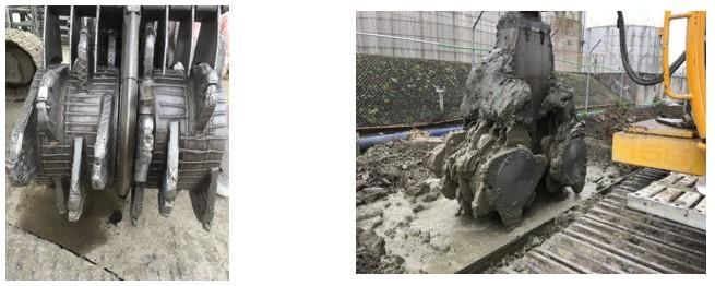
Sensitivity: General

           Figure 4: Cutter Head

           2      QUALITY CONTROL AND ACCEPTANCE CRITERIA
           A quality control program and acceptance criteria were established to confirm the construction met the required
           design criteria. Production trial stabilisation comprising the first 10 panels of each section was established
           whereby more frequent testing was required, and once CSM was confirmed to met design criteria, production
           testing criteria were developed.

           2.1 Sampling Methods and Program
           Sampling methods and programs were divided into two parts: (a) during stabilization of the wet mix and (b)
           after stabilization of the cured mix.

                a. During Stabilizing Sampling of Wet Mix
           During stabilization, wet samples were collected by the Constructor from mixed materials. At each location,
           two samples were taken one at 2 to 3mbgl and one at 5 to 6 mbgl (or within 1m of the panel base) where the
           panels extended that deep. From each wet sample, three test cylinders were made by placing material into a
           mould. The moulds were subsequently sent to the laboratory for Unconfined Compressive Strength (UCS)
           testing. The three cylinders prepared from each wet sample were tested at 7 days, 14 days and 28 days.
           In addition to the wet sampling, double tube sampling was also used to collect test samples using a sampler
           comprising a 6m long inner tube located in a larger outer tube is pushed into the panel, the sample is left to
           harden then the inner tube is removed for curing and UCS testing (see Figure 5).

           .
           Figure 5: Double Tube Sampler

                                                                 4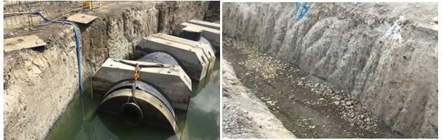
Sensitivity: General

               b. After Stabilizing Sampling of Cured Mix
           Vertical and diagonal cored boreholes were drilled at about 28 days from the date of CSM construction. The
           purpose of the boreholes was to confirm the panel continuity, overlaps, collect samples for UCS testing, and
           confirm mixed depth and founding on rock bund.
           Minimum sample diameter was 85mm and UCS testing was carried out on each sample in accordance with
           NZS4402 Test 6.3.1.

           2.2 Strength Criteria
           The minimum specified UCS was 750 kPa and the minimum specified average UCS was 1MPa. The average
           UCS from core sampling and wet sampling were calculated as the rolling average of the previous 10 results.

           2.3 Uniformity Criteria
           Uniformity of mixing was evaluated based on the core samples. Over any 1.5m section of core sample retrieved
           from the boreholes, the lumps of unimproved soil shall not amount to more than 20 per cent of the total volume
           of the segment and any individual lump or aggregation of lumps of unimproved soil shall be no larger than
           300mm in greatest dimension.

           2.4 Mix Design
           No specific criteria were defined as the acceptable mix design in this project. The constructor designed the mix
           to meet the minimum required strength criteria. The cement content and water-cement ratio were varied during
           construction to meet the strength criteria.

           3      SELECTED TEST RESULTS AND DISCUSSION
           The results are reported in two sections. The first section discusses the unconfined compressive strength of the
           treated soil. The strength of the samples is compared with respect to the Water Cement Ratio (W/C ratio), the
           cement content of the mix, sampling method and age of the sample (7-day, 14-day, and 28-day). The second
           section discusses the uniformity of the constructed panels.

           3.1 Strength
           Figure 6 shows the location of the samples, sampling method, Water/Cement Ratio (W/C ratio), and
           Unconfined Compressive Strength (UCS) of the sample. While W/C ratio of 0.6 to 0.9 applied during mixing,
           UCS fluctuates from ~800kPa to ~15 MPa. Typically, a decrease in UCS is expected by increasing W/C ratio.
           For panels 280 to 490 there is a slight decrease in the average strength compared to panels 66 to 280 where the
           w/c ratio was on average 0.75, however this also coincides with a reduction in cement as shown in Figure 7.
           Figure 7 compares UCS of the samples with the cement content of the soil cement mixture. The cement content
           of 160 kg/m3, 180 kg/m3, 200 kg/m3, and 250 kg/m3 were applied during CSM construction. As above a slight
           reduction in strength is observed in the samples from panels 280 to 490 where less cement was used.
           It is also noted the soils varied between the southern and northern sections, which is also likely to have affected
           the material strength. The northern section (ch 260 to ch 490) comprised finer sandy/silty and clayey materials
           obtaining an average UCS of approximately 2.0MPa. Higher average strengths were obtained in more gravelly
           soils encountered in southern section, (ch066 to ch255), with average strength approximately 4.0MPa.
           Alongside soil type, other variants such as the presence of contaminants including hydrocarbons is another
           factor that may result in inconsistent strength results.

                                                                   5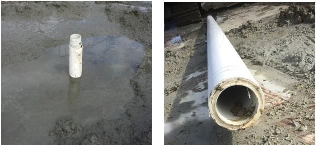
Sensitivity: General

           Figure 6: Unconfined Compressive Strength (UCS) versus Water/Cement Ratio

           Figure 7: Unconfined Compressive Strength (UCS) versus Cement Content

           Figure 8 shows UCS versus sampling methods. UCS of samples with the same W/C ratio, the same cement
           content, and the different sampling methods show a variation in UCS. The wet grab samples would be expected
           to give a higher strength than core samples, as the wet mix is collected and cured in moulds compared to the
           core that is retrieved from drill holes. It is noted the highest strengths were obtained from the wet mix samples,
           however, strengths were not always greater than the core samples.

                                                                   6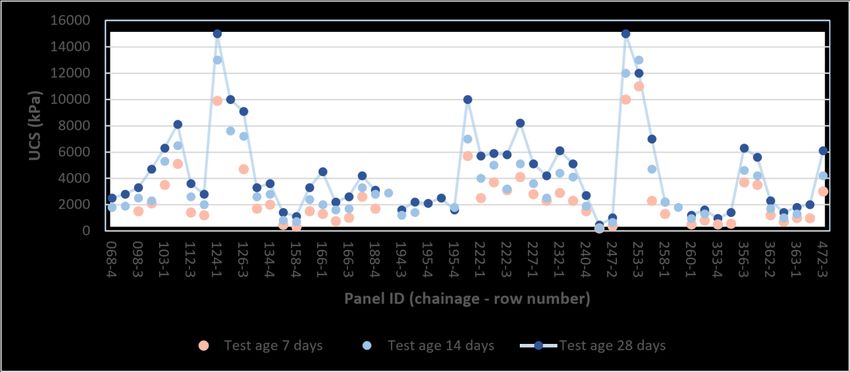
Sensitivity: General

           Figure 8: Sampling Method versus UCS

           Figure 9 depicts wet grab UCS versus age of the sample. In general, the rate of the strength increase was faster
           between day 1 to 14 compared with day 14 to 28 and the mix gained approximately half of its final strength
           within the first 7 days of construction.

           Figure 9: Age versus UCS

           While the observed strengths are highly scattered some conclusions can be made regarding the results. As
           expected, some greater strengths were measured with increased cement content and reduced water content.
           The wet sampling produced the greatest strengths with several over 14 MPa, however, they were not always
           greater than the core results. The high variability of the in-situ soils and presence of contamination would also
           affect the resulting soil strengths.
           The testing did, however, show that the greatest strength gain occurs over the first 7 days from mixing. Testing
           at 7 days provides a good indication of potential strengths at 28 days, as the strength gain from 7 to 28 days
           was relatively consistent.

                                                                  7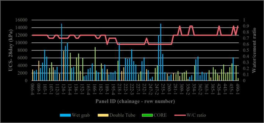
Sensitivity: General

           3.2 Uniformity
           Another important factor of high-quality ground
           improvement is the uniformity of the treated area. In this
           case, it was important that the strength was reliable and
           that each of the panels was overlapped and fully
           connected on all faces with adjacent panels. The photos
           in Figure 10 and 11 represent uniformity of the CSM.
           Despite the variability of the in-situ soil, the excavation
           of the CSM shows a relatively uniform product.

                                                                                  Figure 10: Part of a recovered core

            Figure 11: Open face of CSM wall

           4      SUMMARY AND CONCLUSION
           This paper provides the outcomes of quality and performance of CSM to provide stabilization of a trench
           project in Brigham Street, Auckland, New Zealand. The trench was constructed in reclaimed land. Before
           excavation, the in-situ soil was stabilized by Cutter Soil Mixing. In this method, the in-situ soil is mixed with
           cement and water. A cutter head advances into the in-situ soil and simultaneously mixes the in-situ soil with
           cement and water that is pumped out of a nozzle in the cutter head.
           This paper summarized the strength properties of the treated soil and the uniformity of soil treatment. Due to
           the variability of the in-situ soil (reclaimed area), the strength of the samples was highly scattered, although in
           general, gravelly material of southern section showed higher strengths then sandy/silty and clayey material of
           northern section. Soil contamination above cleanfill criteria is another factor to consider.
           The stabilised soils met the acceptable strength criteria. The majority of the strength gain occurred over the
           first 7 days from mixing which is similar to concrete. Moreover, the surface of the excavation was uniform, it
           was difficult to locate panel joints and no cracks were observed after excavation. It is worth noting that the
           trench remained open for a short period (less than 3weeks).

           5           REFERENCES
           Arnold, M. & Beckhaus, K. & Wiedenmann, U. 2011. Cut-off wall construction using Cutter Soil Mixing: a case study.
           Geotechnik, Nr.1, 34.
           Kermode, L.O. 1992. Geology of the Auckland urban area. Scale 1:50 000. Institute of Geological & Nuclear Sciences
           geological map 2. 1 sheet + 63 p. Institute of Geological & Nuclear Sciences Ltd. Lower Hutt, New Zealand.

                                                                    8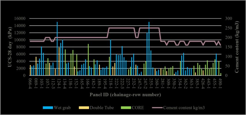

You can also read