Void Free Fuel Solidification in a Foam Shell FIERX Target - Plasma and Fusion Research,ISSN 1880-6821
←
→
Page content transcription
If your browser does not render page correctly, please read the page content below
Plasma and Fusion Research: Regular Articles                                                                   Volume 15, 2404006 (2020)

       Void Free Fuel Solidification in a Foam Shell FIERX Target∗)
                    Akifumi IWAMOTO, Takeshi FUJIMURA1) and Takayoshi NORIMATSU1)
               National Institute for Fusion Science, National Institutes of Natural Sciences, Toki 509-5292, Japan
                            1)
                               Institute of Laser Engineering, Osaka University, Suita 565-0871, Japan
                                         (Received 29 November 2019 / Accepted 3 February 2020)

            We study fuel layering for the Fast Ignition Realization EXperiment (FIREX) cryogenic target with a foam
       shell. A void free solid fuel layer within a porous foam material must be formed ideally. We have demonstrated
       the residual void fraction of ∼1% in a foam wedge with temperature controlled solidification. ANSYS simulations
       have shown that the residual void reduction technique will be applicable to the FIREX target. We examined each
       step in the simulated solidification process using a dummy foam shell target. In several attempts, solid fuel
       formation with a reduced void fraction in the foam shell succeeded.

       c 2020 The Japan Society of Plasma Science and Nuclear Fusion Research

       Keywords: fast ignition laser fusion, cryogenic target, foam shell, void free solid fuel layering
       DOI: 10.1585/pfr.15.2404006

1. Introduction
     FIREX targets have been developed under the collab-
oration research between the Institute of Laser Engineering
(ILE), Osaka University and the National Institute for Fu-
sion Science (NIFS), the National Institutes of Natural Sci-
ences (NINS). The targets are a unique design with a cone
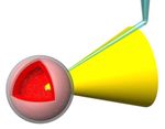
guide for the ignition laser. One of the targets is shown
in Fig. 1. The shell is hollow with a ∼20 µm foam layer.
The porous foam material is impregnated with a void free
solid fuel. This form shell method has been proposed for
Inertial Confinement Fusion (ICF) by direct drive central
ignition [1]. Foam shells have been developed for laser
fusion experiments [2–4].                                                      Fig. 1 Typical appearance of FIREX foam shell target. A cone
     To date, the beta layering technique [5] realizes solid                          guide and a fill tube are attached to a foam shell. The
DT targets for the National Ignition Facility (NIF) and                               shell diameter is 500 µm. A uniform solid fuel has to be
OMEGA for central ignition experiments. The spherical                                 formed within the foam layer of a ∼20 µm thickness. The
                                                                                      sphericity is required to be more than 99%.
symmetry temperature profile makes the solid layer uni-
form. However, the layering technique is not applicable for
the FIREX target with axial symmetry just as they are. The
                                                                               tion process is experimentally demonstrated.
cone becomes a heat exchanger, and therefore, the temper-
ature profile in the shell is naturally not spherical but axial
symmetry. Thus, uniform solid fuel layer formation is a                        2. Foam Shell Method – Residual Void
key technology. The foam shell method which utilizes the                          Reduction in a Foam Shell
capillarity of a porous foam material would have the po-                            Foam is a porous material consisting of ∼100 nm cells.
tential to create a uniform solid fuel layer in axisymmetric                   A liquid fuel is soaked up in the foam uniformly by cap-
targets.                                                                       illary action and then is solidified. Spherical symmetry is
     We study the layering technique on a foam shell tar-                      not required to make a solid layer uniform, and therefore,
get [6], which has an essential challenge. Residual voids                      it would be possible to apply the foam shell method to the
in a formed solid fuel within the porous foam must be re-                      FIREX target without spherical symmetry. However, be-
duced by less than 1%. We have studied the reduction tech-                     cause of the density difference between the liquid and solid
nique of residual voids within ∼1% in principle, and AN-                       phases on H2 , D2 and DT, voids with a fraction of more
SYS simulation has shown its applicability to the FIREX                        than 10% would be developed in the formed solid under
foam shell target [7]. A remaining issue is that the simula-                   random solidifications without any countermeasures.
                                                                                    A residual void reduction procedure has been already
author’s e-mail: iwamoto.akifumi@nifs.ac.jp
∗) This article is based on the presentation at the 28th International Toki    demonstrated using H2 as a surrogate fuel as shown in
Conference on Plasma and Fusion Research (ITC28).                              Fig. 2 [7]. The temperature controlled solidification essen-
                                                                        2404006-1
                                                                                                          c 2020 The Japan Society of Plasma
                                                                                                            Science and Nuclear Fusion Research
Plasma and Fusion Research: Regular Articles Volume 15, 2404006 (2020)
Fig. 2 Solidification process established using a foam wedge.
The temperature gradient between the top and the bottom
makes the solidification front systematic. Solidification
was started from the bottom, and then its front moved up- Fig. 4 Prototype RF foam target with a parylene cone.
ward [7].
the solidification of the whole LH2 . We have succeeded in
reproducing the experimental condition to demonstrate the
residual void reduction using the foam wedge in the foam
shell FIREX target model. This simulation is tested using
a ∼500 µm prototype foam shell target.
3. Prototype RF Foam Target
A 521 µm Resorcinol-Formaldehyde (RF) foam shell
with a parylene cone was prepared as shown in Fig. 4. The
foam shell was produced at ILE. The diameter of the RF
foam shell was 521 µm. The foam layer thickness was
18 µm, and its density was ∼90 mg/cm3 . Parylene was
coated on the shell with a 5.3 µm thickness, and it works as
not only a gas barrier but also as an adhesive to attach the
cone and the shell to each other. The thickness of the cone
was 20 µm. A fill tube of an 8 µm diameter was inserted
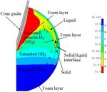
Fig. 3 Successful simulation of solidification control in the into the shell. After no leak was detected at room temper-
500 µm FIREX target [7]. The figure represents tempera-
ature, the target was installed in a NIFS apparatus [8].
ture distribution in the foam shell 8800 sec after the start
of the calculation. The solid/liquid interface is moving
upward in the foam layer. 4. Experiments
The system to examine the condition of the simula-
tion is shown in Fig. 5. The target was set in the ther-
tially creates void free solid within the foam wedge. The mal shield which was cooled by a 4 K Gifford-McMahon
residual void fraction was confirmed to reach to ∼1%. We (GM) cryocooler (RDK-415D, Sumitomo Heavy Indus-
have established the technique to reduce residual voids in tries, Ltd.) with temperature control. The shield also
principle. Then we speculate regarding its applicability to worked as a heat exchanger to control ambient GHe tem-
the FIREX target using ANSYS simulation as shown in perature for the target cooling. The details of the cooling
Fig. 3 [7]. The simulation starts from the condition that system are described in reference 8. Two laser systems, a
the foam layer is filled with liquid H2 (LH2 ). The target 594.1 nm He-Ne laser with 2 mW (HYP020, Tholabs Inc.)
is cooled by the ambient gaseous He (GHe) at the tem- and a 632.8 nm He-Ne laser (05-LHP-151, Melles Griot
perature of 14.0 K, and the cone temperature rises by an Inc.) were prepared for cone heating and for a Michelson
induced heat input of ∼10 µW. As the cone is heated, the interferometer, respectively. Neutral Density (ND) filters
ambient GHe temperature is lowered to 10 K. Solidifica- were applied to control laser energies. A CCD camera with
tion starts from the shell bottom, and then, the solid/liquid a macro lens (DS-5 M with AF Micro-Nikkor 200 mm,
interface is moving upward in the foam layer. The interface Nikon) was used as a microscope. It was possible to ob-
must be the same condition which occurred in the foam serve the target with several µm resolution.
wedge experiment. It takes more than 2300 sec to complete The process in the simulation was not fully repro-
2404006-2Plasma and Fusion Research: Regular Articles Volume 15, 2404006 (2020)
Fig. 6 Observation of LH2 meniscus. (a) vacant shell. (b) visi-
ble meniscus around the cone. (c) LH2 was added from
(b). The meniscus stays in an eccentric position because
the cone was not inserted into the shell at a correct angle.
quence were made to maintain a clear fringe pattern after
solidification. By comparison, solidification without laser
heating was conducted.
Fig. 5 System for solidification control with laser heating. A
microscope and a Michelson interferometer were used to 5. Results
observe liquefaction and solidification in the foam shell. Figure 6 represents the meniscus around the cone
compared to the shell without LH2 . The meniscus of LH2
could be observed by the microscope. We could control
the quantity of LH2 by the meniscus position. The visible
duced because of the limitation of temperature control.
meniscus made it possible for us to fully fill the foam layer
The experimental procedure is as follows. The thermal
with LH2 .
shield temperature was set at 13.5 K, where the shell in-
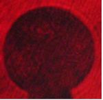
Figure 7 represents four interference patterns. These
side stayed at liquid temperature because heat transfer and
are (a) the shell itself, (b) solidification without laser irra-
thermal conduction of the ambient GHe cause a temper-
diation, (c) solidification in success, and (d) solidification
ature gap. Then gaseous H2 (GH2 ), as a surrogate fuel,
in failure. Fringes clearly appeared through the shell itself
was filled in the shell at the pressure of ∼8 kPa. Lique-
as shown in Fig. 7 (a). Solidification without laser heat-
faction follows. LH2 was soaked in the foam layer. The
ing makes fringes disappear as represented in Fig. 7 (b).
development of liquefaction was confirmed by concentric
The liquid-solid transition might start at random, and the
fringe pattern formation following deformation with the
residual void spaces should be developed within solid H2
interferometer. The liquid quantity was controlled by the
(SH2 ) formed in cells of the foam material. The photo-
GH2 supply pressure. We could maintain the liquid quan-
graph of Fig. 7 (c) was quickly taken without the ND filter
tity overfilling the foam layer by the state of the meniscus
because the fringes were obscure in reduced laser illumi-
around the cone. The 594.1 nm He-Ne laser was irradiated
nation. Controlled solidification with laser heating resulted
to the cone as a heat source to make the cone temperature
in concentric fringe patterns. Experiments successfully re-
higher than other parts of the target. Its power was adjusted
produced the simulation in several attempts. In the case
through an ND400 filter. The absorbed power on the cone
of failure in solidification with laser heating, fringes could
was estimated to be ∼20 µW. This value is comparable to
not be observed as represented in Fig. 7 (d).
that of the simulation. We confirmed that LH2 remained in
the foam layer after the cone heating. Then the shield tem-
perature was lowered step-by-step at an interval of several 6. Summary
mK. Eventually, solidification was observed by a gradually The independent foam shell method has been devel-
altered fringe pattern. Several attempts of the layering se- oped for the FIREX target. Cone temperature control is a
2404006-3Plasma and Fusion Research: Regular Articles Volume 15, 2404006 (2020)
key technology. The solidification process to reduce resid-
ual voids was examined according to the ANSYS simula-
tion. LH2 within the foam layer can be solidified in order,
as we expected. Experiments successfully reproduced the
simulation in several attempts.
Acknowledgments
We would like to thank Y. Fujimoto, Y. Kaneyasu, S.
Machi, H. Hosokawa, M. Nagata, H. Kadota and Y. Suzuki
from ILE, Osaka University for supplying targets.
[1] R.A. Sacks and D.H. Darling, Nucl. Fusion 27, 447 (1987).
[2] M. Takagi et al., J. Vac. Sci. Technol. A 11, 2837 (1993).
[3] A. Nikroo et al., Fusion Sci. Technol. 45, 84 (2004).
[4] K. Nagai et al., Nucl. Fusion 49, 095028 (2009).
[5] J.K. Hoffer and L.R. Foreman, Phys. Rev. Lett. 60, 1310
(1988).
[6] A. Iwamoto et al., Fusion Sci. Technol. 51, 753 (2007).
[7] A. Iwamoto et al., Nucl. Fusion 53, 083009 (2013).
Fig. 7 Interference patterns of the foam shell. (a) the shell itself, [8] A. Iwamoto et al., Fusion Eng. Des. 81, 1647 (2006).
(b) solidification without the laser irradiation, and no pat-
tern appeared, (c) concentric fringe patterns are observed
in the case of success, and (d) no pattern appeared in the
case of failure. Images (a) and (c) were taken without the
ND filter.
2404006-4You can also read


