Versatile metal-wire waveguides for broadband terahertz signal processing and multiplexing
←
→
Page content transcription
If your browser does not render page correctly, please read the page content below
ARTICLE
                  https://doi.org/10.1038/s41467-022-27993-7                 OPEN

                  Versatile metal-wire waveguides for broadband
                  terahertz signal processing and multiplexing
                  Junliang Dong 1 ✉, Alessandro Tomasino1, Giacomo Balistreri1,2, Pei You1, Anton Vorobiov 3,
                  Étienne Charette1, Boris Le Drogoff1, Mohamed Chaker1, Aycan Yurtsever1, Salvatore Stivala2,
                  Maria A. Vincenti4, Costantino De Angelis4, Detlef Kip 3, José Azaña 1 & Roberto Morandotti                                                  1✉
1234567890():,;

                  Waveguides play a pivotal role in the full deployment of terahertz communication systems.
                  Besides signal transporting, innovative terahertz waveguides are required to provide versatile
                  signal-processing functionalities. Despite fundamental components, such as Bragg gratings,
                  have been recently realized, they typically rely on complex hybridization, in turn making it
                  extremely challenging to go beyond the most elementary functions. Here, we propose a
                  universal approach, in which multiscale-structured Bragg gratings can be directly etched on
                  metal-wires. Such an approach, in combination with diverse waveguide designs, allows for the
                  realization of a unique platform with remarkable structural simplicity, yet featuring unpre-
                  cedented signal-processing capabilities. As an example, we introduce a four-wire waveguide
                  geometry, amenable to support the low-loss and low-dispersion propagation of polarization-
                  division multiplexed terahertz signals. Furthermore, by engraving on the wires judiciously
                  designed Bragg gratings based on multiscale structures, it is possible to independently
                  manipulate two polarization-division multiplexed terahertz signals. This platform opens up
                  new exciting perspectives for exploiting the polarization degree of freedom and ultimately
                  boosting the capacity and spectral efficiency of future terahertz networks.

                  1 Institut national de la recherche scientifique, Centre Énergie Matériaux Télécommunications, Varennes, QC J3X 1P7, Canada. 2 Department of Engineering,

                  University of Palermo, Viale delle Scienze, Palermo 90128, Italy. 3 Faculty of Electrical Engineering, Helmut Schmidt University, Holstenhofweg 85, Hamburg
                  22043, Germany. 4 Department of Information Engineering, University of Brescia, Via Branze 38, Brescia 25123, Italy. ✉email: Junliang.Dong@inrs.ca;
                  Roberto.Morandotti@inrs.ca

                  NATURE COMMUNICATIONS | (2022)13:741 | https://doi.org/10.1038/s41467-022-27993-7 | www.nature.com/naturecommunications                                  1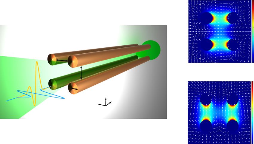
ARTICLE NATURE COMMUNICATIONS | https://doi.org/10.1038/s41467-022-27993-7
D
riven by the global demand for high-data-rate commu- cables for efficient and straightforward connections13. Besides the
nication links, the use of terahertz (THz) radiation1 (with efficient guiding of broadband THz pulses, these waveguides are
frequencies spanning the range between 0.1 and 10 THz) expected to provide a number of options for versatile signal
to carry data-streams will soon become unavoidable2. Despite the processing14,15. However, in contrast to the recent advances in
recent dramatic push towards THz wireless communications3–5, PPWG-based signal-processing devices, such as power splitters16,
THz waveguides serve as an indispensable alternative when a free- multiplexers/demultiplexers17,18, and add-drop filters19, few
space propagation approach is unfeasible6–8. In general, THz signal-processing functionalities have been realized in TWWGs.
waveguides that can preserve both the broad bandwidth and low The underlying reason is that the modal energy is tightly confined
dispersion of a free-space link are desirable. Metal waveguides that in the wavelength-scale space between the two wires10, which
support transverse electromagnetic (TEM) modes, such as limits the possible ways to manipulate the propagating THz waves.
parallel-plate waveguides9 (PPWGs) and two-wire waveguides10 While Bragg gratings, considered among the most fundamental
(TWWGs), are promising candidates due to their capabilities to processing units, have been realized in TWWGs, they typically
support the low-loss and low-dispersion propagation of broad- rely on a hybrid approach that requires inserting standalone
band THz pulses. In particular, compared to the large footprints of metalized papers20,21 or dielectric gratings22 into the waveguides.
PPWGs, TWWGs have several distinct advantages, including This, in turn, severely hampers the realization of more sophisti-
structural simplicity11, tolerance to bending12, and affinity to cated devices and complex processing functionalities.
a c
d
w 1
g
p
Frequency (THz)
0.8
X
Z subwavelength-scale
0.6
T No grooves
1
Subwavelength grooves
0
0.4 Multiscale grooves
wavelength-scale Bragg bandgap
0.2
b
0.1 0.2 0.3 0.4 0.5 0.6 0.7 0.8 0.9 1
d Propagation constant (π/p)
w
g
p T d 8
0.2
6
X (mm)
X 0 4
2
Z multiscale -0.2
0
2.5 3 3.5 4 4.5 5 5.5
Z (mm)
g 5
e
0.2 3
0
X (mm)
2
0
-5 1
Transmission (dB)
-0.2
0
2.5 3 3.5 4 4.5 5 5.5
-10 Z (mm)
-15 Simulation f 0.2 8
X (mm)
6
0 4
-20 Experiment
2
300 μm -0.2
0
-25 2.5 3 3.5 4 4.5 5 5.5
Z (mm)
0.3 0.4 0.5 0.6 0.7 0.8 0.9
Frequency (THz)
Fig. 1 Direct engraving of Bragg gratings on metal-wires. Based on a two-wire waveguide (TWWG) geometry (with a wire radius r = 127 µm and an air
gap g = 300 µm), Bragg gratings are realized by directly engraving grooves with multiscale structures (150-periods-long) along the metal-wires. a
Schematic of the TWWG with sub-λ periodic grooves. Geometry of the grooves: width w = 35 µm, depth d = 40 µm, and period p = 80 µm. b Schematic of
the TWWG with multiscale grooves. This structure is achieved by superimposing a wavelength-scale periodic modulation with period T = 280 µm onto the
sub-λ periodic grooves shown in (a). c Simulated dispersion relations for the plain TWWG (no grooves) and the TWWGs with sub-λ and multiscale
grooves. d Simulated electric field modulus distributions, evaluated at 1.2 THz, in the TWWG with sub-λ grooves, showing that the THz energy is mainly
trapped within the grooves, preventing further propagation. Simulated electric field modulus distributions in the TWWG with multiscale grooves evaluated
at 0.53 THz (e) and at 1.0 THz (f), respectively. g Simulated and experimental transmission spectra of the TWWG with the integrated Bragg gratings. The
experimental result is obtained via a standard THz time-domain spectroscopy (TDS) system. The transmission spectra are achieved by calculating the ratio
between the power spectra of the signals propagating through the TWWGs with and without grooves. The inset shows the optical microscopic image of
the Bragg gratings directly etched on one of the two wires.
2 NATURE COMMUNICATIONS | (2022)13:741 | https://doi.org/10.1038/s41467-022-27993-7 | www.nature.com/naturecommunications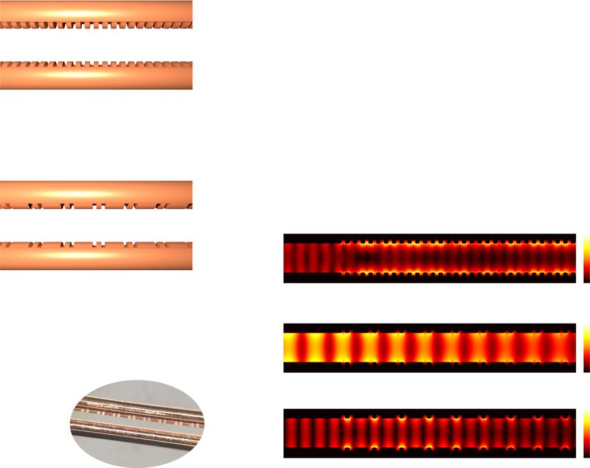
NATURE COMMUNICATIONS | https://doi.org/10.1038/s41467-022-27993-7                                                                       ARTICLE

                                                                                                                b                                    1

                                                                                                                 0.4

                                                                                                            Y (mm)
    a
                                                                                                                     0

                                                                                                                -0.4
                                          g
                                                                                                                                                     0
                                                                                                                         -0.4     0        0.4
                                                                                                                                X (mm)
                                                      g
                                                                                                               c                                     1

                                                r                                                               0.4
                                                                 Y
                                                                      Z
                                                            X

                                                                                                            Y (mm)
                                                                                                                     0

                                                                                                               -0.4

                                                                                                                                                     0
                                                                                                                         -0.4     0        0.4
                                                                                                                                X (mm)

Fig. 2 Geometry and fundamental TEM modes of the four-wire waveguide (FWWG). a Schematic of the FWWG architecture. The FWWG consists of
four identical copper wires (radius r = 127 µm) equally separated by an air gap (g = 300 µm), arranged into a square geometry. b, c Simulated electric field
intensity distributions of the fundamental TEM modes evaluated at 0.5 THz, TEMx (b), and TEMy (c), which can be efficiently excited by x-polarized and y-
polarized THz beams, respectively. The arrows in the 2D distributions indicate the local electric field polarization directions.

   Here, we introduce a universal approach for the realization of               array of grooves in a TWWG. The dispersion relation of such a
broadband THz signal processing in metal-wire waveguides by                     structure (Fig. 1c) is not linear and the group velocity vg of the
engineering the wire surfaces, in turn leading to the realization of            spoof SPPs decreases as the frequency increases. In addition, a cut-
Bragg gratings directly on the metal-wires without the need of                  off frequency fc occurs at ~1.2 THz, indicating that the spoof SPPs
introducing additional materials. This is because the THz gui-                  at such a frequency are inhibited25 and the frequencies above fc
dance in metal-wire waveguides is based on the propagation of                   cannot be guided (Fig. 1d). The propagation characteristics (i.e., vg
THz surface plasmon polaritons (SPPs) along the metal-air                       and fc) of the spoof SPPs can be tailored by engineering the depth
interface, which is extremely sensitive to the metal surface con-               of the grooves d and the duty cycle w/p25 (see Supplementary
ditions. Such an approach can be incorporated into innovative                   Note 1). When the geometry of the grooves is adjusted to the
waveguide designs, further allowing for the realization of more                 wavelength scale, fc will accordingly shift to a lower frequency
complex signal-processing functionalities. As a proof-of-concept,               range, in turn narrowing the operating bandwidth of the wave-
we propose a versatile metal-wire waveguide topology, namely a                  guide. In addition, from a practical viewpoint, fabricating trenches
four-wire waveguide (FWWG), which is capable of sustaining two                  with a wavelength-scale geometry on metal-wires is simply not
independent and orthogonally polarized fundamental modes,                       feasible, since it would greatly lower the robustness of the wires,
thus acting as a broadband polarization-division multiplexer. By                thus potentially leading to their fracture when tension is applied.
integrating Bragg gratings on metal-wires into such a component,                More importantly, by engraving grooves with a single periodicity
we demonstrate the independent manipulation of polarization-                    on the metal-wires, it is impossible to achieve a Bragg resonance
division multiplexed THz signals. The proposed device enables                   spanning the operating THz bandwidth.
polarization-division multiplexing in waveguides with remarkable                   To overcome this issue, while maintaining the operating
structural simplicity, while featuring unprecedented capabilities               bandwidth and the wire robustness, we introduce in the THz
towards processing multiplexed signals over a broad THz                         domain the concept of multiscale structures (Fig. 1b), realized by
frequency range.                                                                superimposing a wavelength-scale periodic modulation of
                                                                                T = 280 µm onto the sub-λ periodic grooves (see Supplementary
                                                                                Note 1). The dispersion relation of the multiscale grooves (Fig. 1c)
Results                                                                         indicates the existence of a Bragg bandgap at 0.53 THz, given by
Directly engraving of multiscale-structured Bragg gratings on                   fBragg = c/(2T)26, where c is the speed of light. The THz electric
metal-wires. When a periodic array of grooves is engraved on the                field distributions also confirm the occurrence of a notch
metal surface, surface states behaving like SPPs, so-called spoof               frequency at 0.53 THz (Fig. 1e), consistent with the Bragg
SPPs, can be supported23. Depending on the spatial period, a                    condition, and the local trapping of the THz energy at 1.0 THz
subwavelength-scale (sub-λ) periodic structure can be treated as                (Fig. 1f). We fabricate a TWWG with integrated Bragg gratings
an effective medium, while a wavelength-scale periodic structure                (see Methods) by directly engraving the multiscale grooves along
behaves as a Bragg grating24. Figure 1a shows a sub-λ periodic                  one of the two wires. As shown in Fig. 1g, the experimental

NATURE COMMUNICATIONS | (2022)13:741 | https://doi.org/10.1038/s41467-022-27993-7 | www.nature.com/naturecommunications                                  3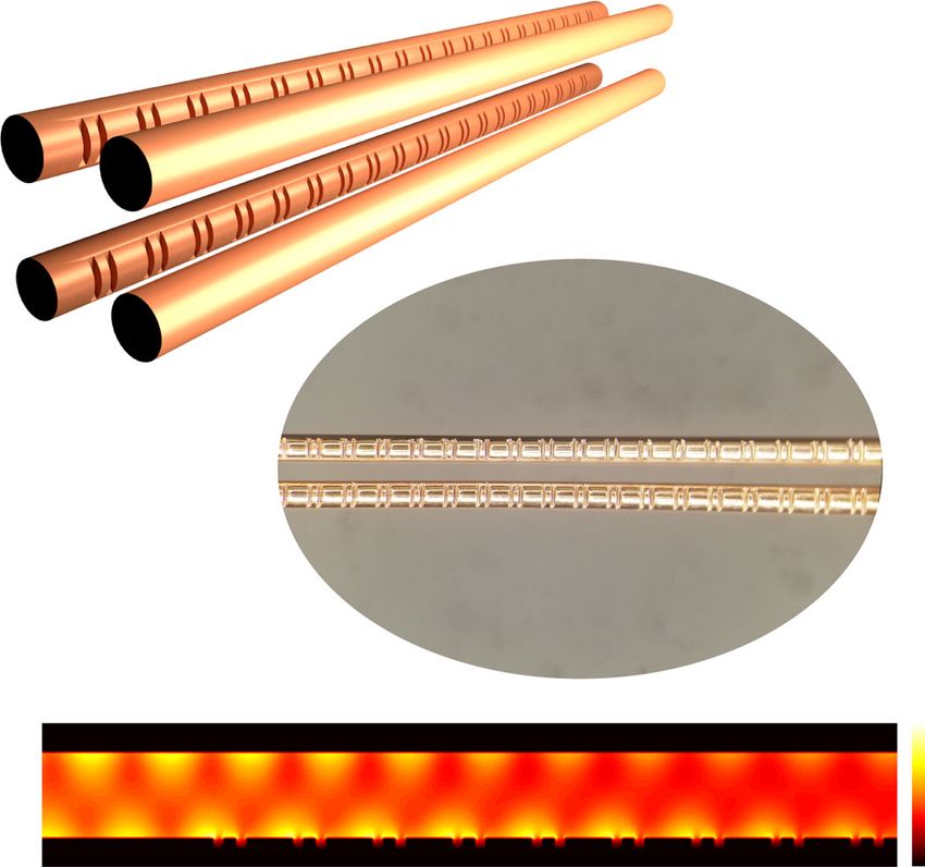
ARTICLE NATURE COMMUNICATIONS | https://doi.org/10.1038/s41467-022-27993-7
Rx
WP L1
M3
M6 Probe beam BS1
PM M2
ZnTe Pump beam
M5
BS2
Tx2
PCA2
Delay line M4
WGP2 SW
TPX2
Multiplexing Tx1
M1
M7
TPX3 WGP1 PCA1
Waveguide
TPX4 TPX1
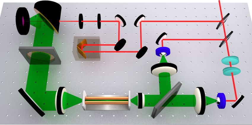
Fig. 3 Schematic of the experimental setup. For the demonstration of polarization-division multiplexing within the FWWG, two independent broadband
transmitters (Tx1 and Tx2) and a single receiver (Rx) are employed. Two identical photoconductive antennas (PCAs) serve as transmitters, emitting a x-
polarized THz beam in Tx1 and a y-polarized THz beam in Tx2. Two THz pulses are first multiplexed in free-space via a wire-grid polarizer (WGP1), while
mutual temporal coherence at the FWWG input is controlled by interposing two silica wedges (SWs) in the Tx1 arm. The orientation of WGP1 is set to 0°,
resulting in the maximum transmission for Tx1 and maximum reflection for Tx2. The multiplexed THz pulses are then focused and coupled onto the 10 cm-
long FWWG. After propagating through the waveguide, the two multiplexed THz pulses are guided towards the detection stage. Demultiplexing and
detection are implemented by using another wire-grid polarizer (WGP2) and a standard electro-optic sampling technique in a ZnTe crystal, respectively.
When the orientation of the WGP2 is set to 0°, the ZnTe crystal axis is rotated in such a way that only the x-polarized signal is recorded (configuration
Rx1); by changing the WGP2 to the 90° position, and rotating the ZnTe crystal axis accordingly, only the y-polarized signal can be reconstructed
(configuration Rx2) (TPX: THz TPX lens; BS: beam splitter; M: mirror; WP: quarter-wave plate; PM: parabolic mirror).
transmission spectrum exhibits a Bragg resonance at ~0.53 THz couple and transmit broadband THz pulses with arbitrary linear
with a notch depth of ~25 dB, which matches the simulated polarization directions in a low-loss and low-dispersion manner. It
transmission spectrum quite well. The achieved linewidth of such is worth mentioning that, in contrast to all the other existing THz
a Bragg resonance (with a Q-factor of ~479.5) is remarkably waveguides27, this is a unique characteristic of the FWWG.
narrow, due to the application of a large number of periods (150 In particular, based on its two fundamental TEM modes, the
periods). By varying the wavelength-scale modulation T, the FWWG is able to support the independent propagation of two
location of the Bragg resonance can be easily tuned over a broad THz pulses multiplexed along the two different polarization axes.
frequency range within 1 THz. For the experimental demonstration, we employ a customized
THz time-domain spectroscopy (TDS) system (Fig. 3) with two
Polarization-division multiplexing of THz pulses within transmitters (Tx1 and Tx2, generating the x- and y-polarized
FWWGs. Building on the concept of TWWG, we introduce the beams, respectively) and a single receiver (configured as Rx1 or
FWWG platform, which features excellent capabilities in terms of Rx2 depending on the selected polarization direction). We
signal transporting (see Supplementary Note 2). The FWWG compare the signals detected via Rx1 and Rx2, under different
consists of four identical copper wires (radius r = 127 µm) equally ON/OFF configurations of Tx1 and Tx2, as shown in Fig. 4.
separated by an air gap (g = 300 µm), arranged into a square When Tx1 is ON and Tx2 is OFF, the signal from Tx1 is detected
geometry, as depicted in Fig. 2a. Its two fundamental modes, via Rx1 and exhibits a single-cycle shape, indicating that the
TEMx (Fig. 2b) and TEMy (Fig. 2c), exhibit symmetric field pro- propagation in the FWWG is nearly dispersion-less; when Tx1 is
files, which are equally divided into two identical portions along OFF but Tx2 is ON, no significant signal from Tx2 is detected via
the axes. Notably, each portion of the field distribution is mainly Rx1, and the corresponding spectra demonstrate an extinction
confined in-between the two corresponding wires and shows a ratio exceeding 20 dB. Concerning the scheme adopted for
similar profile to that of the TWWG, thus indicating that the polarization-division multiplexing, when both Tx1 and Tx2 are
FWWG can also be efficiently accessed by a linearly polarized THz ON, the overall signal retrieved via Rx1 and its spectrum is almost
beam. Specifically, TEMx is excited within the FWWG by an x- identical to those observed when only Tx1 is ON, indicating a
polarized THz beam, while TEMy is excited by a y-polarized THz negligible contribution from Tx2. When the receiver is switched
beam. Remarkably, the FWWG is capable of guiding linearly- to Rx2, the results obtained under various ON/OFF configura-
polarized THz signals with arbitrary polarization directions. This tions exhibit a behavior consistent with the Rx1 configuration
is because an arbitrary linearly-polarized THz beam coupled into (see Fig. 4c, d). Our observations demonstrate that the FWWG
the FWWG is decomposed into the two orthogonal polarization can provide the low-loss, almost dispersion-free, and independent
states, which then propagate independently in terms of its fun- propagation of two broadband THz pulses with orthogonal
damental TEM modes. Experimental results detailed in Supple- polarization states, and as such, it can be operated as a broadband
mentary Note 2 extensively prove the ability of the FWWG to polarization-division multiplexer.
4 NATURE COMMUNICATIONS | (2022)13:741 | https://doi.org/10.1038/s41467-022-27993-7 | www.nature.com/naturecommunicationsNATURE COMMUNICATIONS | https://doi.org/10.1038/s41467-022-27993-7 ARTICLE
a c
THz Amplitude (arb. units) 5 Rx1 5 Rx2
THz Amplitude (arb. units)
Tx1, ON; Tx2, OFF Tx1, ON; Tx2, OFF
4 4
3 3
Tx1, OFF; Tx2, ON Tx1, OFF; Tx2, ON
2 2
1 1
Tx1, ON; Tx2, ON Tx1, ON; Tx2, ON
0 0
-1 -1
40 45 50 55 60 65 70 40 45 50 55 60 65 70
Optical Delay (ps) Optical Delay (ps)
b d
25 Rx1 Tx1, ON; Tx2, OFF 25 Rx2 Tx1, ON; Tx2, OFF
Tx1, OFF; Tx2, ON Tx1, OFF; Tx2, ON
20 20
Power Spectrum (dB)
Power Spectrum (dB)
Tx1, ON; Tx2, ON Tx1, ON; Tx2, ON
15 15
10 10
5 5
0 0
-5 -5
-10 -10
-15 -15
0.4 0.6 0.8 1 1.2 1.4 1.6 1.8 2 0.4 0.6 0.8 1 1.2 1.4 1.6 1.8 2
Frequency (THz) Frequency (THz)
Fig. 4 Experimental demonstration of the independent propagation of two polarization-division multiplexed broadband THz pulses within the four-
wire waveguide (FWWG). Time-domain signals (a) and corresponding spectra (b) reconstructed via Rx1 under different ON/OFF configurations of Tx1
and Tx2. Time-domain signals (c) and corresponding spectra (d) reconstructed via Rx2 under different ON/OFF configurations of Tx1 and Tx2. The THz
time-domain waveforms in (a) and (c) are vertically shifted for clarity.
Independent manipulation of polarization-division multi- a notch depth exceeding 20 dB as expected. We note that limited
plexed THz pulses. Finally, we integrate the Bragg gratings on by the fabrication precision of periodic grooves, the Bragg
metal-wires into the FWWG, in turn allowing us to realize the resonance frequencies realized on the two different wires may not
independent manipulation of two polarization-division multi- exhibit exactly the same value. In addition, due to the imperfect
plexed broadband THz pulses. We fabricate a FWWG with inte- control over the tension manually applied onto the wires, a slight,
grated Bragg gratings by engraving the designed multiscale yet unequal stretch of the periods affects both the sub-λ and
grooves along the two wires on one side of the FWWG (see wavelength-scale structures hosted on different wires. As a result,
Fig. 5a). The transmission spectra of the FWWG with Bragg the overlap of two slightly shifted Bragg resonances leads to the
gratings engraved on different wires are investigated in Supple- formation of a seemingly single resonance with a wider linewidth.
mentary Note 3. Since the grooves are cut along the y-direction (in This fact may explain why the Q-factor of the observed Bragg
turn making them face along the x-direction) and they are rela- resonance (which is ~105.2) is smaller than what we predict in
tively shallow (only 40 µm in depth), they mainly interact with the our simulations. Moreover, a non-Bragg bandgap occurs at
x-polarized THz beam and barely influence the y-polarized THz 0.59 THz in the simulated transmission spectrum. In fact, the
beam in the FWWG (see Supplementary Note 5). As a result, this origin of this non-Bragg bandgap is attributed to a half-
device should ideally feature a notch filter at 0.53 THz for the x- wavelength delay28 between the THz electric fields propagating
polarized THz beam, while behaving as an all-pass filter for the y- along the asymmetric structure. Figure 5e reveals that the electric
polarized THz beam. We perform the experimental characteriza- field propagating on the side containing the grooves is out of
tion using the system in Fig. 3 when both Tx1 and Tx2 are ON. As phase with respect to the field propagating on the unetched side.
shown in Fig. 5c, compared to the reference (i.e., no grooves), the Both location and notch depth of the non-Bragg bandgap are
signal received via Rx1 is attenuated in amplitude and delayed in affected by the shifts between the grooves on the two wires, where
time. In particular, a long-lasting ringing signal is observed cor- the notch depth reaches a maximum when the grooves are
responding to the strong Bragg resonance in the frequency perfectly aligned (see Supplementary Note 4). In the experiments,
domain. In contrast, the signal detected via Rx2 displays the same due to the uneven tightening of the wires, the shifts between the
pulse shape, yet with a slightly lower peak than that of the grooves on different wires are non-consistent, as observed in
reference, demonstrating the practically negligible influence of the Fig. 4b. This explains why we cannot identify the non-Bragg
grooves on the y-polarized THz beam. bandgap, but rather observe an additional ~6 dB loss across the
We investigate the transmission spectra of this device, as range from 0.6 to 0.9 THz. Nevertheless, these shifts have no
shown in Fig. 5d. For Rx1, the experimental transmission impact on the Bragg resonance (see Supplementary Note 4), and
spectrum clearly exhibits a Bragg resonance at ~0.53 THz with thus do not influence the designed filtering function. For Rx2, the
NATURE COMMUNICATIONS | (2022)13:741 | https://doi.org/10.1038/s41467-022-27993-7 | www.nature.com/naturecommunications 5ARTICLE NATURE COMMUNICATIONS | https://doi.org/10.1038/s41467-022-27993-7
c
4
THz Amplitude (arb. units)
Y
a 2
0
X
Z -2
Reference
-4
Rx2
-6 Rx1
b
-8
35 40 45 50 55 60 65
Optical Delay (ps)
d 5
0
Power Ratio (dB)
-5
500 μm Y
-10
Rx2: Simulation
Z
-15 Rx2: Experiment
e Rx1: Simulation
0.2 3 -20
Rx1: Experiment
X (mm)
0.1 2
0 -25 Bragg bandgap
-0.1 1 Non-Bragg bandgap
-0.2 -30
0
2.5 3 3.5 4 4.5 5 5.5 0.3 0.4 0.5 0.6 0.7 0.8 0.9
Z (mm) Frequency (THz)
Fig. 5 Independent manipulation of polarization-division multiplexed broadband THz pulses within the four-wire waveguide (FWWG). a Schematic of
the FWWG with Bragg gratings (150-periods-long) engraved along two of the four wires (top and bottom left wires), both placed on the same side of the
FWWG. In this case, the multiscale grooves mainly interact with the x-polarized THz beam and barely influence the y-polarized THz beam. b Optical
microscopic image of the multiscale grooves engraved along the two wires of the FWWG. c Experimental characterization of the FWWG hosting the
integrated Bragg gratings, performed by using two broadband THz pulses multiplexed in polarization. The THz signals detected via Rx1 and Rx2 are
recorded and plotted together with the reference signal obtained from an unetched FWWG (i.e., no gratings on the wires). d Comparison between the
simulated and experimental transmission spectra of the FWWG containing the integrated Bragg gratings. e Simulated distributions of the electric field
modulus evaluated at 0.59 THz, for a x-polarized THz beam (cross-sectional view at y = r + g/2).
experimental transmission spectrum exhibits an all-pass response Methods
as predicted in our simulations, except for a slight loss (NATURE COMMUNICATIONS | https://doi.org/10.1038/s41467-022-27993-7 ARTICLE
5 kHz and with a peak-to-peak amplitude of 12 V, was generated by a low-noise 16. Reichel, K. S., Mendis, R. & Mittleman, D. M. A broadband terahertz
function generator and applied to the PCAs. A THz TPX lens (BATOP) with a waveguide T-junction variable power splitter. Sci. Rep. 6, 28925 (2016).
diameter of 25.4 mm and a focal length of 10 mm was used to focus the THz pulses 17. Karl, N. J., McKinney, R. W., Monnai, Y., Mendis, R. & Mittleman, D. M.
into the waveguide. Such a lens allowed us to focus the THz beam down to a waist Frequency-division multiplexing in the terahertz range using a leaky-wave
diameter of 400 µm at 0.5 THz. The THz pulses were detected by carrying out the antenna. Nat. Photonics 9, 717–720 (2015).
electro-optic sampling technique in a 3 mm-thick ZnTe crystal. The use of 18. Ma, J., Karl, N. J., Bretin, S., Ducournau, G. & Mittleman, D. M. Frequency-
such a thick crystal allowed us to achieve a larger temporal window in the mea- division multiplexer and demultiplexer for terahertz wireless links. Nat.
surements, which was necessary to acquire the long-lasting THz transient as Commun. 8, 729 (2017).
modulated by the multiscale grooves. Each recorded THz waveform was centered 19. Reichel, K. S. et al. Electrically reconfigurable terahertz signal processing
in a time window of 100 ps with a time resolution of 0.05 ps. devices using liquid metal components. Nat. Commun. 9, 4202 (2018).
20. Yan, G. et al. Low-loss terahertz waveguide Bragg grating using a two-wire
Fabrications. The fabrication process of the grooves on the bare copper wires was waveguide and a paper grating. Opt. Lett. 38, 3089 (2013).
performed at the LMN laboratory at the INRS-EMT, Canada. First, the wires were 21. Cao, Y., Nallappan, K., Guerboukha, H., Xu, G. & Skorobogatiy, M. Additive
kept as straight and flat as possible and were glued on a quartz plate. Then the manufacturing of highly reconfigurable plasmonic circuits for terahertz
quartz plate with the wires was installed on the base of an automatic dicing saw. communications. Optica 7, 1112 (2020).
The thickness of the employed diamond blade was 35 µm, which determines 22. Mridha, M. K. et al. Active terahertz two-wire waveguides. Opt. Express 22,
the width of the grooves. The grooves along the wires were fabricated by utilizing 22340 (2014).
the three-dimensional motor control of the dicing saw. Deviations in the depth 23. Maier, S. A., Andrews, S. R., Martín-Moreno, L. & García-Vidal, F. J.
were mainly induced by the blade wearing over several cuts. The width of the Terahertz surface plasmon-polariton propagation and focusing on periodically
grooves was constant with the exception of a few burrs at the edge of the cuts. corrugated metal wires. Phys. Rev. Lett. 97, 1–4 (2006).
To mount the wires22, two PMMA slabs with holes were used to hold and support 24. Meng, Y. et al. Topological interface states in multiscale spoof-insulator-spoof
them. The diameter of the holes was set to 1037 µm in order to guarantee that the waveguides. Opt. Lett. 41, 3698 (2016).
gap size between wires was 300 µm in each direction. Screws on the slabs were 25. Gan, Q., Fu, Z., Ding, Y. J. & Bartoli, F. J. Ultrawide-bandwidth slow-light
used to apply tension to the wires, so as to maintain a uniform gap all along system based on THz plasmonic graded metallic grating structures. Phys. Rev.
the waveguide. Lett. 100, 256803 (2008).
26. Lee, E. S. et al. Terahertz band gaps induced by metal grooves inside parallel-
Data availability plate waveguides. Opt. Express 20, 6116 (2012).
All experimental raw data that support the findings of this study are provided in the 27. Atakaramians, S., Afshar, V. S., Monro, T. M. & Abbott, D. Terahertz
Source Data file. All the other relevant data are available from the corresponding authors dielectric waveguides. Adv. Opt. Photonics 5, 169 (2013).
upon reasonable request. Source data are provided with this paper. 28. Lee, E. S., Ji, Y. B. & Jeon, T. I. Terahertz band gap properties by using metal
slits in tapered parallel-plate waveguides. Appl. Phys. Lett. 97, 95–98 (2010).
29. Pereira, M. F., Anfertev, V., Shevchenko, Y. & Vaks, V. Giant controllable
Code availability gigahertz to terahertz nonlinearities in superlattices. Sci. Rep. 10, 15950
Any simulation and computational codes for this study are available from the (2020).
corresponding authors upon reasonable request. 30. Balistreri, G. et al. Time‐domain integration of broadband terahertz pulses in a
tapered two‐wire waveguide. Laser Photon. Rev. 15, 2100051 (2021).
31. Calvanese Strinati, E. et al. 6G: The next frontier: From holographic messaging
Received: 13 June 2021; Accepted: 15 December 2021;
to artificial intelligence using subterahertz and visible light communication.
IEEE Veh. Technol. Mag. 14, 42–50 (2019).
32. Saad, W., Bennis, M. & Chen, M. A vision of 6G wireless systems:
Applications, trends, technologies, and open research problems. IEEE Netw.
34, 134–142 (2020).
33. Lee, Y.-S. Principles of Terahertz Science and Technology (Springer US, 2009).
References
1. Nagatsuma, T., Ducournau, G. & Renaud, C. C. Advances in terahertz
communications accelerated by photonics. Nat. Photonics 10, 371–379 (2016). Acknowledgements
2. Dang, S., Amin, O., Shihada, B. & Alouini, M. What should 6G be? Nat. This work was supported by the Natural Sciences and Engineering Research Council of
Electron. 3, 20–29 (2020). Canada (NSERC) through the Discovery and Strategic grant programs. J.D. acknowl-
3. Koenig, S. et al. Wireless sub-THz communication system with high data rate. edges financial support from the Mitacs Elevate Postdoctoral Fellowship. R.M. would also
Nat. Photonics 7, 977–981 (2013). like to acknowledge support from the Canada Research Chair Program.
4. Ummethala, S. et al. THz-to-optical conversion in wireless communications
using an ultra-broadband plasmonic modulator. Nat. Photonics 13, 519–524
(2019). Author contributions
5. Harter, T. et al. Wireless THz link with optoelectronic transmitter and J.D. conceived the idea and designed the samples. J.D., A.T., and G.B. performed the
receiver. Optica 6, 1063 (2019). experiments and analyzed the experimental results. J.D. and P.Y. performed the
6. Amarasinghe, Y., Zhang, W., Zhang, R., Mittleman, D. M. & Ma, J. Scattering numerical simulations. É.C., B.L.D, M.C, A.V., and D.K. contributed to the sample
of terahertz waves by snow. J. Infrared, Millimeter, Terahertz Waves 41, fabrication. M.A.V. and C.D.A. helped with the interpretation of the simulation results.
215–224 (2020). A.Y., S.S., and J.A. contributed to the data analysis. R.M. supervised and coordinated the
7. Ma, J. et al. Security and eavesdropping in terahertz wireless links. Nature 563, project. All authors wrote and revised the manuscript.
89–93 (2018).
8. Yang, Y. et al. Terahertz topological photonics for on-chip communication. Competing interests
Nat. Photonics 14, 446–451 (2020). The authors declare no competing interests.
9. Mendis, R. & Grischkowsky, D. Undistorted guided-wave propagation of
subpicosecond terahertz pulses. Opt. Lett. 26, 846 (2001).
10. Pahlevaninezhad, H., Darcie, T. E. & Heshmat, B. Two-wire waveguide for Additional information
terahertz. Opt. Express 18, 7415 (2010). Supplementary information The online version contains supplementary material
11. Wang, K. & Mittleman, D. M. Metal wires for terahertz wave guiding. Nature available at https://doi.org/10.1038/s41467-022-27993-7.
432, 376–379 (2004).
12. Mbonye, M., Mendis, R. & Mittleman, D. M. A terahertz two-wire waveguide Correspondence and requests for materials should be addressed to Junliang Dong or
with low bending loss. Appl. Phys. Lett. 95, 1–4 (2009). Roberto Morandotti.
13. Shrestha, R. et al. A wire waveguide channel for terabit-per-second links. Appl.
Phys. Lett. 116, 131102 (2020). Peer review information Nature Communications thanks Levi Smith and the
14. Sengupta, K., Nagatsuma, T. & Mittleman, D. M. Terahertz integrated anonymous reviewer(s) for their contribution to the peer review of this work.
electronic and hybrid electronic–photonic systems. Nat. Electron. 1, 622–635
(2018). Reprints and permission information is available at http://www.nature.com/reprints
15. Ma, T., Nallapan, K., Guerboukha, H. & Skorobogatiy, M. Analog signal
Publisher’s note Springer Nature remains neutral with regard to jurisdictional claims in
processing in the terahertz communication links using waveguide Bragg
published maps and institutional affiliations.
gratings: Example of dispersion compensation. Opt. Express 25, 11009 (2017).
NATURE COMMUNICATIONS | (2022)13:741 | https://doi.org/10.1038/s41467-022-27993-7 | www.nature.com/naturecommunications 7ARTICLE NATURE COMMUNICATIONS | https://doi.org/10.1038/s41467-022-27993-7
Open Access This article is licensed under a Creative Commons
Attribution 4.0 International License, which permits use, sharing,
adaptation, distribution and reproduction in any medium or format, as long as you give
appropriate credit to the original author(s) and the source, provide a link to the Creative
Commons license, and indicate if changes were made. The images or other third party
material in this article are included in the article’s Creative Commons license, unless
indicated otherwise in a credit line to the material. If material is not included in the
article’s Creative Commons license and your intended use is not permitted by statutory
regulation or exceeds the permitted use, you will need to obtain permission directly from
the copyright holder. To view a copy of this license, visit http://creativecommons.org/
licenses/by/4.0/.
© The Author(s) 2022
8 NATURE COMMUNICATIONS | (2022)13:741 | https://doi.org/10.1038/s41467-022-27993-7 | www.nature.com/naturecommunicationsYou can also read


