VDL200 - Vector inverter for lifts with asynchronous motors - Gefran
←
→
Page content transcription
If your browser does not render page correctly, please read the page content below
Vector inverter for lifts with

                                           SIEIDrive
    asynchronous motors

                                 VDL200
                           .... Quick start up guide
                      Specification and installation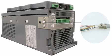
Information about this manual

                      The VDL200 Quick start guide is a handy-sized manual for mechanical installation, electrical connection and fast
                      start-up.
                      The manual explaining the functions and a description of the parameters can be found on the CD provided with the
                      drive.

                      Software version
                      This manual is updated according the software versions V1.X.0..

                      The identification number of the software version is indicated on the identification plate of the drive or can be checked
                      with the Firmware ver.rel - PAR 490 parameter, menu 2.6.

                      General information

    Note ! 		In industry, the terms “Inverter”, “Regulator” and “Drive” are sometimes interchanged. In this document, the term “Drive” will be used.

                      Before using the product, read the safety instruction section carefully. Keep the manual in a safe place and available to
                      engineering and installation personnel during the product functioning period.
                      Gefran S.p.A has the right to modify products, data and dimensions without notice. The data can only be used for the
                      product description and they can not be understood as legally stated properties.

                      Thank you for choosing this Gefran product.
                      We will be glad to receive any possible information which could help us improvingthis manual. The e-mail address is
                      the following: techdoc@gefran.com.
                      All rights reserved

2                                                     VDL200 • Quick installation guide - Specifications and connection
Table of Contents
Information about this manual........................................................................................................ 2
1 - Safety Precautions...................................................................................................................... 5
1.1 Symbols used in the manual................................................................................................................................................ 5
1.2 Safety precaution.................................................................................................................................................................. 5
1.3 General warnings................................................................................................................................................................. 6
1.4 Disclaimer............................................................................................................................................................................. 6
2 - Introduction to the product......................................................................................................... 7
2.1 Dedicated features............................................................................................................................................................... 7
2.2 Other features....................................................................................................................................................................... 8
2.3 Identification of components................................................................................................................................................. 9
2.4 Product identification.......................................................................................................................................................... 10
3 - Transport and storage............................................................................................................... 11
3.1 General............................................................................................................................................................................... 11
3.2 Permissible Environmental Conditions............................................................................................................................... 11
4 - Specification.............................................................................................................................. 12
4.1 Environmental Conditions................................................................................................................................................... 12
4.2 Standards........................................................................................................................................................................... 12
4.3 Precision............................................................................................................................................................................. 12
4.3.1 Speed control......................................................................................................................................................................................12
4.3.2 Speed control limits.............................................................................................................................................................................12
4.3.3 Torque control......................................................................................................................................................................................12
4.3.4 Current rating......................................................................................................................................................................................12
4.4 Input electrical data ........................................................................................................................................................... 13
4.5 Output electrical data ......................................................................................................................................................... 13
4.5.1 Derating values in overload condition.................................................................................................................................................13
4.5.2 Derating values for switching frequency.............................................................................................................................................14
4.5.3 Kalt: Ambient temperature reduction factor.........................................................................................................................................14
4.6 Voltage level of the inverter for safe operations ...................................................................................................................... 14
4.7 No-load consumption (Energy rating)....................................................................................................................................... 14
4.8 Cooling............................................................................................................................................................................... 15
4.9 Weights and dimensions.................................................................................................................................................... 16
5 - Options....................................................................................................................................... 18
5.1 Optional external fuses ...................................................................................................................................................... 18
5.1.1 Network side fuses (F1)......................................................................................................................................................................18
5.2 Input chokes....................................................................................................................................................................... 18
5.2.1 AC input chokes..................................................................................................................................................................................18
5.2.2 DC input chokes..................................................................................................................................................................................18
5.3 AC output chokes............................................................................................................................................................... 19
5.4 External braking resistors (optional)................................................................................................................................... 19
5.5 EMC Filter (optional)........................................................................................................................................................... 20
6 - Mechanical installation............................................................................................................. 21
6.1 Maximum inclination and assembly clearances................................................................................................................. 21
6.2 Fastening positions ............................................................................................................................................................ 22
7 - Wiring Procedure....................................................................................................................... 23
7.1 Power section..................................................................................................................................................................... 24
7.1.1 Cable cross-sections...........................................................................................................................................................................24
7.1.2 Connection of shielding (recommended)............................................................................................................................................25
7.1.3 EMC guide line....................................................................................................................................................................................25
7.1.4 Block diagram of power section..........................................................................................................................................................26
7.1.5 Internal EMC filter (standard)..............................................................................................................................................................26
7.1.6 Power line connection ........................................................................................................................................................................26
7.1.7 Connection of AC and DC chokes (optional).......................................................................................................................................26
7.1.8 Motor connection.................................................................................................................................................................................27
7.1.9 Connection of braking resistor (optional)............................................................................................................................................27
7.2 Regulation section.............................................................................................................................................................. 28
7.2.1 Cable cross-sections...........................................................................................................................................................................28
7.2.2 Connection of I/O................................................................................................................................................................................28
7.2.3 Feedback Connection.........................................................................................................................................................................29
7.3 Connection diagrams.......................................................................................................................................................... 31
7.3.1 Regulation potentials, digital I/O.........................................................................................................................................................31
7.3.2 Typical connection diagram.................................................................................................................................................................31
7.3.3 Emergency connection diagram..........................................................................................................................................................32
VDL200 • Quick installation guide - Specifications and connection 37.4 Serial interface (PC connector).......................................................................................................................................... 33
7.4.1 Drive/RS232 port point-to-point connection........................................................................................................................................33
7.5 Optional Keypad interface (keypad connector).................................................................................................................. 34
7.6 Braking............................................................................................................................................................................... 35
7.6.1 Braking unit (internal)..........................................................................................................................................................................35
8. Use of the keypad....................................................................................................................... 36
8.1 Description of KB-ADL optional programming keypad....................................................................................................... 36
8.1.1 Membrane keypad...............................................................................................................................................................................36
8.1.2 Meaning of LEDs.................................................................................................................................................................................36
8.2 Navigating with the optional keypad................................................................................................................................... 37
8.2.1 Scanning of the first and second level menus ....................................................................................................................................37
8.2.2 Display of a parameter .......................................................................................................................................................................37
8.2.3 Scanning of the parameters ...............................................................................................................................................................38
8.2.4 List of the last parameters modified ...................................................................................................................................................38
8.2.5 "FIND" function....................................................................................................................................................................................38
8.2.6 Parameter modification ......................................................................................................................................................................38
8.2.7 How to save parameters ....................................................................................................................................................................39
8.2.8 Configuration of the display.................................................................................................................................................................40
8.2.8.1 Language selection ...................................................................................................................................................................................................40
8.2.8.2 Selection of Easy/Expert mode..................................................................................................................................................................................40
8.2.9 Startup display.....................................................................................................................................................................................40
8.2.10 Back-lighting of the display...............................................................................................................................................................40
8.2.11 Alarms................................................................................................................................................................................................40
8.2.11.1 Alarm reset................................................................................................................................................................................................................40
8.2.12 Messages..........................................................................................................................................................................................41
8.2.13 Saving and recovery of new parameter settings ..............................................................................................................................41
8.2.13.1 Selection of the keypad memory .............................................................................................................................................................................41
8.2.13.2 Saving of parameters on the keypad .......................................................................................................................................................................41
8.2.13.3 Load parameters from keypad .................................................................................................................................................................................42
9 - Commissioning via keypad ..................................................................................................... 43
9.1 Asynchronous motor startup wizard (with the optional keypad)......................................................................................... 45
10 - Troubleshooting................................................................................................................................................................. 52
10.1 Alarms............................................................................................................................................................................... 52
10.2 Speed fbk loss alarm according to the type of feedback.................................................................................................. 55
10.2.1 Reset Speed fbk loss alarm..............................................................................................................................................................55
10.2.2 Encoder error alarm..........................................................................................................................................................................55
10.3 Messages......................................................................................................................................................................... 56
Appendix.......................................................................................................................................... 59
A.1 - I/O Specification............................................................................................................................................................... 59
A.1.1 Input/Output features..........................................................................................................................................................................59
A.2 Encoders and Phasing....................................................................................................................................................... 61
A.2.1 Encoders.............................................................................................................................................................................................61
A.2.2 Phasing...............................................................................................................................................................................................62
A.3 - Brake monitoring system (A3 Amendment)..................................................................................................................... 63
A.3.1 Introduction.........................................................................................................................................................................................63
A.3.2 Configuration of the brake fault alarm.................................................................................................................................................64
A.3.3 Maintenance of the brake fault alarm function....................................................................................................................................64
A.3.4 Troubleshooting..................................................................................................................................................................................64
4 VDL200 • Quick installation guide - Specifications and connection1 - Safety Precautions
1.1 Symbols used in the manual
Indicates a procedure, condition, or statement that, if not strictly observed, could result in personal injury or death.
Indique le mode d’utilisation, la procédure et la condition d’exploitation. Si ces consignes ne sont passtrictement
Warning!
respectées, il y a des risques de blessures corporelles ou de mort.
Indicates a procedure, condition, or statement that, if not strictly observed, could result in damage to or destruction
of equipment.
Caution Indique le mode d’utilisation, la procédure et la condition d’exploitation. Si ces consignes ne sont pas strictement
respectées, il y a des risques de détérioration ou de destruction des appareils.
Indicates that the presence of electrostatic discharge could damage the appliance. When handling the boards, always
wear a grounded bracelet.
Indique que la présence de décharges électrostatiques est susceptible d’endommager l’appareil. Toujours porter un
bracelet de mise à la terre lors de la manipulation des cartes.
Indicates a procedure, condition, or statement that should be strictly followed in order to optimize these applications.
Indique le mode d’utilisation, la procédure et la condition d’exploitation. Ces consignes doivent êtrerigoureusement respectées
Attention pour optimiser ces applications.
Note ! Indicates an essential or important procedure, condition, or statement.
Indique un mode d’utilisation, de procédure et de condition d’exploitation essentiels ou importants
Qualified personnel
For the purpose of this Instruction Manual, a “Qualified person” is someone who is skilled to the installation, mounting,
start-up and operation of the equipment and the hazards involved. This operator must have the following qualifications:
- trained in rendering first aid.
- trained in the proper care and use of protective equipment in accordance with established safety procedures.
- trained and authorized to energize, de-energize, clear, ground and tag circuits and equipment in accordance with
established safety procedures.
Personne qualifiée
Aux fins de ce manuel d’instructions, le terme « personne qualifiée » désigne toute personne compétente en matière
d’installation, de montage, de mise en service et de fonctionnement de l’appareil et au fait des dangers qui s’y
rattachent. L’opérateur en question doit posséder les qualifications suivantes :
- formation lui permettant de dispenser les premiers soins
- formation liée à l’entretien et à l’utilisation des équipements de protection selon les consigne de sécurité en vigueur
- formation et habilitation aux manoeuvres suivantes : branchement, débranchement, vérification des isolations, mise
à la terre et étiquetage des circuits et des appareils selon les consignes de sécurité en vigueur
Use for intended purpose only
The power drive system (electrical drive + application plant) may be used only for the application stated in the manual
and only together with devices and components recommended and authorized by Gefran.
Utiliser uniquement dans les conditions prévues
Le système d’actionnement électrique (drive électrique + installation) ne peut être utilisé que dans les conditions
d’exploitation et les lieux prévus dans le manuel et uniquement avec les dispositifs et les composants recommandés et
autorisés par Gefran.
1.2 Safety precaution
The following instructions are provided for your safety and as a means of preventing damage to the product or compo-
nents in the machines connected. This section lists instructions, which apply generally when handling electrical drives.
Specific instructions that apply to particular actions are listed at the beginning of each chapters.
Les instructions suivantes sont fournies pour la sécurité de l’utilisateur tout comme pour éviter l’endommagement
du produit ou des composants à l’intérieur des machines raccordées. Ce paragraphe dresse la liste des instructions
généralement applicables lors de la manipulation des drives électriques.
Les instructions spécifiques ayant trait à des actions particulières sont répertoriées au début de chaque chapitre.
Read the information carefully, since it is provided for your personal safety and will also help prolong the service life of
VDL200 • Quick installation guide - Specifications and connection 5your electrical drive and the plant you connect to it.
Lire attentivement les informations en matière de sécurité personnelle et visant par ailleurs à prolonger la durée de vie
utile du drive tout comme de l’installation à laquelle il est relié.
1.3 General warnings
This equipment contains dangerous voltages and controls potentially dangerous rotating mechanical parts. Non-
compliance with Warnings or failure to follow the instructions contained in this manual can result in loss of life,
severe personal injury or serious damage to property.
Cet appareil utilise des tensions dangereuses et contrôle des organes mécaniques en mouvement potentiellement
dangereux. L’absence de mise en pratique des consignes ou le non-respect des instructions contenues dans ce
manuel peuvent provoquer le décès, des lésions corporelles graves ou de sérieux dégâts aux équipements.
Only suitable qualified personnel should work on this equipment, and only after becoming familiar with all safety
notices, installation, operation and maintenance procedures contained in this manual. The successful and safe
operation of this equipment is dependent upon its proper handling,installation, operation and maintenance.
Seul un personnel dûment formé peut intervenir sur cet appareil et uniquement après avoir assimilé l’ensemble des
informations concernant la sécurité, les procédures d’installation, le fonctionnement et l’entretien contenues dans
ce manuel. La sécurité et l’efficacité du fonctionnement de cet appareil dépendent du bon accomplissement des
opérations de manutention, d’installation, de fonctionnement et d’entretien.
In the case of faults, the drive, even if disabled, may cause accidental movements if it has not been disconnected
from the mains supply.
En cas de panne et même désactivé, le drive peut provoquer des mouvements fortuits s’il n’a pas été débranché de
l’alimentation secteur.
Electrical Shock
The DC link capacitors remain charged at a hazardous voltage even after cutting off the power supply.
Never open the device or covers while the AC Input power supply is switched on. Minimum time to wait before
working on the terminals or inside the device is listed in section 4.6.
Risque de décharge électrique
Les condensateurs de la liaison à courant continu restent chargés à une tension dangereuse même après que la
tension d’alimentation a été coupée.
Ne jamais ouvrir l’appareil lorsqu’il est suns tension. Le temps minimum d’attente avant de pouvoir travailler sur les
bornes ou bien àl’intérieur de l’appareil est indiqué dans la section 4.6.
Electrical Shock and Burn Hazard:
When using instruments such as oscilloscopes to work on live equipment, the oscilloscope’s chassis should be
grounded and a differential probe input should be used. Care should be used in the selection of probes and leads
and in the adjustment of the oscilloscope so that accurate readings may be made. See instrument manufacturer’s
instruction book for proper operation and adjustments to the instrument.
Décharge Èlectrique et Risque de Brúlure : Lors de l’utilisation d’instruments (par example oscilloscope) sur des
systémes en marche, le chassis de l’oscilloscope doit être relié à la terre et une sonde différentiel devrait être utilisé
en entrée. Les sondes et conducteurs doivent être choissis avec soin pour effectuer les meilleures mesures à l’aide
d’un oscilloscope. Voir le manuel d’instruction pour une utilisation correcte des instruments.
Fire and Explosion Hazard:
Fires or explosions might result from mounting Drives in hazardous areas such as locations where flammable or
combustible vapors or dusts are present. Drives should be installed away from hazardous areas, even if used with
motors suitable for use in these locations.
Risque d’incendies et d’explosions: L’utilisation des drives dans des zônes à risques (présence de vapeurs ou de
poussières inflammables), peut provoquer des incendies ou des explosions. Les drives doivent être installés loin des
zônes dangeureuses, et équipés de moteurs appropriés.
1.4 Disclaimer
Any remote connection functions shall be used only under adequate security conditions, in compliance with current
regulatory provisions and only by properly trained personnel. The evaluation of such conditions is up to the user.
6 VDL200 • Quick installation guide - Specifications and connection2 - Introduction to the product
The SIEIDrive VDL200 is the result of GEFRAN’s experience in the civil lift engineering sector, gained from its
commitment to working in close partnership with leading operators in the sector to develop technical solutions and
application programs.
The VDL200 integrates the most complete and advanced lift inverter technology, to offer a cost-effective and immediate
solution for lift control systems.
This drive is designed to power loads such as asynchronous motors, for applications in the lift sector.
This compact drive is suitable for installation in cabinets for roomless applications.
Designed and produced to meet the full range of requirements in the lift sector.
• Management of asynchronous motors
• 8 programmable digital inputs (NPN/PNP) + an Enable input
• 4 single-contact programmable relay outputs
• Input for 5 Vdc TTL incremental digital encoder
• 1 analog input
• Speed regulator with monitoring of the correct lifting or dropping of the machine brake according to 5.6.7 of EN
81-20:2014 and 5.8 of EN 81-50:2014 (respectively 9.11.3 and F.8 of EN 81-1:1998 + A3:2009)
• Integrated EMI filter (models VDL200-...-F)
• Suitable for UPS emergency operation
• Optimized sensorless control.
2.1 Dedicated features
The VDL200 incorporates basic and advanced lift functions in a single product, to ensure maximum comfort for all
systems at all times.
• Speed control
EFC (Elevator Floor Control) function: separate function for independent management of short floors, landing zone,
re-starting with lift not at floor and automatic deceleration point calculation.
• Lift sequence
Typical sequence of input/output signals used in civil lift engineering applications such as I/O management, braking,
output contactor and door control.
• Parameters in linear unit
Possibility of selecting different engineering units (also with values for the US) for the main movement parameters, rpm
(fpm) or m/s for speed, m/s², m/s³ (ft/s2, ft/s3) for cabin acceleration.
• Lift mechanical parameters
Mechanical system parameters such as pulley diameter and speed ratio for converting system units and weights,
system for calculating inertia and speed regulation for the desired response.
• Ramp generation
Independent configuration of acceleration and deceleration ramp parameters and of the 4 jerk values for maximum
travelling comfort in the lift cabin. Two independent S-shaped ramps, selectable via digital input with 4 independent jerk
settings. Dedicated deceleration ramp corresponding to the stop command.
• Multiple speeds
8 internally settable speed reference values. Possibility of overwriting at start-up with additional values to ensure
smooth starting.
• Pre-torque (load compensation)
Initialisation of the speed regulator by the weight sensor to prevent jerks or bumpy starting.
• Increased overload
Overload capacity in line with typical lift application load cycles.
• Fan control logic
The fan control logic activates the internal fans according to the temperature.
• Emergency single-phase power supply to return to the floor
In emergency conditions a 230 V single-phase supply voltage can be used to return the cabin to the floor (by UPS
power supply or batteries with EMS module).
• User-friendly menus
The menus feature lift-specific DISPLAY and motor STARTUP terminology
VDL200 • Quick installation guide - Specifications and connection 7• Saving parameters
Drive parameters can be saved on the keypad (5 settings).
• Integrated encoder management
5 V TTL incremental digital encoder.
2.2 Other features
• Autotuning of motor parameters.
• SSC (Sensorless Scalar Control) modulation reduces noise levels to a minimum.
• Switching frequency fixed at 10 kHz.
• Output voltage up to 98% of input voltage.
• Saving of messages relating to the last 30 repairs and indication of time of repair.
• Drive, motor and braking unit overload protection.
• Speed regulator adaptive.
• Readout of speed functions.
• Easy use of the equipment via:
- terminal strip
- optional keypad, simple and immediate to use, with magnetic fastening and remote control at distances of up to 15 m.
• Drives are fitted with IGBTs (insulated gate bipolar transistors).
• The output is protected against accidental grounding and output phase short circuit
• Speed regulator powered by switched-mode power supply from DC bus.
• Mains dip protection.
• Galvanic isolation between power and regulation sections.
8 VDL200 • Quick installation guide - Specifications and connection2.3 Identification of components
The inverter converts the constant frequency and voltage of an existing three-phase network into DC voltage, from
which it obtains a new three-phase network with variable voltage and frequency. With this variable three-phase network
the speed of three-phase asynchronous motors can be controlled continuously.
3 4 5 7 8
1 2
M
3
6
1. Mains supply voltage
2. Mains choke (see chapter 5.2)
3. Three-phase rectifier bridge
Converts AC voltage into DC voltage via a three-phase full wave bridge.
4. Intermediate circuit
With pre-load resistor and levelling capacitors DC voltage (Udc) =√2 x mains voltage (Uln)
5. IGBT inverter bridge
Converts DC voltage into three-phase AC voltage with variable amplitude and frequency
6. Configurable control section
Cards for controlling and regulating the closed and open-loop power section. Commands, references and reactions
are connected to these.
7. Output voltage
Three-phase AC voltage.
8. Speed feedback encoder (see paragraph "7.2.3 Feedback Connection")
VDL200 • Quick installation guide - Specifications and connection 92.4 Product identification
The basic technical data of the inverter are included in the product code and data plate.
The inverter must be selected according to the rated current of the motor.
The rated output current of the drive must be higher than or equal to the rated current of the motor used.
The speed of the asynchronous motor depends on the number of pole pairs and frequency (plate and catalog data).
If using a motor at speeds above the rated speed, contact the motor manufacturer for any related mechanical problems
(bearings, unbalance, etc.). The same applies in case of continuous operation at frequencies of less than approx. 20 Hz
(inadequate cooling, unless the motor is provided with forced ventilation).
Name of model (code)
VDL 200 1 040 - X B L - F -4
Rated voltage:
4 = 400Vca, three-phase
EMI FILTER:
F = included
Lift application:
L = included
Braking unit:
X = not included
B = included
Keypad:
X = not included
Inverter power in kW:
040 = 4kW 150 = 15kW
055 = 5,5kW 185 = 18.5kW
075 = 7,5kW 220 = 22kW
110 = 11kW
Mechanical dimensions of the drive:
1 = size 1 3 = size 3
2 = size 2
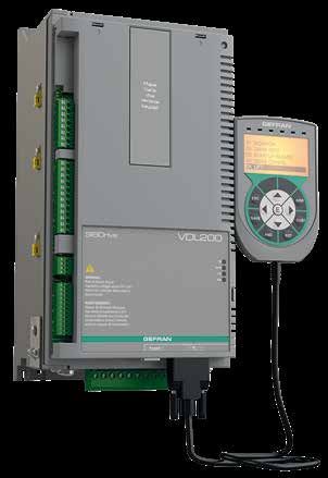
Inverter, VDL200 series
Data plate
Type = Drive model; S/N = Serial number
Inp = Input (mains supply, frequency, AC Input
Current at constant torque)
Out = Output (Output voltage, frequency, power,
current, overload)
Approvals
Firmware and card revision plate
P = Power, R = Regulation
SW . CFG = Software revision
Prod CONF. = Product configuration
Position of plates on the drive
10 VDL200 • Quick installation guide - Specifications and connection3 - Transport and storage
Correct transport, storage, erection and mounting, as well as careful operation and maintenance are essential for
proper and safe operation of the equipment.
Caution Protect the inverter against physical shocks and vibration during transport and storage. Also be sure to protect it
against water (rainfall) and excessive temperatures.
Le bon accomplissement des opérations de transport, de stockage, d’installation et de montage, ainsi que
l’exploitation et l’entretien minutieux, sont essentiels pour garantir à l’appareil un fonctionnement adéquat et sûr.
If the Drives have been stored for longer than two years, the operation of the DC link capacitors may be impaired
and must be “reformed”. Before commissioning devices that have been stored for long periods, connect them to a
power supply for two hours with no load connected in order to regenerate the capacitors, (the input voltage has to be
applied without enabling the drive).
En cas de stockage des variateurs pendant plus de deux ans, il est conseillé de contrôler l’état des condensateurs
CC avant d’en effectuer le branchement. Avant la mise en service des appareils, ayant été stockés pendant long
temps, il faut alimenter variateurs à vide pendant deux heures, pour régénérer les condensateurs : appliquer une
tension d’alimentation sans actionner le variateur.
3.1 General
A high degree of care is taken in packing the VDL200 Drives and preparing them for delivery. They should only be
transported with suitable transport equipment (see weight data). Observe the instructions printed on the packaging.
This also applieswhen the device is unpacked and installed in the control cabinet.
Upon delivery, check the following:
- the packaging for any external damage
- whether the delivery note matches your order.
Open the packaging with suitable tools. Check whether:
- any parts were damaged during transport
- the device type corresponds to your order
In the event of any damage or of an incomplete or incorrect delivery please notify the responsible sales offices
immediately. The devices should only be stored in dry rooms within the specified temperature ranges.
Note! A certain degree of moisture condensation is permissible if this arises from changes in temperature. This does not, however, apply when the devices are in
operation. Always ensure that there is no moisture condensation in devices that are connected to the power supply!
3.2 Permissible Environmental Conditions
Temperature:
storage �������������������������������� -25…+55°C (-13…+131°F), class 1K4 per EN50178
-20…+55°C (-4…+131°F), for devices with keypad
transport ������������������������������� -25…+70°C (-13…+158°F), class 2K3 per EN50178
-20…+60°C (-4…+140°F), for devices with keypad
Air humidity:
storage �������������������������������� 5% to 95 %, 1 g/m3 to 29 g/m3 (Class 1K3 as per EN50178)
transport ������������������������������� 95 % (3), 60 g/m3 (4)
A light condensation of moisture may occur for a short time occasionally if the device is not in operation (class 2K3 as per EN50178)
Air pressure:
storage �������������������������������� [kPa] 86 a 106 (class 1K4 as per EN50178)
transport ������������������������������� [kPa] 70 a 106 (class 2K3 as per EN50178)
(3) Greatest relative air humidity occurs with the temperature @ 40°C (104°F) or if the temperature of the device is brought suddenly from -25 ...+30°C (-13°...+86°F).
(4) Greatest absolute air humidity if the device is brought suddenly from 70...15°C (158°...59°F).
VDL200 • Quick installation guide - Specifications and connection 114 - Specification
4.1 Environmental Conditions
Installation location �������������������� Pollution degree 2 or lower (free from direct sunligth, vibration, dust, corrosive or
inflammable gases, fog, vapour oil and dripped water, avoid saline environment)
Installation altitude �������������������� Max 2000m (6562 feet) above sea level. With 1.2% reduction in output current for every
100 m starting from 1000 m.
Mechanical conditions for installation ����� Vibrational stress: EN 60721-3-3 Class 3M1
Operating temperature ����������������� -10…+45°C (32°…113°F)
Operating temperature ����������������� +45 ... +50°C (+113 … +122°F) with 1% derating every °C starting from 45°C and up to
50°C. Operation at temperatures of > 50°C is not allowed
Air humidity (operating) ����������������� from 5 % to 85 % and from 1 g/m3 to 25 g/m3 with no humidity (or condensation)
Air pressure (operating) [kPa] ������������ from 70 to 106
4.2 Standards
Climatic conditions �������������������� EN 60721-3-3
Electrical safety ����������������������� EN 50178, EN 61800-5-1, UL508C, UL840 degree of pollution 2
Vibration ����������������������������� Class 3M1 EN 60721-3-3
EMC compatibility ��������������������� EN 12015
Protection degree ��������������������� IP20
Approvals ����������������������������
EC directives ������������������������� LVD 2014/35/EU, EMC 2014/30/EU, Lift 2014/33/EU, RoHs 2011/65/EU
4.3 Precision
4.3.1 Speed control
Speed control precision ������������������ Flux vector CL control with feedback and brushless: 0.01 % motor rated speed
Flux vector OL control: ± 30 % rated slip of motor
SSC control: ± 60 % rated slip of motor
4.3.2 Speed control limits
Speed range (*) ������������������������ ± 32000 rpm
Speed format (*) ����������������������� 32 bit
Frequency range ����������������������� ± 2000 Hz
Max frequency ������������������������ Flux vector CL control with feedback and brushless: 300Hz, FVOL: 150 Hz, VF: 600 Hz
Min frequency ������������������������ 0 Hz
(*) referred to Full scale speed, PAR:680.
4.3.3 Torque control
Torque resolution (*) �������������������� > 0.1 %
Torque control precision (*) ��������������� Flux vector CL with feedback: ± 5%
Direct torque control �������������������� yes
Current limitation ����������������������� Limits ±, Mot/gen limits, Variable limits
(*) referred to rated torque
4.3.4 Current rating
Overload ����������������������������� 200% *10 sec with output frequency more than 3 Hz
150% with output frequency less than 3 Hz.
Switching frequency �������������������� 10 kHz
12 VDL200 • Quick installation guide - Specifications and connection4.4 Input electrical data
Choke ������������������������������� Sizes 1...2: Optional (DC or AC).
Note! See chapter 5.2 for THD values in accordance with EN 12015 and for selection of external inductances.
Input
Input Overvoltage Undervoltage DC-Link
voltage Effective input current In (@ In out)
Size frequency threshold threshold Capacity
Uln
(Vdc) (Vdc)
(Vac) (Hz) @ 230 Vac (A) @ 400 Vac (A) (µF)
VDL200-...-4 , 3ph
1040 12 11 470
1055 17 16 680
2075 23 22 680
three-phase @ 230 Vac = 225 Vdc;
50/60 Hz,
2110 230 - 400 Vac 820 Vdc @ 380 Vac = 371 Vdc; 31 29 1020
± 5%
-15%+10% @ 400 Vac = 391 Vdc.
3150 42 40 1500
3185 50 47 2250
3220 55 53 2700
4.5 Output electrical data
Maximum output voltage U2 �������������� 0.98 x Uln (Uln = AC input voltage)
Maximum output frequency f2 ������������� 300 Hz
The derating factors shown in the table below are applied to the rated DC output by the user. They are not automati-
cally implemented by the drive: Idrive = In x Kalt x Kt.
Pn mot
In Rated output current
(Recommended motor power ,fsw Reduction factor
(fsw = default)
= default)
IGBT
Size
@Uln = 230Vac @Uln = 400Vac @Uln = 230Vac @Uln = 400Vac Kt Kalt braking unit
(A) (A) (kW) (kW) (1) (2)
VDL200-...-4, 3ph
1040 9 9 2 4 0.95 1.2
1055 13.5 13.5 3 5.5 0.95 1.2
2075 18.5 18.5 4 7.5 0.95 1.2 Standard internal
(with external
2110 24.5 24.5 5,5 11 0.95 1.2
resistor); braking
3150 32 32 7.5 15 0.95 1.2 torque 150% MAX
3185 39 39 9 18.5 0.95 1.2
3220 45 45 11 22 0.95 1.2
(1) Kt: Derating factor for ambient temperature of 50°C (1% every °C above 45°C)
(2) Kalt: Derating factor for installation at altitudes above 1000 meters a.s.l. Value to be applied = 1.2% each 100 m increase above 1000 m.
E.g.: Altitude 2000 m, Kalt = 1.2% * 10 = 12% derating; In derated = (100 - 12) % = 88 % In
4.5.1 Derating values in overload condition
In overload conditions the output current depends on the output frequency, as shown in the figure below.
Figure 4.5.1-A: Ratio between overload/output frequency
OL (% IN)
200
150
3 F out (Hz)
VDL200 • Quick installation guide - Specifications and connection 134.5.2 Derating values for switching frequency
The switching frequency is modified according to the temperature of the drive (measured on the heat sink), as shown in
the figure below.
Figure 4.5.2: Ratio between switching frequency/heat sink temperature
FSW (kHz)
10
5
T diss th T diss (°C)
4.5.3 Kalt: Ambient temperature reduction factor
Figure 4.5.3: Tamb reduction coefficient
KT
1.00
0.95
Function not allowed
Range of ambient temperatures allowed
-10 45 50 T amb (°C)
4.6 Voltage level of the inverter for safe operations
The minimum time between the moment in which an VDL200 inverter is disabled from the mains and that in which an
operator can operate on internal parts of the inverter, without the danger of electric shock, is 5 minutes.
This value takes into account the time to turn off an inverter supplied without any options (time indicated for disabled inverter condition).
Attention
4.7 No-load consumption (Energy rating)
Size No. of pre-loads allowed Power-on Stand-by consumption Fan consumption Stand-by consumption
time "Fan Off" "Fan On"
[secs] [W] [W] [W]
VDL200-...-4, 3ph
1040 1 each 20 sec. 5 abt. 20 4 24
1055 1 each 20 sec. 5 abt. 20 10 30
2075 1 each 20 sec. 5 abt. 20 10 30
2110 1 each 20 sec. 5 abt. 20 8 28
3150 1 each 20 sec. 5 abt. 20 16 36
3185 1 each 20 sec. 5 abt. 20 15 35
3220 1 each 20 sec. 5 abt. 20 15 35
14 VDL200 • Quick installation guide - Specifications and connection4.8 Cooling
All inverters are equipped with internal fans.
Size Pv Fan capacity Minimum cabinet opening for
(Heat dissipation) cooling
@Uln=230...400Vac (*) Heat sink (m3/h) Internal (m3/h) (cm2)
VDL200-...-4, 3ph
1040 150 35 - 72
1055 250 2 x 58 - 144
2075 350 2 x 58 - 144
2110 400 2 x 35 - 144
3150 600 2 x 98 32 328
3185 700 2 x 98 32 328
3220 900 2 x 10⁴ 32 328
(*) values that refer to operation at default switching frequency.
VDL200 • Quick installation guide - Specifications and connection 154.9 Weights and dimensions
Figure 4.9.1: Size 1 dimensions
115 159
5.5
318.5
321.2
337
343
11
162 8.3
115
148.1
Dimensions: Width x Height x Depth Weight
Sizes
(mm) (inches) (kg) (lbs)
VDL200-1040-...-4
162 x 343 x 159 6.38 x 13.50 x 6,26 5.6 12.3
VDL200-1055-...-4
Figure 4.9.2: Size 2 dimensions
115
5.5 159
373.5
376.2
392
396
8.3
162
11
115
148.1
Dimensions: Width x Height x Depth Weight
Sizes
(mm) (inches) (kg) (lbs)
VDL200-2075-...-4
162 x 396 x 159 6.38 x 15.59 x 6.26 7.6 16.7
VDL200-2110-...-4
16 VDL200 • Quick installation guide - Specifications and connectionFigure 4.9.3: Size 3 dimensions
235
156 168
5.5
9
40 156
374.7
374
392
456.5
306
180
9
164
64.5
218.3
Dimensions: Width x Height x Depth Weight
Sizes
(mm) (inches) (kg) (lbs)
VDL200-3150-...-4
VDL200-3185-...-4 235 x 456.5 x 180 9,25 x 17.97 x 7.08 10.5 23.15
VDL200-3220-...-4
VDL200 • Quick installation guide - Specifications and connection 175 - Options
5.1 Optional external fuses
5.1.1 Network side fuses (F1)
The inverter must be fused upstream on the network side.
Use fast-acting fuses only.
F1 - External network side fuses
DC link capacitor hours of EUROPE AMERICA
Size service life [h] Type Code Type Code
VDL200-...-4, 3ph
1040 > 15000 GRD2/20 F4D15 A70P20 S7G48
1055 > 15000 GRD2/25 F4D16 A70P25 S7G51
2075 > 15000 GRD3/35 F4D20 A70P40 S7G52
2110 > 15000 Z22GR40 F4M16 A70P40 S7G52
3150 > 15000 Z22GR63 F4M17 A70P60-4 S7I34
3185 > 15000 Z22GR80 F4M19 A70P80 S7G54
3220 > 15000 Z22GR80 F4M19 A70P80 S7G54
Technical data for fuses, including dimensions, weights, power leakage, fuse carriers etc. are reported in the corresponding manufacturers' data sheets:
GRD... (E27), S00... Jean Müller, Eltville
A70... Ferraz
5.2 Input chokes
The three-phase mains choke is strongly recommended in order to:
- limit the RMS input current of the VDL200 inverter.
- increase the life of intermediate circuit capacitors and reliability of input diodes.
- reduce mains harmonic content
- reduce problems due to power supply via a low impedance line (≤ 1%).
In accordance with EN 12015 (THD values < 35%), provide the following:
- sizes ≤ 22kW: DC input inductance (see paragraph 5.2.2)
5.2.1 AC input chokes
Effective input current In
(@400V/50Hz, with AC input Dimensions: W x H x d Weight
Size Model Code
chokes) mm [inches] kg [lbs]
(A)
VDL200-...-4, 3ph
1040 9 LR3y-2040 S7AAG 120 x 125 x 65 [4.7 x 4.9 x 2.6] 2 [4.4]
1055 13.5 LR3y-2055 S7AB5 120 x 125 x 75 [4.7 x 4.9 x 2.6] 2.2 [4.4]
2075 18 LR3y-2075 S7AB6 150 x 155 x 79 [5.9 x 6.1 x 3.1] 4.9 [10.8]
2110 24 LR3y-3110 S7AB7 150 x 155 x 79 [5.9 x 6.1 x 3.1] 5 [11]
3150 32 LR3y-3150 S7AB8 150 x 169 x 85 [5.9 x 6.7 x 3.3] 5.5 [12.1]
3185 39 LR3y-3150 S7AB8 150 x 169 x 85 [5.9 x 6.7 x 3.3] 5.5 [12.1]
3220 44.5 LR3-022 S7FF4 180 x 182 x 130 [7.1 x 7.2 x 5.1] 7.8 [17.2]
5.2.2 DC input chokes
Effective input current In
External DC chokes
(with external DC chokes)
Size Rated Overload Dimensions:
@230V/50Hz @400V/50Hz Model Code Weight
current current Width x Height x Depth
(A) (A) (Arms) (*) (Arms) mm [inches] kg [lbs]
1040 8 8 10 20 LDC-004 S7AI10 99 x 96 x 93 [3.90 x 3.78 x 3.66] 2.4 [5.3]
1055 12 12 16 31 LDC-005 S7AI11 125 x 112 x 98 [4.92 x 4.41 x 3.86] 4.1 [9.0]
2075 16 16 21 41 LDC-007 S7AI12 125 x 127 x 122 [4.92 x 5.00 x 4.80] 4.9 [10.8]
2110 21 21 28 54 LDC-011 S7AI13 125 x 127 x 142 [4.92 x 5.00 x 5.59] 6.6 [14.6]
3150 28 28 36 70 LDC-015 S7AI14 125 x 127 x 152 [4.92 x 5.00 x 5.98] 8 [17.6]
3185 34 34 45 90 LDC-022 S7AI15 155 x 160 x 148 [6.10 x 6.30 x 5.83] 8.5 [18.7]
3220 39.5 39.5 45 90 LDC-022 S7AI15 155 x 160 x 148 [6.10 x 6.30 x 5.83] 8.5 [18.7]
18 VDL200 • Quick installation guide - Specifications and connection5.3 AC output chokes
The VDL200 inverter can be used with standard motors or motors designed specifically for use with inverters.
The latter usually have a higher isolation rating to better withstand PWM voltage Examples of reference regulations
are provided below: motors designed for use with inverters do not require any specific filtering of output from the
inverter. For standard motors, especially with long cable runs (typically over 100 m) an output choke may be necessary
to maintain the voltage waveform with the specified limits.
The range of recommended chokes are listed in the following table. The rated current of the chokes should be approx.
20% higher than that of the inverter in order to take into account additional losses due to modulation of the output
waveform.
Dimensions: W x H x d Weight
Size Model Code
mm [inches] kg [lbs]
VDL200-...-4, 3ph
1040 LU3-005 S7FG3 180 x 170 x 110 [7.1 x 6.7 x 4.3] 5.8 [12.8]
1055 LU3-005 S7FG3 180 x 170 x 110 [7.1 x 6.7 x 4.3] 5.8 [12.8]
2075 LU3-005 S7FG3 180 x 170 x 110 [7.1 x 6.7 x 4.3] 5.8 [12.8]
2110 LU3-011 S7FG4 180 x 180 x 130 [7.1 x 7.1 x 5.1] 8 [17.6]
3150 LU3-015 S7FH2 180 x 160 x 170 [7.1 x 6.3 x 6.7] 7.5 [16.5]
3185 LU3-015 S7FH2 180 x 160 x 170 [7.1 x 6.3 x 6.7] 7.5 [16.5]
3220 LU3-022 S7FH3 180 x 160 x 185 [7.1 x 6.3 x 7.3] 8 [17.6]
Note! With the inverter operated at the rated current and a frequency of 50 Hz, the output chokes cause a voltage drop of approx. 2% of the output voltage.
5.4 External braking resistors (optional)
Recommended combinations for use with internal braking unit.
Table 5.4.1: Recommended combination VDL200
Size List and technical data of standard external resistors
Resistor type Code Q.ty Max. overload, 1" Max. overload, Pnbr Rbr Housing Dimensions: Weight
- service 10% 30" - service 25% WxHxd kg
Ebr (kJ) Ebr (kJ) (W) (Ω) mm
VDL200-...-4, 3ph
1040 RFPD 750 DT 100R S8SY4 1 7.5 38 750 100 IP44 200 x 70 x 106 1.7
1055 RFPR 750 D 68R S8SZ3 1 7.5 38 750 68 IP44 245 x 75 x 100 2.7
2075 RFPR 750 D 68R S8SZ3 1 7.5 28 750 68 IP44 245 x 75 x 100 2.7
2110 RFPR 1200 D 49R S8SZ4 1 7.5 28 1200 49 IP44 310 x 75 x 100 4.2
3150 RFPR 1900 D 28R S8SZ5 1 12 43 1500 28 IP44 365 x 75 x 100 4.2
3185 BRT4K0-15R4 S8T00G 1 40 150 4000 15.4 IP20 625 x 100 x 250 7.0
3220 BRT4K0-15R4 S8T00G 1 40 150 4000 15.4 IP20 625 x 100 x 250 7.0
Pnbr Braking resistor rated power
Rbr Braking resistor ohmic value
Ebr Maximum energy that can be dissipated on the resistor
Braking resistors may be subject to unexpected overloads due to faults.
Resistors MUST be protected using thermal cutouts. These devices must not interrupt the circuit in which the resistor is
Warning! inserted but their auxiliary contact must cut off the power supply to the power section of the drive. If the resistor requires a
protection contact, this must be used together with that of the thermal cutout.
A la suite de pannes, les résistances de freinage peuvent être sujettes à des surcharges imprévues. La protection des
résistances au moyen de dispositifs de protection thermique est absolument capitale. Ces dispositifs ne doivent pas inter-
rompre le circuit qui abrite la résistance, mais leur contact auxiliaire doit couper l’alimentation du côté puissance du drive.
Si la résistance prévoit un contact de protection, ce dernier doit être utilisé conjointement à celui du dispositif de protection
thermique.
VDL200 • Quick installation guide - Specifications and connection 19You can also read